2011 IEEE International Conference on Ultra-Wideband (ICUWB)
Performance Analysis of Code-Multiplexed
Transmitted-Reference Ultra-Wideband Systems
Mehmet Emin Tutay�, Sinan Gezici�, and H. Vincent Poort
�
Dept. of Electrical and Electronics Engineering, Bilkent University, Ankara 06800, Turkey t Department of Electrical Engineering, Princeton University, Princeton, NJ 08544, USA{tutay,gezici}@ee.bilkent.edu.tr, [email protected]
Ahstract-In code-multiplexed transmitted-reference (CM TR) ultra-wideband (UWB) systems, data signals and reference signals are transmitted using two distinct orthogonal codes. In this way, performance improvements and/or implementation advantages are obtained compared to transmitted-reference (TR) and frequency-shifted reference (FSR) ultra-wideband (UWB) systems. In this study, performance of CM-TR systems is investi gated, and probability of error expressions are obtained. For the single user case, a closed-form expression for the exact probability of error is derived, whereas a Gaussian approximation, the accu racy of which depends on the number of frames per symbol, is considered for the multiuser case. Also, the maximum likelihood detector is derived, and numerical examples are presented.
Index Terms-Ultra-wide band, impulse radio, multiple-access interference, code-multiplexed transmitted-reference.
I. INTRODUCTION
Due to their large bandwidth and high time resolution, ultra wideband (UWB) signals can be used for high-speed data transmission [1], and accurate range and location estimation [2]. In addition, UWB systems can be used for low-to-medium data rate communication with low cost receivers. In order to implement UWB systems, impulse radio (IR) systems can be employed [3], [4]. In IR systems, a train of pulses with durations on the order of a nanosecond are transmitted. Each pulse resides in an interval called a frame, and a number of frames are employed for each information symbol. The information symbol can be carried by the positions or ampli tudes of pulses. In multiple access environments, in order to prevent collisions and increase robustness against interfering users, pulses of each user are transmitted according to a time hopping (TH) sequence, which aims to decrease the probability of collision between pulses of different users [3]. In addition to a data modulation scheme, each pulse can have a polarity randomization code that provides additional robustness against multiple access interference (MAl) and eliminates spectral lines that violate the UWB spectral mask [5].
In practice, each transmitted UWB pulse reaches a receiver via tens or even hundreds of paths in a multipath environment. Hence, to collect energy from multipath components, Rake receivers can be employed [6]. Due to the large number of fingers [7] and high sampling requirements, implementation of Rake receivers can be challenging for UWB systems. In order to ease the strict requirements of channel estima tion, transmitted-reference (TR) UWB systems [8], [9] and frequency-shifted reference (FSR) UWB systems [10] have been proposed. In these types of systems, one reference pulse and one data pulse are sent in each frame. The reference pulse contains no information and its channel response is used at the receiver, removing the need for channel estimation. Despite this important advantage, TR and FSR UWB systems have
some disadvantages and limitations. In TR systems, to achieve orthogonality between data and reference signals, an analog delay line, which creates miniaturization problems, is needed. In FSR systems the orthogonality is achieved in the frequency domain and the analog delay line requirement is removed, resulting in a significantly simpler receiver. However, this im plementation has data rate limitations [11]. On the other hand, code-orthogonalized transmitted reference (COTR) or code multiplexed transmitted-reference (CM-TR) UWB systems [12], [13], which employ two distinct orthogonal codes for orthogonalization purposes, require a much simpler receiver and have no data rate limitations.
Although CM-TR systems are investigated in [12]-[14] for single-user and multi-user systems, detailed probability of error analysis of such systems has not been performed before. In this study, CM-TR systems are investigated and exact and approximate expressions for error probabilities are obtained. In addition, instead of the conventional CM-TR receiver [12]
[14], a maximum likelihood (ML) receiver is proposed, and its performance is compared against the conventional receiver via simulations.
II. SIGNAL MODEL
For a CM-TR UWB system, the transmitted signal corre sponding to the kth user is given by [11]
,Ik)
(t)
�J
2�f
��'
ajk)
(1
Ib1k) J';k')
w(t
- jTf - cjk'Tc)
(1) whereT
f
andTc
are, respectively, the frame and chip intervals,N
f
is the number of frames per symbol,Ek
is the symbol energy for user k,w(t)
is the UWB pulse with unit energy,b( k l
E{-I,
+I}
is the binary information symbol for user k, anddjkl
E{-I,
+I}
is the jth element of the code that provides orthogonalization of the data bearing signal and the reference signal for the kth user. In order to increase robustness against MAl and avoid spectral lines [5], polarity randomization codesajkl
E{-I,
+I} ,
whereajkl
anda�l)
are independent for (k, j)cJ (I, i),
are also employed. In order to prevent catastrophic collisions between pulses of different users, a time-hopping codecjkl
E{O,
1,
. . . ,Nc
- I}
is assigned to each user, wherecjkl
andc�ll
are independent for(
k, j) cJ (I, i).
In (1), two pulses can be considered in each frame: one multiplied with
ajkl
and the other withajkl bCkl djkl.
The first pulse is the reference pulse and the second one is the data (information bearing) pulse. In a CM-TR UWB system, thedlk),s
are chosen in such a way that the sequence of reference pulses for each symbol is orthogonal to the that of the data pulses [11].Suppose that the signal in (1) passes through an L-path channel. The channel impulse response can be written as
L
he (t)
=L
O!lo(t
-
Tz)
, (2) 1=1
where
o(t)
is the Dirac delta function, and O!l and Tl represent, respectively, the channel coefficient and the delay of the lth path. Then, considering K users and additive Gaussian noise, the received signal can be expressed asK
r(t)
=L
rdt)
+n(t) ,
(3)k=1
where
n(t)
is zero mean Gaussian noise with flat spectral density of(J'2
over the system bandwidth, andrk (t)
is defined as the signal from the kth user; that is,'k(t)
�J
;;j
'%'
a)')
(1
+b(kld;kl)w(t jTj cjk)Tc)
(4) withw(t)
operator.
w(t)
*
he(t).
Here * denotes the convolution III. RECEIVER STRUCTUREIn order to estimate the transmitted information symbol corresponding to the kth user,
b(k),
from the received signal in (1), the conventional receiver can be used [12], [13]:{
Nf-l{
(Hl)Tf}
b
= sgn�
dlk)
J
jTfr2(t)dt
where sgn
{. }
denotes the sign of its argument.(5)
Let
Sk
and Eh represent the sets of frame indices for whichdlk)
=1
anddlk)
=-1,
respectively; i.e.,Sk
={
j E :FI
dlk)
=I}
(6)5k
={
j E :FI
dlk)
=-I}
(7) where:F ={O,
1, ... , Nf
-I}
is the set of frame indices [11]. In order to achieve orthogonality between reference and data signals, the following condition needs to be satisfied [11]:(8) From (4), it is observed that, for
b(k)
=1,
we transmit pulses in the frames indexed bySk
and the frames indexed by5k
contain no pulses. Similarly, forb(k)
=-1,
we transmit pulses in the frames indexed by5k
and the frames indexed bySk
contain no pulses.From (6) and (7), (5) can be expressed as
1)(k)=+1
L J
r2(t)dt
�
�
J
r2(t)dt
,
(9)JESkrj 1)(k)=_ljESkrj
which can be considered to be a generalized non-coherent detector for binary pulse position modulation (PPM) [11], [15],
[16], [17]. Note that, in (5), the integration over which the energy is calculated is taken as
T
f
, whereas a generic interval r j is used in (9). If the TH sequence for the user of interest is known, then the integration interval can be chosen in an optimal manner, as discussed in [18].IV. PERFORMANCE ANALYSIS
Without loss of generality, user 1 is considered to be the user of interest. Then, the expression in (9) can be written in terms of the difference of two terms as follows:
1)(1)=+1
D
=L J
r2 (t) dt
-
�
J
r2 (t) dt
�
O .
JESlrj jESlrj 1)(1)=-1
(10) Due to the presence of K users in the system, the received signal
r(t)
can be expressed as in (3) and (4). Letr(t)
=L�=1 rk(t)
represent the sum of the received signals from all the users. Then, (10) can be written asD
=L J
(r(t)
+n(t))2dt
-
�
J
(r(t)
+n(t))2dt .
JESrj jESrj
(11 ) Note that no subscripts are used with Sand
5
for convenience, and SI and51
are implied unless stated otherwise.Since
n(t)
is zero mean Gaussian noise with a flat spectral density of(J'2
over the system bandwidth, the energy samples from the jth framef
r(r(t)
+n(t))2dt
can be shown to beJ
distributed as chi-square random variables [19]. It follows from the definition of the chi-square distribution that the sum of independent chi-square random variables is also chi square distributed. Therefore, (11) can be represented as the difference of two chi-square random variables,
where
X�
(
.)
denotes a chi-square distributed random variable withM
degrees of freedom.M
represents the approximate dimensionality of the signal space, which is obtained from the time-bandwidth product, and ej(
b)
is the signal energy in the jth frame (in the absence of noise) for a given set of binary information symbols b. From (3), (4) and (11), e j(
b)
can be obtained asK K
.
IE Eej
(
b)
=L L
V2�
k2 alk,)alk2)
(
1
+b(k1)dlk1))
kl=1 k2=1
f
x
(
1
+b(k2) dlk2))
R�
((elk') - elk2) )Te)
,
(13)where the last term
R� (
.)
can be considered as the correlation function between user kl and user k2 in the jth frame and is defined asR�
((elk') - e;k2) )Te)
=
J
w(t - jTf - elk,)Te) w(t - jTf - elk2)Te) dt .
(14) rjA. Single User Case
In the single user case, b =
b(1)
and the probability of error can be expressed as1
1
Pe
="2 P{Dl
>D2Ib(1)
=-I} +"2 P{Dl
�D2Ib(1)
=I} ,
(15) whereb(l)
E{-I, + I}
with equal probability andDl
andD2
are given as the two terms in (12) withr(t)
=rl(t).
Note that, for
b(l)
=-1,
we transmit the pulses in the frames indexed by S, and the other frames contain no pulses. Thus, using (13), one can obtainwhere if j E S if j E S (16) (17) ... , ... \ . . . . ... ... . ... , .. .. ., ... , .. . ... - ... . : : : : :-: : : : : : : : � : . . . ... . ... ... . . . . ... .. ....,... ... .. . ... : : : : : : ::: : : : : : : : � ... :::::::';' -Single User, Simulalion
-e-Single User, Theory (Exact)
-e-Single User, Theory (Approx.)
2 4 6 8 10
SNR (dB) 12 14 16 18
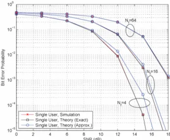
Fig. 1. BEP versus SNR for a single user system with El = 1 and Nj = 4, 16, and 64.
Then, from (12),
Dl
andD2
are distributed as follows:b(l), Dl -D2
is also Gaussian as follows:Dlrvx2M�r
(0) and
D2rvx2M�r(()NJl2)
(18)Dl-D2rvN
(
b(1)()Nf/2, 2u4NfM+2u2()Nf
)
,
(25)Similarly, for
b(l)
=1,
Dl rv X2MN (()NJl2)
""..'.'..L 2 (19)
From (18) and (19), the probability of error can be calculated as
Pe
=P{Dl
>D2Ib(1)
=-I}
=J
(1- ,(!:!.!p., ifIx))
_1
_ e-(x+&Nf
/
2)/
2u2qM:'f)
2u2
x(
0
;;
/2
)
M:,
-jIM:,
_,(
JX
��f
/2
)
dx . (20)Note that
Pe
=P{Dl
>D2Ib(1)
=-I}
is used sinceP{Dl
>D2Ib(1)
=-I}
=P{Dl
�D2Ib(1)
=I}
in (15) due to symmetry.The probability of error expression in (20) is an accurate expression, which can be evaluated numerically, for example, using MATLAB. In order to illustrate the accuracy of this expression, we will compare it against a Gaussian approxima tion. To that aim,
Dl
andD2
can be approximated by Gaussian random variables with the following means and variances [18]:Dl rvN
(
u2N
�
M , u4NfM
)
(21)
N
(
2NfM ()Nf
4
2
)
D2 rv
u -
2
- + -2- , u NfM + 2u ()Nf
(22)(23) (24) for
b(l)
=1.
In addition, for a given binary information symbolThus, from (IS), the probability of error can be expressed as
Pe
� Q(
J2u2
����
2 + ())
)
,
(26)which can also be stated, based on (17), as
p � Q
(
E1Ew
)
e rv
J2u2(NfMu2 + 2E1Ew)
(27)In order to compare the expressions in (20) and (27), simulations and numerical evaluations have been performed. Fig. 1 plots the bit error probability (BEP) versus the signal-to noise ratio (SNR) for different numbers of frames,
Nf.
From the figure, it is observed that, for a constant symbol energy, the performance of the receiver degrades asN f
increases, which is expected from (27). In addition, there is good agreement between the exact theoretical results (obtained from (20)) and the simulation results, whereas the Gaussian approximation in (27) results in inaccurate error values for small values ofNf,
as might be expected.For the scenario in Fig. I, a single path channel is consid ered for simplicity (realistic multi path channels are considered in Section VI) and the integration interval is taken as one pulse duration. Therefore, the degrees of freedom for the chi-square random variable in each frame is small since it is determined by the time duration and bandwidth product [II]. Therefore, the Gaussian approximation becomes accurate only for large
Nf
values since the degrees of freedom of the decision variables are given byMNf/2
as shown in (18) and (19). In practical UWB channels, there can be a large number of multi path components; hence, a larger integration interval can be employed. Therefore, the Gaussian approximation may be accurate in practice.B. Multiuser Case
In this section, the performance of the conventional receiver is analyzed in multiuser environments. Although it is difficult
to obtain a reasonable expression for the exact probability of error in this case, a closed form expression can be obtained based on the Gaussian approximation similarly to that in [14]. Without loss of generality, user 1 is assumed to be the user of interest in a K -user system. Assuming equiprobable information symbols for all users, the probability of error can be expressed as
Pe =2
�
_L
(
P
{
DI-D2:::>0I b(1)=-1,b
}
bE{±l}K-l
+P
{
DI-D2<0I b(1)=-1,b
}
)
,
(28)where
b = [b(2) . . . b(K)]T,
andD
l andD2
are given byDl =
LX�(Bj(b))
andD2 =
LX�(Bj(b)).
(29)j
ESIn the following lemma, the asymptotic normality of
Dl
andD2
is stated.Lemma 1: As
MNf
----* 00,
Dl
andD2
are Gaussiandistributed as follows:
Dl
rv N(
L (0"2
M
+
Bj(b)), L (
2M
0"
4 +
40"2Bj(b))
)
j
ESj
ESD2
rv N(
�
(0"2
M
+
Bj(b)),
�
(
2M
0"
4 +
40"2Bj(b))
)
.
j
ESj
ES (30) Proof: Please see [18].Although Lemma 1 is in the form a Gaussian approxi mation, it is important to note that it differs from common Gaussian approximation approaches that are based on a large number of users. In this scenario, the Gaussian approximation becomes more accurate as
M Nf
increases. In other words, even for a small number of users, the approximation is quite accurate for largel\II N f.
Since
lSI = lSI =
Nf/2,
and the difference of two independent Gaussian random variables is also Gaussian, the termDl -D2
is distributed asThus, the probability of error can be calculated from (28) as in (32), shown at the top of the next page.
Note that for the single user case, that is,
b
= b(l),
(32) reduces to (27) as expected. Although the expression in (32) can be difficult to evaluate for a large number of users, it can be used to obtain probability of error expressions for small numbers of users, which is in fact the case in many practical situations, such as indoor UWB applications [1].V. MAXIMUM-LIKELIHOOD (ML) DETECTOR In order to provide a performance benchmark, the ML detec tor is investigated, and its exact and approximate calculations are discussed in this section. Although the ML receiver can be computationally complex in many cases, it is known to
minimize the probability of error for equally likely symbols; hence, it serves as an optimal receiver.
In the ML detector, the set of information symbols
b
=
[b(1) .. . b(K)]T
is estimated asNf-l
b
=
arg max log
(P
b(
Y))
=
arg max '" log
(Pb(Yj)) ,
b b
j=O
�(33) where
Pb(Yj)
is the probability density function (PDF) of a non-central chi-square random variable and is given byNote that for a given set of binary information symbols
b,
if the signal energy (in the absence of noise) is zero; that is,Bj (b)
= 0,
thenYj
becomes central chi-square distributed. It is also noted that the objective function above can be computationally complex to evaluate. Therefore, the Gaussian approximation can be used to provide a simpler alternative solution.From Lemma 1, it is observed that the Gaussian approxi mation can be employed for large values of
M.
Hence, the PDF ofYj
can be written as1
(Yj _l'j)2( )
- �Pb Yj
=
---eV27fO"j
Jwhere /.Lj and
O"j
are given respectively by/.Lj =
0"
2
M
+
Bj(b)
, andO"j
= 2M0"4 +
40"2Bj(b).
Thus, (33) can be expressed alternatively as
arg max log
(Pb
(y))
b
NJ-l
{
2
}
(y
-/.L.)
=
arg min
L
log(
V27fO"j)
+
J2
Jb
j=O
2
0"
J (35) (36) (37) (38) Note that in order to implement this detector, the channel state information, the TH sequences, and the polarity and or thogonalization codes for all users must be known. Therefore, this detector can be considered only to provide a performance benchmark.VI. SIMULATION RESULTS AND CONCLUSIONS In this section, further simulation results are presented in order to illustrate the results in the previous sections. The UWB pulse
w(t)
is chosen as the second order derivative of the Gaussian pulse [2]; that is,(
4
7ft
2
)
2�12w(t)
= 1 -
Y
e - ---cr/
JE;, ,
(39) where Ep is a scalar chosen to setw(t)
to unit energy and( =
Tc/2.5
determines the pulse width. The bandwidth of the receive filter is5
GHz and the channel statistics are taken from the IEEE 802.15 Aa channel models CM 1 and CM2 [20]. For the considered CM-TR UWB system, the system parameters'"' :c '" .c e IL g W iIi 10° 10-1 10-2 10-3 -'* -Conv. Simu
10-4 , . -0- Cony. Approx. Theo
- B -ML
••••••.•••••• 1\. •• - * -Single User, Simu
· · ·0· · Single User, Approx. Theo ... , ... c ... , ... \.:. 10"
-5 o 5 10
Eh/No (dB)
15 20
Fig. 2. BEP versus Eh/NO for a 2-user system for CMI with Nf = 4, Nc = 250, El = 1, and E2 = 1.
are chosen as
Nf
= 4 andNe
=250,
which correspond to a data rate of Rb =1
Mbitls data rate,Fig. 2 and Fig. 3 plot the BEPs for CMl and CM2 for a two-user CM-TR UWB system. The BEPs are obtained as a function of the SNR defined in terms of
Eh/No,
whereEh
is the energy ofh(t)
given byEh
=fr h2(t)dt
(fi = f,'Vi),
withh(t)
=J El/ (2Nf)
w(t)
andw(t)
being the channel response to the unit energy pulsew(t)
in (39), In the figures, the receiver analyzed in Section IV is denoted as conventional ('Conv.'), and also the error probabilities in the absence of interference users ('Single User') are shown for comparison. In addition, the performance of the ML detector based on (38) is also illustrated,From the plots, good agreement is observed between the theoretical and the simulation results for both single-user and two-user cases, Also, the conventional receiver has signifi cantly worse performance than the ML receiver. However, it has implementation advantages over the ML receiver as discussed previously.
REFERENCES
[I] H. Arslan, Z. N. Chen, and M.-G. Di Benedetto (editors), Ultra Wideband Wireless Communications, Wiley-Interscience, Oct. 2006. [2] Z. Sahinoglu, S. Gezici, and I. Guvenc, Ultra-wideband Positioning
Systems: Theoretical Limits, Ranging Algorithms, and Protocols, Cam bridge University Press, 2008.
[3] M. Z. Win and R. A. Scholtz, "Impulse radio: How it works," IEEE Communications Letters, vol. 2, pp. 36-38, Feb. 1998.
[4] D. Cassioli, M. Z. Win, and A. F. Molisch, "The ultra-wide bandwidth indoor channel: from statistical model to simulations," IEEE Journal on Selected Areas in Communications, vol. 20, pp. 1247-1257, Aug. 2002. [5] Y-P. Nakache and A. F. Molisch, "Spectral shape of UWB signals - influence of modulation format, multiple access scheme and pulse shape," Proc. IEEE Vehicular Technology Conference, vol. 4, pp. 25 10-25 14, Apr. 2003.
[6] S. Gezici, M. Chiang, H. Vincent Poor, and H. Kobayashi, "Optimal and suboptimal finger selection algorithms for MMSE RAKE receivers in impulse radio ultra-wideband systems," Proc. IEEE Wireless Commu nications and Networking Conference, vol. 2 pp. 86 1-866, March 2005.
... '"' :c 10-2 . . • . . . • . •
�
." o • IL .. ' .,'-* -Single User, Simu
'\ .. ,' .
.... \ .... \ \
. . .
•• >�..;...:.: ..
. . ·0 .. Single User, Approx. Theo
10-5l';====�===�=-__ -,---_---.:�-,--___ �
-5 0 5 10
Eh/No (dB)
15 20
Fig. 3. BEP versus Eh/NO for a 2-user system for CM2 with Nf = 4, Nc = 250, El = 1, and E2 = 1.
[7] M. Z. Win and R. A. Scholtz, "On the energy capture of ultrawide band width signals in dense multi path environments," IEEE Communications Letters, vol. 2 pp. 245-247, Sept. 1998.
[8] R. Hoctor and H. Tomlinson, "Delay-hopped transmitted-reference RF communications," Proc. IEEE Conference on Ultra Wideband Systems and Technologies, pp. 265-269, May. 2002.
[9] J. D. Choi and W. E. Stark, "Performance of ultra-wide band communica tions with suboptimal receivers in mUltipath channels," IEEE Journal on Selected Areas in Communications, vol. 20 pp. 1754-1766, Dec. 2002. [ 10] D. L. Goeckel and Q. Zhang, "Slightly frequency-shifted reference ultra wideband (UWB) radio," IEEE Transactions on Communications, vol. 55 pp. 508-519, March 2007.
[II] S. Gezici, "Coded-reference ultra-wideband systems," P roc. IEEE Inter national Con! on Ultra-Wideband, vol. 3, pp. 1 17- 120, Sept. 2008. [ 12] J. Zhang, H.-Y Hu, L.-K Liu, and T-F. Li, "Code-orthogonalized
transmitted-reference ultra-wideband (UWB) wireless communication system," Proc. International Conference on Wireless Communications, Networking and Mobile Computing, pp. 528-532, Sept. 2007. [ 13] A. A. D'Amico and U. Mengali "Code-multiplexed UWB transmitted
reference radio," IEEE Transactions on Communications, vol. 56 pp. 2 125-2132, Dec. 2008.
[ 14] A. A. D'Amico and U. Mengali, "Code-multiplexed transmitted reference UWB systems in a multi-user environment," IEEE Transac tions on Communications, vol. 58, no. 3, pp. 966-974, March 20 10. [ 15] N. Song, M. Wolf, and M. Haardt, "Performance of PPM-based non
coherent impulse radio UWB systems using sparse codes in the presence of multi-user interference," in Proc. IEEE Wireless Communications and Networking Conference (WCNC 2009), Budapest, Hungary, April 2009. [ 16] S. H. Song and Q. T Zhang, "TH-CDMA-PPM with noncoherent detection for low rate WPAN, IEEE Transactions on Wireless Com munications, vol. 7, no. 2, pp. 446-451, Feb. 2008.
[ 17] B. Hu and N. C. Beaulieu, "Exact bit error rate analysis of TH-PPM UWB systems in the presence of multiple-access interference," IEEE Commun. Lett., vol. 7, no. 12, pp. 572-574, Dec. 2003.
[ 18] M. E. Tutay, "Receiver design and performance analysis for code-multiplexed transmitted-reference ultra-wideband systems,"
M.Sc. Thesis, Bilkent University, Aug. 20 10. [Available:
www.ee.bilkent.edu.tr/� gezici/thesisMET pdf]
[ 19] P. A. Humblet and M. Azizoglu, "On the bit error rate of lightwave systems with optical amplifiers," Journal of Lightwave Technology, vol. 9, pp. 1576-1582, Nov. 199 1.