Composite chiral metamaterials with negative
refractive index and high values of the figure of
merit
Zhaofeng Li,1,* Kamil Boratay Alici,1 Humeyra Caglayan,1 Maria Kafesaki,2 Costas M. Soukoulis,2,3 and Ekmel Ozbay1,4
1 Nanotechnology Research Center, and Department of Physics, Bilkent University, Bilkent, 06800 Ankara, Turkey 2 Institute of Electronic Structure and Laser, Foundation for Research and Technology Hellas (FORTH), and
Department of Materials Science and Technology, University of Crete, 71110 Heraklion, Greece 3 Department of Physics and Astronomy and Ames Laboratory, Iowa State University, Ames, Iowa 50011, USA
4 Nanotechnology Research Center, Department of Physics, and Department of Electrical and Electronics Engineering, Bilkent University, Bilkent, 06800 Ankara, Turkey
*
Abstract: A composite chiral metamaterial (CCMM) is designed and
studied both numerically and experimentally. The CCMM is constructed by the combination of a continuous metallic wires structure and a purely chiral metamaterial (CMM) that consists of conjugated Rosettes. For the CMM, only very small, useful bands of negative index can be obtained for circularly polarized waves. These bands are all above the chiral resonance frequencies because of the high value of the effective parameter of relative permittivity ε. After the addition of the continuous metallic wires, which provide negative permittivity, the high value of ε can be partially compensated. Thus, a negative index band for the left circularly polarized wave that is below the chiral resonance frequency is obtained for the CCMM. At the same time, a negative index band for the right circularly polarized wave that is above the chiral resonance frequency is also obtained. Furthermore, both negative index bands correspond to the transmission peaks and have high values of the figure of merit. Therefore, the CCMM design that is proposed here is more suitable than the CMM for the construction of chiral metamaterials with a negative index.
©2012 Optical Society of America
OCIS codes: (160.1585) Chiral media; (310.6628) Subwavelength structures, nanostructures;
(230.5440) Polarization-selective devices.
References and links
1. D. R. Smith, W. J. Padilla, D. C. Vier, S. C. Nemat-Nasser, and S. Schultz, “Composite medium with simultaneously negative permeability and permittivity,” Phys. Rev. Lett. 84(18), 4184–4187 (2000).
2. R. A. Shelby, D. R. Smith, and S. Schultz, “Experimental verification of a negative index of refraction,” Science
292(5514), 77–79 (2001).
3. J. B. Pendry, “Negative refraction makes a perfect lens,” Phys. Rev. Lett. 85(18), 3966–3969 (2000). 4. N. Katsarakis, T. Koschny, M. Kafesaki, E. N. Economou, E. Ozbay, and C. M. Soukoulis, “Left- and
right-handed transmission peaks near the magnetic resonance frequency in composite metamaterials,” Phys. Rev. B
70(20), 201101 (2004).
5. K. Aydin, I. Bulu, and E. Ozbay, “Focusing of electromagnetic waves by a left-handed metamaterial flat lens,” Opt. Express 13(22), 8753–8759 (2005).
6. K. Aydin and E. Ozbay, “Capacitor-loaded split ring resonators as tunable metamaterial components,” J. Appl. Phys. 101(2), 024911 (2007).
7. J. Zhou, T. Koschny, M. Kafesaki, E. N. Economou, J. B. Pendry, and C. M. Soukoulis, “Saturation of the magnetic response of split-ring resonators at optical frequencies,” Phys. Rev. Lett. 95(22), 223902 (2005). 8. M. W. Klein, C. Enkrich, M. Wegener, C. M. Soukoulis, and S. Linden, “Single-slit split-ring resonators at
optical frequencies: limits of size scaling,” Opt. Lett. 31(9), 1259–1261 (2006).
9. V. M. Shalaev, “Optical negative-index metamaterials,” Nat. Photonics 1(1), 41–48 (2007). 10. J. B. Pendry, “A chiral route to negative refraction,” Science 306(5700), 1353–1355 (2004).
11. S. Tretyakov, I. Nefedov, A. Sihvola, S. Maslovski, and C. Simovski, “Waves and energy in chiral nihility,” J. Electromagn. Waves Appl. 17(5), 695–706 (2003).
12. A. V. Rogacheva, V. A. Fedotov, A. S. Schwanecke, and N. I. Zheludev, “Giant gyrotropy due to electromagnetic-field coupling in a bilayered chiral structure,” Phys. Rev. Lett. 97(17), 177401 (2006). 13. H. Liu, D. A. Genov, D. M. Wu, Y. M. Liu, Z. W. Liu, C. Sun, S. N. Zhu, and X. Zhang, “Magnetic plasmon
hybridization and optical activity at optical frequencies in metallic nanostructures,” Phys. Rev. B 76(7), 073101 (2007).
14. T. Q. Li, H. Liu, T. Li, S. M. Wang, F. M. Wang, R. X. Wu, P. Chen, S. N. Zhu, and X. Zhang, “Magnetic resonance hybridization and optical activity of microwaves in a chiral metamaterial,” Appl. Phys. Lett. 92(13), 131111 (2008).
15. N. Liu, H. Liu, S. Zhu, and H. Giessen, “Stereometamaterials,” Nat. Photonics 3(3), 157–162 (2009). 16. M. Decker, M. Ruther, C. E. Kriegler, J. Zhou, C. M. Soukoulis, S. Linden, and M. Wegener, “Strong optical
activity from twisted-cross photonic metamaterials,” Opt. Lett. 34(16), 2501–2503 (2009).
17. B. Wang, T. Koschny, and C. M. Soukoulis, “Wide-angle and polarization-independent chiral metamaterial absorber,” Phys. Rev. B 80(3), 033108 (2009).
18. Z. Li, H. Caglayan, E. Colak, J. Zhou, C. M. Soukoulis, and E. Ozbay, “Coupling effect between two adjacent chiral structure layers,” Opt. Express 18(6), 5375–5383 (2010).
19. B. Wang, J. Zhou, T. Koschny, and C. M. Soukoulis, “Nonplanar chiral metamaterials with negative index,” Appl. Phys. Lett. 94(15), 151112 (2009).
20. S. Zhang, Y.-S. Park, J. Li, X. Lu, W. Zhang, and X. Zhang, “Negative refractive index in chiral metamaterials,” Phys. Rev. Lett. 102(2), 023901 (2009).
21. E. Plum, J. Zhou, J. Dong, V. A. Fedotov, T. Koschny, C. M. Soukoulis, and N. I. Zheludev, “Metamaterial with negative index due to chirality,” Phys. Rev. B 79(3), 035407 (2009).
22. J. Zhou, J. Dong, B. Wang, T. Koschny, M. Kafesaki, and C. M. Soukoulis, “Negative refractive index due to chirality,” Phys. Rev. B 79(12), 121104 (2009).
23. Z. Li, R. Zhao, T. Koschny, M. Kafesaki, K. B. Alici, E. Colak, H. Caglayan, E. Ozbay, and C. M. Soukoulis, ““Chiral metamaterials with negative refractive index based on four “U” split ring resonators,” Appl. Phys. Lett.
97(8), 081901 (2010).
24. R. Zhao, L. Zhang, J. Zhou, T. Koschny, and C. M. Soukoulis, “Conjugated gammadion chiral metamaterial with uniaxial optical activity and negative refractive index,” Phys. Rev. B 83(3), 035105 (2011).
25. R. Zhao, J. Zhou, T. Koschny, E. N. Economou, and C. M. Soukoulis, “Repulsive Casimir force in chiral metamaterials,” Phys. Rev. Lett. 103(10), 103602 (2009).
26. R. Zhao, T. Koschny, E. N. Economou, and C. M. Soukoulis, “Comparison of chiral metamaterial designs for repulsive Casimir force,” Phys. Rev. B 81(23), 235126 (2010).
27. J. D. Jackson, Classical Electrodynamics, 3rd ed. (Wiley, 1998). 28. J. A. Kong, Electromagnetic Wave Theory (EMW Publishing, 2008).
29. R. Zhao, T. Koschny, and C. M. Soukoulis, “Chiral metamaterials: retrieval of the effective parameters with and without substrate,” Opt. Express 18(14), 14553–14567 (2010).
30. D. R. Smith, S. Schultz, P. Markos, and C. M. Soukoulis, “Determination of effective permittivity and permeability of metamaterials from reflection and transmission coefficients,” Phys. Rev. B 65(19), 195104 (2002).
31. Z. Li, K. B. Alici, E. Colak, and E. Ozbay, “Complementary chiral metamaterials with giant optical activity and negative refractive index,” Appl. Phys. Lett. 98(16), 161907 (2011).
32. N. Liu, S. Kaiser, and H. Giessen, “Magnetoinductive and electroinductive coupling in plasmonic metamaterial molecules,” Adv. Mater. (Deerfield Beach Fla.) 20(23), 4521–4525 (2008).
1. Introduction
Metamaterials are artificially structured materials that can be composed of dielectric elements or structured metallic components. Metamaterials may possess electromagnetic properties that do not exist in natural materials. Since Smith et al. experimentally demonstrated negative index metamaterials (NIMs) [1, 2] and Pendry proposed that a perfect lens can be realized with NIMs [3], studies regarding NIMs have attracted much attention and effort from scientific researchers [4–6]. Usually, NIMs are obtained by adjusting the permittivity and permeability of the metamaterial to be negative simultaneously. Although negative permeability can be easily obtained in the microwave frequency range, that is not the case in the optical frequency range [7–9]. Recently, it was proposed that a negative index can also be achieved alternatively through a chiral route [10, 11], and since then chiral metamaterials (CMMs) have attracted much attention. In fact, besides for the negative index, CMMs can also possess other interesting properties, such as the giant optical activity and circular dichroism, which may find their way into optical applications [12–24]. It is even reported that CMMs can be used to tune the Casimir force [25, 26]. In all of these cases, a strong chirality is desired.
A CMM lacks any mirror symmetry, so that there is cross-coupling between the electric and magnetic fields at the resonance. Consequently, the degeneracy of the two circularly
polarized waves is broken, i.e., right circularly polarized (RCP, +) waves and left circularly polarized (LCP, -) waves have different refractive indices. The chirality parameter κ describes the strength of the cross-coupling effect, so that the constitutive relations of a chiral medium is given by. 0 0 / , / i c D E i c B H ε ε κ κ µ µ − = (1)
where ε0 and µ0 are the permittivity and permeability of vacuum. ε and µ are the relative
permittivity and permeability of the chiral medium. c is the speed of light in vacuum. Assuming a time dependence of e-iωt, the RCP ( + ) wave and LCP (-) wave are defined as
ɵ ɵ
0
(1 / 2) ( )
E±= E x∓i y [27]. The refractive indices for RCP and LCP waves can be expressed as n± = ± [28], where n κ n= εµ . When κ is large enough, either n+ or n− becomes
negative. At the same time, both RCP and LCP waves have the same impedance of
0
/ /
z z = µ ε , where z0 is the impedance of the vacuum.
However, when one investigates the negative index CMMs that have been reported so far [19–24], it is found that when a large chirality κ is obtained, a large relative permittivity ε (or large relative permeability µ) coexists below the frequency of chiral resonances. Consequently, the absolute value of chirality κ is always less than n in the frequency range below the chiral resonances. Therefore, the negative index can only happen in the frequency range above the resonance, where the relative permittivity ε (or relative permeability µ) is very low and/or even in the negative region. In this paper, we propose a composite chiral metamaterial (CCMM) that consists of chiral components and continuous metallic wires. By using continuous metallic wires, the large permittivity below the resonance is compensated partially, which makes n become smaller than κ below the frequency of resonance. Therefore, a negative index can be realized in the frequency region below the chiral resonances.
2. The design of the composite chiral metamaterial and the results
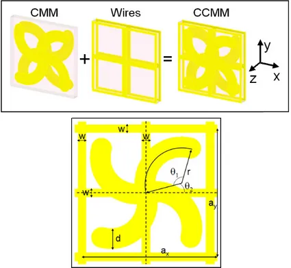
Here, a conjugated Rosettes structure (Fig. 1) is used as the chiral component to obtain chirality, and this conjugated Rosettes structure is somewhat similar to the structure reported earlier [24]. We select a conjugated structure because it has a relatively large chirality and at the same time a relatively weak electric resonance [26]. Figure 1 shows the schematics of the construction of the unit cell of the CCMM. The copper conjugated Rosettes and continuous wires are patterned on the opposite sides of a Teflon dielectric board with a thickness of 2 mm. The dielectric constant of the Teflon board is εr = 2.08 with a dielectric loss tangent of
0.0004. The detailed dimensions of the structure can be found in Fig. 1 and its caption. In order to study the effect of additional continuous metallic wires on the CMM structure that only consists of conjugated Rosettes, we investigated both the CMM and the CCMM in the numerical simulations and experiments.
The simulation works were carried out by using a commercial software package (CST microwave studio), wherein the finite integration technique was applied. During the simulations, the periodic boundary conditions were applied to the x and y directions (transverse direction), and the absorbing boundary conditions were applied to the z direction (propagation direction). In the experiment, we fabricated both the CMM and CCMM structures with a dimension of 18 by 18 unit cells. The transmission coefficient was measured by an HP-8510C network analyzer with two standard horn antennas. In order to study the transmission behaviors of the chiral structures, in our simulation and experimental works, a linearly polarized electromagnetic wave (E field in the x direction) is incident on the chiral structure. On the other side of the structure, we measured the transmitted field in the x and y polarizations (Txx and Tyx). Due to the fourfold rotational symmetry, circular polarization
conversion is absent. The transmission of circularly polarized waves can be calculated from the linear transmission coefficients Txx and Tyx [21, 22], T Txx iTyx
± = ±
electromagnetic wave transmitted, the polarization azimuth rotation angle θ can be calculated as θ=[arg(T+) arg(− T−)] / 2 . The ellipticity of the transmitted wave is defined as
arctan[(T T ) / (T T )]
η= + − − + + −
[27], which also measures circular dichroism.
Fig. 1. The schematics of the construction of the CCMM by the combination of a CMM and a structure of continuous metallic wires, and the dimensions of the designed structure. The geometric parameters are given by ax = ay = 19 mm, r = 5.4 mm, θ1 = 120°, θ2 = 15°, w = 1.2
mm, and d = 3.0 mm. The copper layer has a thickness of 0.03 mm.
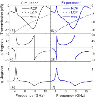
Firstly, we shall show the properties of the CMM that only consists of conjugated Rosettes. Figures 2(a) and 2(b) show the simulated and measured transmission spectra for the CMM. The transmission spectra of RCP and LCP waves are almost the same. This is because the loss of the dielectric material (Teflon) here is very small. For the purpose of a good comparison, in Figs. 2(a) and 2(b), we also show the transmission spectra for the structure of continuous metallic wires. Figures 2(c)–2(f) show the simulated and experimental results of the polarization azimuth rotation angle θ and the ellipticity η. From the above results, it is clear that there are two resonances related to the chirality. One resonance happens at the frequency f = 4.23 GHz, which corresponds to a narrow high transmission band. The other resonance is at f = 7.82 GHz, which corresponds to a wide band gap. Due to the low loss of the Teflon material, the ellipticity η of the transmitted wave is very small. η remains less than 1.5 degree in the whole frequency range. For a linearly polarized incident wave, the transmitted wave is still highly linearly polarized over the whole frequency range but with a rotated angle θ. The azimuth rotation angle θ is as large as 88 degrees at 4.23 GHz, which means that the rotation angle θ per wavelength reaches more than 3000°/λ.
Fig. 2. Simulation and experimental results for the CMM and the structure of metallic wires. (a) and (b) show the transmission spectra of RCP and LCP waves for the CMM and the structure of metallic wires. (c), (d), (e), and (f) show the polarization azimuth rotation angle θ and the ellipticity angle η of the transmitted wave when a linearly polarized wave is incident on the CMM.
Fig. 3. The retrieved effective parameters of the CMM and the structure of metallic wires based on the simulation and experimental data. (a) and (b) are the real parts of the refractive index n and chirality κ. (c) and (d) are the real parts of the relative permittivity ε of the CMM and the structure of metallic wires. (e) and (f) are the real parts of the relative permeability µ of the CMM.
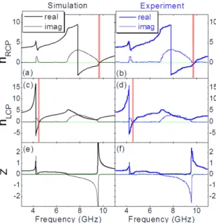
Fig. 4. The retrieved effective parameters of the CMM based on the simulation and experimental data. (a), (b), (c), and (d) are the real and imaginary parts of the refractive index of RCP and LCP waves. The shadowed regions show the negative index bands with small imaginary parts and, therefore, are suitable for the construction of bulk chiral metamaterials with a negative index. (e) and (f) show the impedance z.
Figures 3 and 4 show the retrieved effective parameters (the real parts of n, κ, ε, µ, and the real and imaginary parts of n+, n- and the impedance of z) based on the simulated and
experimental data of the transmission and reflection for one layer of the CMM [24, 29, 30]. In the retrieval process, the effective thickness of the CMM is assumed to be 3.0 mm along the wave propagation direction. From Figs. 3(a) and 3(b), it is clear that n remains positive over the whole frequency range. However, it is seen from Figs. 4(a)–4(d), due to the relation of
n± = ± , the strong chirality κ (in Fig. 3) can push the refractive index of an RCP (LCP) n κ
wave to be negative above the resonant frequency of 7.82 (4.23) GHz. Nevertheless, as we have pointed out earlier, below the resonant frequencies, due to the high value of ε and/or µ, the absolute value of κ is less than n. Therefore, one cannot obtain a negative index below the resonant frequencies. Furthermore, in the regions just above the frequency of the chiral resonances, both n+ and n- possess a high value of imaginary parts. Therefore, the figure of
merit [-Re(n)/Im(n)] of the negative refractive index deteriorates in these regions. Only those small regions that are indicated by shadowed regions in Figs. 4(a)–4(d) can be useful in the construction of negative index chiral metamaterials. For the RCP wave, this useful negative index band is from 9.56 to 9.71 GHz, and the maximum figure of merit is 8.4. For the LCP wave, the useful negative index band is from 4.42 to 4.53 GHz, and the maximum figure of merit reaches 6.6.
In Fig. 3(c) and 3(d), we also show the effective parameter of ε for the purely metallic wire structure. It is clear that in the whole frequency range, ε remains negative. By adding this structure of continuous metallic wires to the original CMM, we constructed the CCMM, as shown in Fig. 1. Figures 5(a) and 5(b) show the simulated and measured transmission spectra for the CCMM. The transmission spectra of RCP and LCP waves are again almost the same due to the low loss of the dielectric material (Teflon). Figures 5(c)–5(f) show the simulated and experimental results of the polarization azimuth rotation angle θ and the ellipticity η. There are two resonances on the curve of the chirality. One happens at the frequency f = 5.36 GHz. Below and above this frequency, there are two high transmission peaks (peak 1 centered at f = 5.16 GHz, and peak 2 centered at f = 6.20 GHz). The other resonance is at f = 8.70 GHz,
which corresponds to a big band gap. Consequently, the resonance at f = 5.36 GHz should be more useful for the construction of chiral metamaterials.
Fig. 5. Simulation and experimental results for the CCMM. (a) and (b) show the transmission spectra of RCP and LCP. (c), (d), (e), and (f) show the polarization azimuth rotation angle θ and the ellipticity angle η of the transmitted wave when a linearly polarized wave is incident on the CCMM.
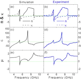
Fig. 6. The retrieved effective parameters of the CCMM based on the simulation and experimental data. (a) and (b) are the real parts of the refractive index n and chirality κ. (c) and (d) are the real parts of the relative permittivity ε. (e) and (f) are the real parts of the relative permeability µ.
In comparing with Figs. 2(c) and 2(d), the polarization azimuth rotation angle θ in Figs. 5(c) and 5(d) at the lower frequency resonance is reversed. The ellipticity η is still small.
η remains less than 1 degree in the whole frequency range except for the frequency range
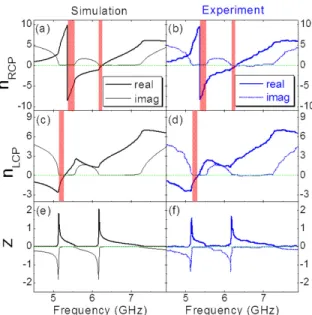
Fig. 7. The retrieved effective parameters of the CCMM based on the simulation and experimental data. (a), (b), (c), and (d) are the real and imaginary parts of the refractive index of RCP and LCP waves. The shadowed regions show the negative index bands with small imaginary parts and, therefore, are suitable for the construction of bulk chiral metamaterials with a negative index. (e) and (f) show the impedance z.
Figures 6 and 7 show the retrieved effective parameters (the real parts of n, κ, ε, µ, and the real and imaginary parts of n+, n- and the impedance of z) based on the simulated and
experimental data of the transmission and reflection for one layer of the CCMM. In the retrieval process, the effective thickness of the CCMM is assumed to be the same (3.0 mm) as that of the CMM. From Figs. 6(a) and 6(b), it is clear that above the lower frequency resonance (f = 5.36 GHz), there is a region from 5.36 to 5.58 GHz where n is negative. Moreover, there is a big difference between Fig. 6(a) and Fig. 3(a). Below the frequency of resonance (f = 5.36 GHz), κ is larger than n in the absolute values in Fig. 6(a). This is not the case in Fig. 3(a). From Figs. 6(c) and 6(d), it is also seen that due to the existence of the continuous metallic wires, there exists a plasmonic frequency f = 5.13 GHz below which ε is negative. Since the resonance at f = 8.70 GHz corresponds to a big band gap, the frequency range around there is not suitable for the construction of chiral metamaterials. Therefore, in the following, we will concentrate on the properties around the lower frequency resonance at f = 5.36 GHz, as shown in Fig. 7. Comparing Figs. 6(a) and 6(b) with Figs. 7(a) and 7(b), it is seen that, due to the relation of n+ = + , the strong chirality κ makes the originally negative n κ
index band of the RCP wave wider and deeper above the resonant frequency of 5.36 GHz. In the frequency range from 5.36 to 5.58 GHz, the maximum figure of merit can reach more than 50. In the frequency range from 5.58 to 6.17 GHz, the CCMM meets a small forbidden band [as can be also seen from the impedance data of Figs. 7(e) and 7(f)], and the figure of merit becomes lower. In the frequency range from 6.17 to 6.25 GHz, the CCMM has small negative index values, and this band corresponds to the transmission peak 2 centered at f = 6.20 GHz (Fig. 5). Now let us discuss the case of the LCP wave. Comparing Figs. 6(a) and 6(b) with Figs. 7(c) and 7(d), it is seen that, due to the relation of n−= − , the strong chirality κ has n κ
pushed the refractive index of the LCP wave from positive to negative values below the frequency of 5.29 GHz. Consequently, the LCP wave has a negative index band from the plasmonic frequency 5.13 GHz to 5.29 GHz. In this negative index band, the maximum figure of merit reaches 18, and this band corresponds to the transmission peak 1 centered at f = 5.16 GHz (Fig. 5). The figure of merit obtained here for the CCMM is remarkably higher than
those chiral metamaterials reported earlier [19–24] even when the lossy properties of the dielectric layer are taken into account. Those negative index bands with high values of the figure of merit are indicated with shadowed regions in Figs. 7(a)–7(d), and these bands can be useful in the construction of negative index chiral metamaterials. The above situation (negative index is obtained below the chiral resonant frequency) of the CCMM is somewhat similar to that of the complementary chiral metamaterials we studied very recently [31].
3. Discussions
If one compares Figs. 2(c) and 2(d) with Figs. 5(c) and 5(d), it can be found that besides for the reverse of the θ around the lower frequency resonance, the frequencies of both chiral resonances of the CCMM are shifted to higher frequencies compared to that of the CMM. In the following, we will discuss these two phenomena briefly.
The reverse of the θ around the lower frequency resonance can be understood qualitatively as the following. For both the CMM and CCMM, the RCP and LCP waves are the eigenwave functions. For the CMM, below (above) the lower frequency resonance, the refractive index of the RCP wave is smaller (larger) than that of the LCP wave. This results in the phase difference of the transmitted RCP and LCP waves. According to the formula
[arg(T ) arg(T )] / 2
θ = + − −
, one obtains negative (positive) values of θ below (above) the lower frequency resonance of the CMM. Then, by adding the continuous metallic wires structure, we constructed the CCMM. Due to the addition of the continuous metallic wires, the
κ curve changes from antiresonant shape to resonant shape around the lower frequency
resonance of chirality. Consequently, below (above) the lower frequency resonance of CCMM, the refractive index of RCP wave is now larger (smaller) than that of LCP wave. As a result, one obtains positive (negative) values of θ below (above) the lower frequency resonance of the CCMM. Nevertheless, this situation does not happen around the resonances of higher frequencies and, therefore, the θ remains the same direction for the CMM and CCMM here.
Fig. 8. The simulation results of the transmission spectra Tyx for the CMM and CCMM around
Fig. 9. The current distributions driven by the linear incident wave polarized in the x direction. (a) corresponds to the transmission peak of Tyx for the CMM (Fig. 8). (b) and (c) correspond to
the transmission peaks of Tyx for the CCMM at lower and higher frequencies (Fig. 8),
respectively. Those current flows with relatively larger strength are indicated by the blue and black arrows. The solid (dotted) arrows represent the currents on the front (back) copper layer. The thickness of the blue and black arrows represents approximately the relative current strength.
In order to understand the phenomenon of blue shift of the resonances, we now study the current modes for the chiral resonances for both the CMM and CCMM. Since the higher frequency resonance in CCMM corresponds to a big band gap, for practical purposes we only discuss the current modes around the lower frequency resonances in the following. Figure 8 shows the simulation results of the transmission spectra of Tyx for both the CMM and CCMM
around the lower frequency resonances. It can be seen that, for the curve of the CMM, there is only one transmission peak that corresponds to the transmission peak of the RCP and LCP waves [shown in Fig. 2(a)]. However, for the curve of the CCMM, there are two transmission peaks that correspond to the two transmission peaks of the RCP and LCP waves [shown in Fig. 5(a)]. Figure 9(a) shows the current distributions of the CMM driven by an incident wave linearly polarized in the x direction at the frequency of the Tyx transmission peak (see Fig. 8).
Figures 9(b) and 9(c) show the current distributions of the CCMM driven by the same incident wave at the frequencies of the lower and higher Tyx transmission peaks (see Fig. 8),
respectively. Those current flows with relatively larger strength are indicated by the blue and black arrows. The solid (dotted) arrows represent the currents on the front (back) copper layer. The thickness of the blue and black arrows represents approximately the relative current strength. The current flows of the CCMM are much more complicated than that of the CMM. Comparing Figs. 9(b) and 9(c) with 9(a), it is seen that, besides for the basic current flows (blue lines) in the conjugated Rosettes, there are other current flows (black lines) due to the existence of the continuous metallic wires. These new current flows also result from the inductance-capacitance (LC) resonance. The coupling between the basic resonances of the conjugated Rosettes and the new LC resonances results in the two transmission peaks on the curve of Tyx for the CCMM. It is noteworthy that the coupling mechanism here includes
the resulted chiral resonances of the CCMM are shifted to higher frequencies compared to that of the CMM.
4. Conclusions
In conclusion, we have designed and studied a CCMM both numerically and experimentally. The CCMM is composed of a continuous metallic wires structure and a CMM structure that consists of conjugated Rosettes. For the CMM, only a very small useful band of negative index above the chiral resonances can be obtained because of the high value of the effective parameter ε. After the addition of the continuous metallic wires, which provides negative permittivity, the high value of the effective parameter ε can be partially compensated. Thus, a negative index band for the LCP wave is obtained below the chiral resonance for the CCMM. At the same time, a negative index band for the right circularly polarized wave that is above the chiral resonance frequency is also obtained. Furthermore, both negative index bands correspond to the transmission peaks and have high values of the figure of merit. Therefore, the CCMM proposed here is more suitable for the construction of negative index chiral metamaterials.
Acknowledgments
This work is supported by the projects DPT-HAMIT, ESF-EPIGRAT, EU-N4E, NATO-SET-181 and TUBITAK under Project Nos., 107A004, 107A012, 109E301. One of the authors (E.O.) also acknowledges partial support from the Turkish Academy of Sciences.