IEEE PHOTONICS TECHNOLOGY LETTERS, VOL. 10, NO. 9, SEPTEMBER 1998 1343
Optical Restoration at the
Wavelength-Multiplex-Section Level in WDM Mesh Networks
Ezhan Karasan,
Member, IEEE,and Evan Goldstein,
Member, IEEEAbstract— In the presence of rapidly growing demand, long-haul multiwavelength lightwave networks face the increasingly critical task of not only transporting large traffic volumes, but also of restoring them in the event of failures. This may be naturally done in two distinct ways: by rerouting individual wavelengths (wavelength-paths), or by rerouting full bundles of multiplexed wavelengths (wavelength-multiplex sections). We here evaluate the prospects for restoration at the multiplex-section level in national-scale long-haul wavelength-division-multiplexed mesh networks. The approach is found to offer the potential of substantial economic benefits, given current transponder costs. These benefits will largely vanish, however, if transponder costs decline by an order of magnitude.
Index Terms— Long-haul networks, optical restoration, wavelength-division multiplexing, wavelength-multiplex section, wavelength path.
I. INTRODUCTION
I
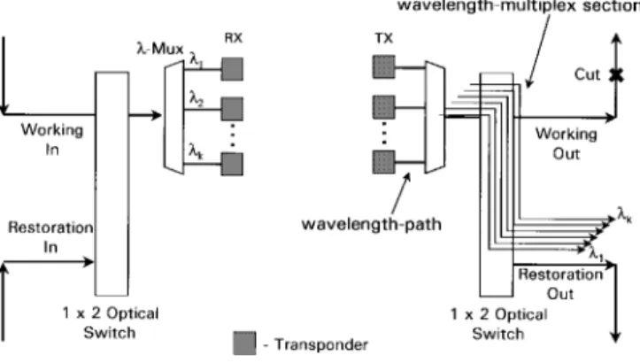
N MULTIWAVELENGTH lightwave networks, there are two fundamentally divergent ways of restoring failures, dis-tinguished by the locations at which one places the restoration-switching elements. One approach is to respond to failures by rerouting individual wavelengths, or wavelength paths (WP). This is achieved by placing switching elements on the “node side” of the network’s wavelength-multiplexers, where they operate only on single-wavelength paths [1], [2]. The various affected wavelengths in a failed fiber may then be rerouted over a variety of restoration routes. Alterna-tively, one can respond to failures by rerouting full sections of wavelength-multiplexed signals, or wavelength-multiplexsections (WMS’s), as depicted in Fig. 1. We here examine
the benefits of restoration at the WMS level. We focus in particular on the cost of such an approach, compared with WP-level restoration, when applied to national-scale long-haul wavelength-division-multiplexed (WDM) networks.
WMS-level restoration in general offers two strengths, in-dependent of the network’s geographical scale. First, traffic is restored in large bundles (full WMS’s), thus reducing both computational complexity and restoration switch-fabric size. Second, restoration is carried out “on the network side” of the wavelength-multiplexer, thus avoiding the expense of duplicated transmitter and receiver line cards.
Manuscript received December 8, 1997; revised March 26, 1998. E. Karasan was with AT&T Laboratories-Research, Newman Springs Laboratory, Red Bank, NJ 07701 USA. He is now with the Department of Electrical Engineering, Bilkent University, Ankara 06533, Turkey.
E. Goldstein is with AT&T Laboratories-Research, Newman Springs Lab-oratory, Red Bank, NJ 07701 USA.
Publisher Item Identifier S 1041-1135(98)06282-X.
Fig. 1. WMS-level restoration versus WP-level restoration.
However, WMS-level restoration also faces three obstacles: 1) due to its coarse-grained nature, the approach necessarily uses restoration capacity less efficiently than do WP-level al-ternatives; 2) WMS-level approaches create optically transpar-ent (unregenerated) domains within which it will be difficult to deploy multivendor transmission equipment; 3) WMS-level restoration paths, being both unregenerated and long in reach, will require the insertion of additional regeneration in order to satisfy transmission-engineering constraints. Thus, in general, restoring at the WP-level economizes on transmission facilities, including fiber amplifiers, while restoring at the WMS-level economizes on the aggregate costs of transmitters and receivers as well as cross-connects.
In this letter, we address these limitations, and present some optimization methods for use in the design of networks with WMS-level restoration. We also estimate the quantitative consequences of the equipment tradeoff noted above, and de-termine the conditions under which the two broad approaches to WDM restoration offer cost advantages.
II. NETWORK ASSUMPTIONS
We examine a WDM mesh network whose topology is representative of the national-scale long-haul network, with approximately 450 switching offices (nodes) interconnected by 550 links. The links employ optical transport systems (OTS) supporting eight wavelengths, each modulated at 2.5 Gb/s. Both the transmit and receive sides of the OTS are assumed to terminate on transponders—the emerging class of optoelec-tronic converters with clock recovery that provide adaptation of 1.55- m long-haul signals to standard 1.3- m cross-office interfaces [3]. Such transponders thus arrest accumulating performance-degradations; provide the open, nonproprietary interfaces that permit multivendor interworking; and offer
1344 IEEE PHOTONICS TECHNOLOGY LETTERS, VOL. 10, NO. 9, SEPTEMBER 1998
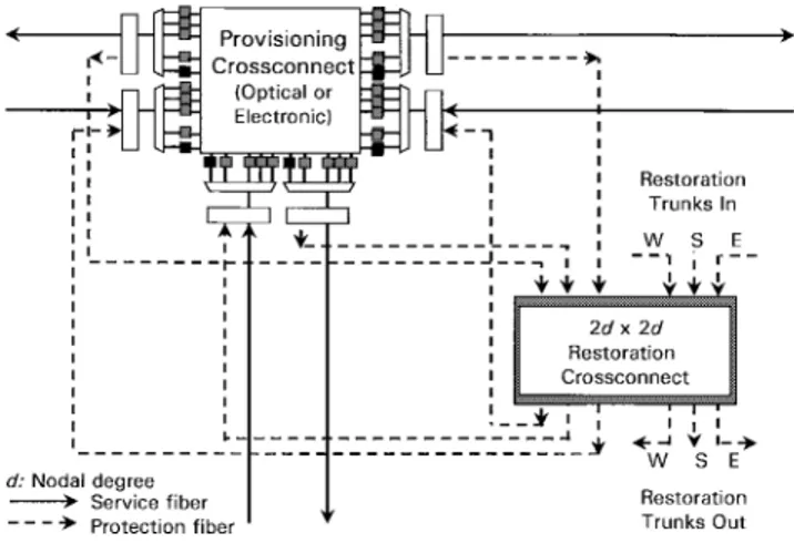
Fig. 2. Sharing of restoration facilities at the WMS level.
a means of carrying out the performance-monitoring and fault-localization that are essential in deployed networks [4]. Transmission-engineering rules are assumed to permit 360-km transmission reach for systems built on 120-360-km amplifier spacings, and 560-km reach for systems built on 80-km repeater spacings. The network is assumed to support traffic projections for the year 2002.
In the WMS-level approach, OTS failures are detected by transponders, and result in reconfiguration of WMS-level restoration crossconnects, which then provide an alternate path between end-points of the failed OTS. The restoration cross-connect at each office, as shown in Fig. 2, has a size of , where is the number of optical transport systems terminating at this office. The restoration crossconnect can connect any of the failed service fibers to either eastbound, westbound, or southbound restoration facilities. These crossconnects are configured to allow the restoration facilities to be shared among multiple OTS’s.
By contrast, we assume that WP-level restoration reroutes each affected connection between its end-points employing what has come to be called end-to-end or source-based rerout-ing [5]. We consider only srerout-ingle OTS failures, and assume that any such failure must be restorable.
III. NUMERICAL RESULTS
Under the above assumptions, WMS-level restoration is, as expected, found to be wasteful of transmission facilities. It on average requires 1.27 km of restoration fiber for each km of service fiber for the national-scale mesh network. WP-level restoration, by contrast, consumes 0.54 restoration kilometer per service kilometer. This finding is consistent with previous studies of WP-level restoration using end-to-end rerouting [1], [2]. The reason for this difference is granularity. WP-level restoration is able to utilize capacity more efficiently both because it can extract restoration capacity from underused service fibers, and because it can employ bifurcated routing techniques.
In addition, WMS-level restoration consumes additional regenerators, used to satisfy transmission-engineering rules on the long WMS restoration paths. We assume that these regen-erators can only be placed at the offices. For the national-scale
network outlined above, an average of 1.1 regeneration points are required in systems built on 80-km repeater spacings, and 2.1 such points per restoration path in systems built on 120-km repeater spacings.
These numbers can be reduced, however, by engineering the network so as to allow restoration paths corresponding to link-disjoint service OTS’s to share regenerators. We employed a greedy algorithm to increase the sharing of regenerator locations, subject to transmission-engineering constraints. The algorithm starts by assigning a regenerator to the location that can be shared by the largest number of paths. For those paths which have a regenerator assignment that contains the selected location, all other assignments which do not include the selected node are discarded. The algorithm continues to select regenerator locations by assigning them to the location with largest sharing until, eventually, all paths satisfy transmission-engineering rules. Further details are shown in the Appendix. When the greedy algorithm is applied to WMS-level restora-tion, one obtains a 31% reduction in regeneration points for systems employing a 120-km repeater spacing. By contrast, this declines to a 19% reduction for systems with 80-km spacings. The improvement is larger for 120-km spacings because one has more alternatives for assigning regeneration points to a given path, and thus more options for sharing. Due to the problem’s large size, it is not known how close the greedy algorithm comes to providing optimal regenerator-sharing solutions.
On the other hand, WP-level restoration requires transpon-ders at the receive and transmit sides of each office traversed by the restoration path, and it is this approach that con-sumes very large numbers of transponders. By comparison, WMS-level restoration reduces the number of transponders on restoration paths by 89% at 80-km repeater spacings, and by 83% at 120-km repeater spacings.
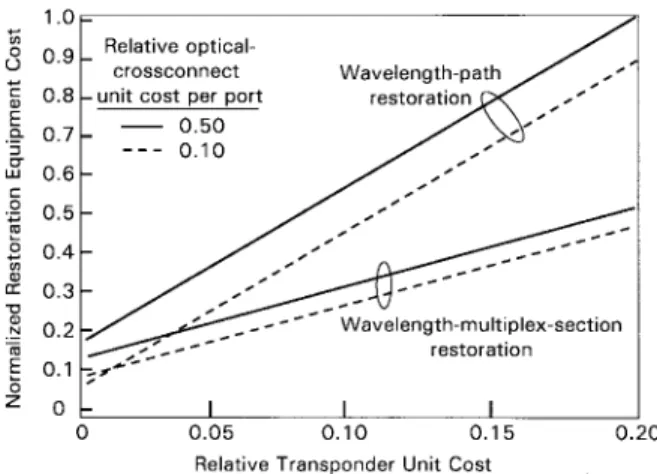
Given the above results, together with current equipment costs, the relative economic merits of WMS-level and WP-level end-to-end restoration are readily calculated. Equipment costs are normalized to the current cost of an optical amplifier . Link costs include only the costs of lighting, with optical amplifiers, a fiber that is presumed to be already available. The normalized cost of the optical cross-connect is expected to fall between 0.5 per port (conservative) and 0.1 per port (aggressive) [6]. We assume that the same basic technology is used for both the WP-level and WMS-level cross-connect, so that costs per port for the two approaches are identical. With these assumptions, the total network restoration equipment cost is plotted in Fig. 3 as a function of the unit transponder cost per port. Total cost is normalized by the cost of the most costly system plotted (WP-level restoration with unit transponder and cross-connect port costs of 0.2 and 0.5, respectively).
At current transponder costs of roughly 0.4, aggregate system cost is seen to be utterly dominated by the transponders. Thus, WMS-level restoration currently offers the promise of substantial cost advantages. However, should transponder unit costs drop by an order of magnitude, as miniaturization trends would appear to suggest, this advantage largely disappears. In this case, the operational liabilities of WMS-level restoration, alluded to earlier, would likely force its abandonment.
KARASAN AND GOLDSTEIN: OPTICAL RESTORATION AT WMS LEVEL IN WDM MESH NETWORKS 1345
Fig. 3. Normalized restoration equipment cost as a function of unit transpon-der cost. The current relative transpontranspon-der unit cost is approximately 0.4.
It should be noted that the above economic comparison assumes the availability, for free, of unutilized deployed fiber. When this assumption is not valid, WP-level restoration offers very large additional cost advantages, since it requires significantly fewer fibers for restoration.
IV. SUMMARY
In WDM mesh networks, one can carry out restoration in two fundamentally divergent ways: by restoring individual WP’s, or by restoring full WMS’s. The two approaches offer largely orthogonal sets of virtues. When they are applied to national-scale long-haul networks, however, their relative costs depend strongly on the relative costs of transponders, optical cross-connects, fiber, and fiber amplifiers. At current transponder unit costs, WMS-level restoration appears to offer the prospect of significant economic benefits in national-scale WDM mesh networks. These benefits will largely vanish, however, if transponder unit costs should decline by an order of magnitude.
APPENDIX
Here, we provide details of the greedy algorithm used to reduce the number of restoration-path regenerators needed by WMS-level restoration. The node with largest sharing is
found by solving the maximum independent set problem [7] for graphs constructed for each node as follows.
In the graph for node , each vertex corresponds to a regen-erator location assignment which has a regenregen-erator assigned to node . There is an edge between vertices that correspond to different regenerator assignments for the same restoration path. The maximum independent set in a graph is the largest set of vertices that have no edges between them, i.e., it is the largest set of regenerator assignments that include node and that correspond to different restoration paths. The steps of the algorithm are described below.
Regenerator Location Algorithm:
Step 1) Enumerate the set of all possible regenerator
loca-tion assignments for each path.
Step 2) For each node, find the maximum number of paths
that can be assigned to a shared regenerator (max-imum independent set).
Step 3) Assign a regenerator to the node that is shared by
the largest number of paths.
Step 4) For paths which have at least one regeneration
as-signment that includes the selected node, delete all the regenerator assignments which do not contain the selected node.
Step 5) IFall paths are assigned a complete set of regener-ators,STOP. ELSE, GO TOStep 2.
REFERENCES
[1] N. Nagatsu, S. Okamoto, and K. Sato, “Optical path cross-connect system scale evaluation using path accommodation design for restricted wavelength multiplexing,” IEEE J. Select. Areas Commun., vol. 14, pp. 893–902, 1996.
[2] Y. Hamazumi, N. Nagatsu, S. Okamoto, and K. Sato, “Number of wavelengths required for constructing optical path networks considering restoration,” Electron. Commun. Jpn., vol. 78, pt. 1, pp. 30–41, 1995. [3] GR-253-CORE, Synchronous Optical Network (SONET) Transport
Sys-tems: Common Generic Criteria, Bellcore, issue 2, Dec. 1995. [4] R. W. Tkach, E. L. Goldstein, J. A. Nagel, and J. L. Strand,
“Fundamen-tal limits of optical transparency,” in Proc. Optical Fiber Communication Conf., San Jose, CA, Feb. 1998.
[5] J. Anderson, B. T. Doshi, S. Dravida, and P. Harshavardhana, “Fast restoration of ATM networks,” IEEE J. Select. Areas Commun., vol. 12, pp. 128–138, 1994.
[6] MONET Quart. Rep., Dec. 1996, unpublished.
[7] M. S. Garey and D. S. Johnson, Computers and Intractability: A Guide to the Theory of NP-Completeness. New York: Freeman, 1979.