Magnetic Resonance Technologies Based on
Reverse Polarization for Image-Guided
Interventions
A THESIS
SUBMITTED TO THE DEPARTMENT OF ELECTRICAL AND
ELECTRONICS ENGINEERING
AND THE INSTITUTE OF ENGINEERING AND SCIENCE
OF BILKENT UNIVERSITY
IN PARTIAL FULFILLMENT OF THE REQUIREMENTS
FOR THE DEGREE OF
DOCTOR OF PHILOSOPHY
By
Haydar Çelik
October, 2010
I certify that I have read this thesis and that in my opinion it is fully adequate, in scope and in quality, as a thesis for the degree of doctor of philosophy.
Prof. Dr. Ergin Atalar (Supervisor)
I certify that I have read this thesis and that in my opinion it is fully adequate, in scope and in quality, as a thesis for the degree of doctor of philosophy.
Prof. Dr. Ayhan Altıntaş
I certify that I have read this thesis and that in my opinion it is fully adequate, in scope and in quality, as a thesis for the degree of doctor of philosophy.
I certify that I have read this thesis and that in my opinion it is fully adequate, in scope and in quality, as a thesis for the degree of doctor of philosophy.
Assoc. Prof. Dr. Vakur B. Ertürk
I certify that I have read this thesis and that in my opinion it is fully adequate, in scope and in quality, as a thesis for the degree of doctor of philosophy.
Assist. Prof. Dr. Ömer İlday
Approved for the Institute of Engineering and Sciences:
Prof. Dr. Levent Onural
ACKNOWLEDGMENTS
It is my pleasure to express my sincere gratitude to my supervisor, Prof. Ergin Atalar, whose expertise, understanding, and patience, added considerably to my graduate experience. I appreciate his vast knowledge and skill in all areas of MRI. I am deeply indebted to him.
I would like to thank the members of my thesis committee, Prof. Ayhan Altıntaş, Prof. Nevzat G. Gençer, Assoc.Prof. Vakur B. Ertürk, and Assist. Prof. Ömer İlday for reading and commenting on this thesis.
I am obliged to thank my co-researchers Dr.Namık Şengezer, Doğaç Gülnerman, Davut İbrahim Mahçiçek, Burak Akın.
I am grateful to Emre Kopanoglu for their valuable discussions. I am also grateful to Volkan Acikel, Ozay Hirlakoglu Prof.Dr. Turgut Talı, Dr.Aslı Ulutürk, Vet.Dr. Burcu İnsal Cingöz, M.Can Kerse, Taner Demir, Dr.Okta Algın, Dr.Katja Dörschner, Dr.Aslihan Ors, Gizem Kucukoglu, Yiğitcan Eryaman, Aydan Ercingöz for their supports during studies.
I would also like to thank my family and my love for the support they provided me through my entire life.
ABSTRACT
Magnetic Resonance Technologies Based on
Reverse Polarization for Image-Guided
Intervention
Haydar ÇelikPh.D. in Electrical and Electronics Engineering Supervisor: Prof. Dr. Ergin Atalar
October, 2010
In this PhD dissertation, we presented four magnetic resonance (MR) technologies established upon reverse polarization for image guided interventions. The first three studies are based on tracking interventional devices, such as catheters, biopsy needles, and guidewires. The interventional devices cannot be seen using MRI without markers, coils, or extra devices. Our studies utilize different imaging modalities in order to obtain positional information of the interventional devices. The last study is a novel inductively coupled radio frequency birdcage coil design, which is a miniaturized version of a widely used volume coil. The new design can be used for prostate biopsy or imaging intestines.
The reverse polarization is a mode of magnetic field that is not sensitive to anatomy signal. Therefore, it had been useless until the introduction of the reverse polarization concept. Using a linearly polarized inductively coupled radio frequency (ICRF) coil enables the reverse polarization mode, because a linearly polarized signal consists of both forward and reverse
polarization signals. As a result, building the ICRF coil to interventional devices paves the way of using this method in interventional MRI.
Performances of developed technologies were tested in phantom, animal, and volunteer studies. We believe that the studies explained in this dissertation contribute to obtaining better imaging systems.
Key words: Magnetic resonance imaging, interventional MRI; catheter tracking; fiducial
ÖZET
Görüntü Rehberli Girişimler İçin Ters
Kutuplaşma Temelli Manyetik Rezonans
Teknolojileri
Bu doktora tezinde görüntü rehberli girişimler için ters kutuplaşma tabanlı dört manyetik rezonans (MR) teknolojisi sunulmuştur. İlk üç çalışma kateter, biyopsi iğnesi, ve rehber tel gibi girişimsel cihazların takibine dayanmaktadır. Girişimsel cihazlar üzerlerine işaret, sargı, ya da fazladan cihaz yerleştirilmeden MR görüntüleme (MRG) ile görüntülenememektedir. Çalışmalarımız, girişimsel cihazların konum bilgilerini elde edebilmek için farklı görüntüleme yöntemlerinden faydalanmaktadır. Son çalışmamız sıklıkla hacim sargısı olarak kullanılan kuşkafesi tasarımının yeni bir şekli olarak indükleyerek eşlenmiş radyo frekans (İERF) sargısı olarak kullanımına dayanır. Bu yeni tasarım prostat biyopsisi ya da bağırsakların görüntülenmesinde kullanılabilir.
Ters kutuplaşma, manyetik alanın insan anatomisi sinyaline duyarlı olmadığı bir modudur. Bu nedenle, ters kutuplaşma kavramının ortaya atılmasına kadar işe yaramaz olduğu kabul edilmiştir. Düz kutuplaşmış olan indüklenmeyle eşleşmiş radyo frekansı (İERF) sargılarının kullanılması, ters kutuplaşma modunu işe yarar hale getirmiştir, çünkü düz kutuplaşmış bir manyetik alan hem düz hem de ters kutuplaşmış manyetik alanları içinde barındırır.Sonuç olarak, İERF sargılarının girişimsel aletlere monte edilmesiyle bu metodun girişimsel MR görüntülemede kullanılmasının yolu açılmıştır.
Sunulan çalışmaların başarısı fantom, hayvan, ve gönüllü çalışmalarında denenmiştir. Bu tezdeki çalışmaların daha iyi görüntüleme sistemleri elde etmeye katkı sağlayacağına inanıyoruz.
Anahtar sözcükler: Manyetik rezonans görüntüleme, girişimsel MRG, kateter izleme;
işaretleyici, indükleyerek eşlenmiş radyo frekans sargısı, sıralı gönderim sistemi, kuşkafesi sargısı.
Contents
ACKNOWLEDGMENTS ...4 ABSTRACT...5 ÖZET ...7 List of Figures ...12 1. INTRODUCTION ...182. A CATHETER TRACKING METHOD USING REVERSE POLARIZATION FOR MR-GUIDED INTERVENTIONS ...23
2.1. Introduction...23
2.2. Theory...24
2.2.1. Birdcage Volume Coil ...24
2.2.2. Soft Quadrature Hybrid...26
2.2.3. Linear Polarization...27
2.4. Method ...27
2.4.1. Receive-Only Birdcage Coil ...27
2.4.2. Inductively Coupled RF Coil ...29
2.4.3. Phantom Heat Experiments...29
2.4.4. Phantom Imaging Experiments...31
2.4.5. Animal Imaging Experiments ...31
2.5. Results...32
2.5.1. Phantom Heat Experiments...32
2.5.2. Phantom Imaging Experiments...33
2.5.3. Animal Imaging Experiment...35
2.6. Discussion...37
2.7. Conclusion ...38
3. REVERSE POLARIZED INDUCTIVE COUPLING TO TRANSMIT AND RECEIVE RF COIL ARRAYS ...39
3.1. Introduction...39
3.2. Theory...40
3.2.1. Reverse Polarization Method Using Receive (Phased) Array RF Coils...40
3.2.1.1. The anatomy Signal ...41
3.2.2. Reverse Polarization Method Using Transmit Array Coils ...45
3.3. Method ...45
3.3.1. Catheter Tracking...47
3.3.2. Fiducial Marker Visualization ...47
3.4. Results...48
3.4.1. Catheter Tracking: ...48
3.4.1.1. Receive Array ...48
3.4.1.2. Transmit Array...49
3.4.2. Fiducial Marker Visualization: ...50
3.4.2.1. Phantom Experiments: ...50
3.4.2.2. Volunteer Experiments: ...51
3.5. Discussion...51
3.6. Conclusion ...53
4. TRACKING ROTATIONAL ORIENTATION AND POSITION OF CATHETER USING TRANSMIT ARRAY SYSTEM ...54
4.1. Introduction...54
4.2. Theory...55
4.2.1. Conventional Body Coil Excitation...55
4.2.2. Transmit Array Excitation ...56
4.2.2.1 ICRF Coil Magnetization...58
4.3. Method ...64
4.3.1. Rotational Orientation:...65
4.3.2. Catheter Tracking...66
4.3.2.1. Flash...66
4.3.2.2. TrueFISP...66
4.3.3. Transmit Array Calibration...66
4.4. Results...67
4.4.1. Rotational Orientation of the ICRF Coil...67
4.4.2. Tracking of the ICRF coil ...67
4.4.2.1 Flash...67
4.5. Discussion...69
4.6. Conclusion ...72
5.1. Introduction...73
5.2. Theory...74
5.2.1. External Coils...75
5.2.2. Modes of Birdcage Coil...76
5.3. Method ...76
5.3.3. Tuning Coupled Birdcage Coils: ...77
5.4. Results...79
5.5. Discussion...80
6. CONCLUDING REMARKS...81
List of Figures
Figure 2.1: a) Standard birdcage coil configuration. The birdcage coil has two feeds and they are
connected to a quadrature hybrid. The quadrature hybrid creates a 90o phase difference between the x
and y components of the received signals which are added to obtain the forward polarization mode signal. b) Reverse polarization mode image of a standard birdcage coil. In a perfect system, no MRI signal can be detected, if the phase of the MRI signal from feed 2 (y-channel) is advanced by 90o before adding. The same effect can be obtained by cross connecting the feeds to the quadrature hybrid connections. However, imperfect systems may result in some signals as seen in the figure.
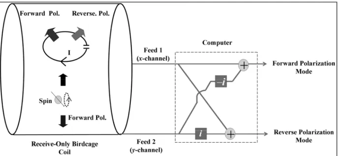
Figure 2.2: The receptively coupled RF (RCRF) coil and linear polarization. The MR signal induces
current on an RCRF coil and this creates a linearly polarized signal. A linearly polarized signal can be decomposed into forward and reverse polarized signals. Therefore, an RCRF coil functions as a polarization converter.
Figure 2.3: Visualizing the RCRF coil and the anatomy. Spins in the anatomy create a forward polarized signal. If an RCRF coil is placed in the RO birdcage coil, spin rotation induces current on the RCRF coil and it creates a linear polarized signal, which consists of both forward and reverse polarized signals. By feeding x and y-channels directly to the scanner, both forward and reverse polarization modes can be reconstructed.
Figure 2.4: Sketch of the upper end-ring part of the receive-only birdcage coil. The receive-only
birdcage coil has two feeds and an inductor-diode system is used for decoupling. Scanner-supplied DC current turns on the diode during RF transmission. Two back-to-back diodes are used for passive decoupling. Again, during the RF transmission, AC current on the end-ring turns on diodes which detune the coil, resulting in effective decoupling.
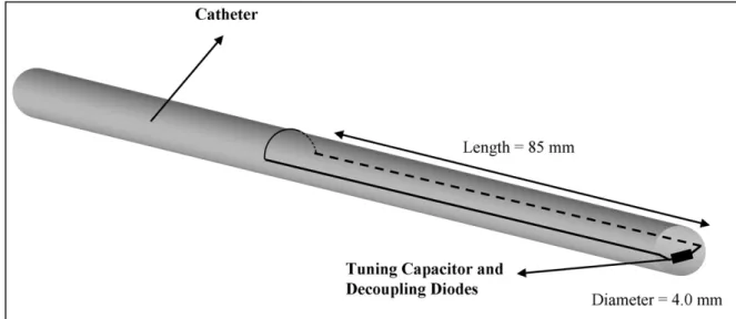
Figure 2.5: The RCRF coil. The RCRF coil has 4.0 mm in diameter and 85 mm long. It is constructed
from 0.4 mm diameter coated copper wire. The RCRF coil is tuned by a ceramic chip capacitor to 63.85 MHz using an HP 8753D network analyzer.
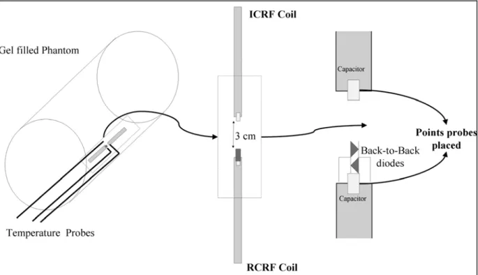
Figure 2.6: Sketch of the heating experiment involving ICRF and RCRF coils. Two coils were placed on the inner wall of the gel filled phantom. The phantom was leaned against the MR imager bore wall in order to obtain maximum heating. The coils were 3 cm from each other with the center of the MR
imager bore between them. Two probes were placed on the tips of the coils and another one was placed midway between the coils as a reference data probe. In the heating experiment we used fast SPGR with TR of 6.5 ms and flip angle of 90 o for duration of 690 seconds.
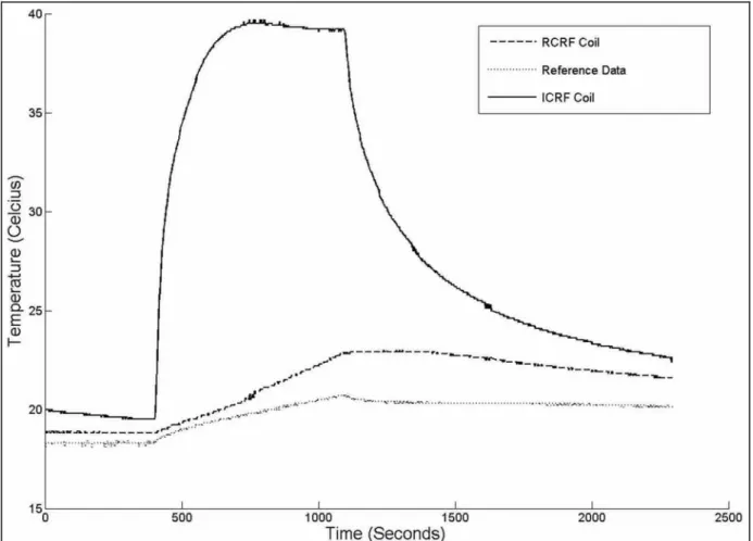
Figure 2.7:Plot of the heating experiment. A temperature rise of 2.4C was seen in 690 seconds in the
reference location. A sharp increase in temperature (15C in 100 seconds) at the tip of the ICRF coil was observed. This implies local heating around the tuning capacitor; the temperature increased by 20C over 320 seconds. However the RCRF coil heated much less (4.1C in 690 seconds).
Figure 2.8: Phantom imaging experiment. The forward polarization mode of images, the reverse polarization mode of images, and the color-coded images are in the left, the middle, and the right columns respectively. The first row shows images with a flip angle of 1o. Although a low flip angle was
used, the catheter appeared bright suggesting flip angle amplification. In this low flip-angle imaging case, the RCRF coil worked as an ICRF coil and a high contrast between the RCRF coil signal and the background signal was achieved.
As the flip angle was increased (second and third rows in Figure 2.8), the background signal intensity increased. No overtipping artifact (flip angles more than 90o) around the catheter was observed. This
suggested a successful decoupling by the back-to-back diodes. However, image contrast is significantly decreased.
Under all conditions, our algorithm worked successfully, as shown by the reverse polarization images (middle column in Figure 2.8). The background signal is almost completely suppressed in all cases. Color-coded images allowed visualization of the catheter and the background.
Figure 2.9: The animal imaging experiment with fast gradient echo sequence. As in the phantom
imaging experiment images, the forward polarization mode, the reverse polarization mode and the color-coded images are shown from left to right. Figures were acquired using slice thicknesses of 5 mm, 20 mm, and without slice selection.
In the first row (gradient echo images with slice thickness of 5 mm and flip angle of 1o), the catheter can be easily seen in the forward polarization mode image; background signal suppression was almost perfect in the reverse polarization mode image. On the other hand, with flip angle of 40o, the catheter
was barely visible in the forward polarization mode image, and background signal suppression was almost complete in the reverse polarization mode image. Color coding enabled visualization of both catheter and background.
As the slice thickness was increased (20 mm in Panel b, no slice selection in Panel c), visibility of the catheter decreased significantly in the forward polarization mode image even with a flip angle of 1o. Identification of the catheter was almost impossible in the forward polarization mode image when a flip angle of 40o was used. On the other hand, background suppression was effective in both reverse
polarization mode images. Again, the color-coding method enabled visualization of the catheter against the background.
Figure 2.10: The animal imaging experiment with SSFP sequence. SSFP sequence is frequently used in guidance of interventional procedures. As expected, visibility of the catheter in SSFP sequence was low in the forward polarization mode image; on the other hand, background suppression in the reverse polarization mode image was successful.
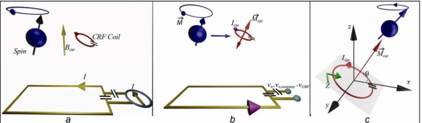
Figure 3.1:Sketch of the nth element of the phased array coil, CRF coil, and spin interactions. a) Bn
is the magnetic field generated by the nth element of the receive phased array coil at the point of interest
when the unit current, I, is applied to the terminals of the coil element. b) M is the rotating magnetization vector of spins and MCRF is the magnetization vector of the CRF coil that is oscillating in a linear trajectory. The spins around the CRF coil induce a current, ICRF. This current on the small CRF coil can be represented by a magnetization vector, MCRF. As a result of these magnetizations, a voltage, vn, is induced on the terminals of the external coil. c) Bc
is the magnetic field generated by the CRF coil at a point of interest when a unit current, I, is applied to an imaginary terminal of the coil.
is the orientation angle of the w.r.t x-axis of the CRF coil, and Z is the impedance at this imaginary terminal of the CRF coil.
Figure 3.2:The CRF coil design.
Figure 3.3: Sketch of the NaCl solution phantom and a volunteer for fiducial marker visualization.
Figure 3.4:Oblique images of the phantom. (a) The forward polarization mode of the image, (b) the reverse polarization mode of the image, and (c) the color-coded image. Although there is a KCl
solution-filled straw as a disturber, the reverse polarization method can separate the RCRF coil from the phantom.
Figure 3.5: Sagittal images of the phantom and ICRF coils. (a) The forward polarization mode of the image, (b) the reverse polarization mode of the image, and (c) the color-coded image. Although the phantom and contrast agent signals are stronger than the ICRF coil signal (left column), the reverse polarization method using the transmit array system suppresses all the signals other than the linearly polarized signal of the ICRF coil.
Figure 3.6: a) Oblique images of the phantom and ICRF coils. (a1) The forward polarization mode of
the image, (a2) the reverse polarization mode of the image, and (a3) the color-coded image. Similar to the previous case shown in Figure 3., the method successfully singles out the RCRF coil signal. However, because of the transmission decoupling, the RCRF signal is weaker than the ICRF coil signal. b) Transversal images of the ICRF coil, RCRF coil, and KCl solution. (b1) The forward polarization mode of the image, (b2) the reverse polarization mode of the image, and (b3) the color-coded image. Although the phantom and contrast agent signals are stronger than the ICRF coil signal (left column), the reverse polarization method using the transmit array system suppresses all signals other than the linearly polarized signal of the ICRF coil.
Figure 3.7:a) Oblique image of the receive array. (a1) The forward polarization mode of the image,
(a2) the reverse polarization mode of image, and (a3) the color-coded image.
b) Oblique image of the transmit array.(b1) The forward polarization mode of the image, (b2) the reverse polarization mode of the image, and (b3) the color-coded image. Similar to the receive array case, suppression of the anatomy signal for MR guidance is effective.
Figure 3.8:a) Transversal image of receive array coil. (a1) The forward polarization mode of the image (a2), the reverse polarization mode of the image, and (a3) the color-coded image.
b) Transversal image of transmit array. (b1) The forward polarization mode of the image, (b2) the reverse polarization mode of the image, and (c3) the color-coded image.
Figure 3.9:a) Sagittal image of receive array coil. (a1) The forward polarization mode of the image
(a2), the reverse polarization mode of the image, and (a3) the color-coded image.
b) Sagittal image of transmit array. (b1) The forward polarization mode of the image, (b2) the reverse polarization mode of the image, and (c3) the color-coded image.
Figure 4.1:A conventional MRI RF excitation and the field polarization using a single channel body
birdcage coil with a quadrature hybrid. The quadrature hybrid divides input excitation signal into two halves with 90o phase difference. This excitation enables a forward polarized field inside a birdcage coil.
Figure 4.2: Standard spoiled GRE sequence RF pulse schemes and the birdcage coil excitation using
the transmit array system. If the quadrature hybrid is eliminated and two excitation channels are input with a same spoiled GRE excitation pulses a linearly polarized field is created inside the birdcage coil.
Figure 4.3:The modified RF excitation scheme and the birdcage coil field using the transmit array
system. Excitations of the channels change such that a linearly polarized field with a turning polarization vector is created.
Figure 4.4: a) Interaction of the linear polarized RF and the ICRF coil. b) k-space lines result of circulating polarization vector.
Figure 4.5: Simulation results of TrueFISP sequence.
Figure 4.6: a) Phantom setup. The same phantom was used for imaging experiments. b) Result of the
rotational orientation experiment.
Figure 4.7: Transversal images of the method with varying number of turns, N. Images show that the amount of shifting pixel can be adjusted. a) Original image P1. b) P16. c) P8.
Figure 4.8: Color-coded images with changing parameters. a) Polarization vector turns counter-clockwise direction and phase encoding direction is A-P. b) Polarization vector turns counter-clockwise direction, same phase encoding direction with a. c) Polarization vector turns counter-clockwise direction and phase encoding direction is L-R.
Figure 4.9: Color-coded images of different planes. a) Coronal image. b) Sagittal image. c)
Figure 4.10: Imaging experiment results of TrueFISP sequence. a, b, and c shows transversal images
with different oil and KCl solutions. a) High oil signal intensity. b) High KCl solution intensity with suppressed oil signal. c) Highest KCl solution signal intensity with residual oil signal. d) Oblique plane with low oil signal intensity. e) Coronal plane with low background signal intensity.
Figure 5.1:Simulation of eight legs highpass inductively coupled birdcage coils. a) Forward mode of ICBC b) Reverse mode of ICBC.
Figure 5.2:A picture of the high-pass inductively coupled birdcage coil used in experiments.
Figure 5.3:A picture of the high-pass ICBC coil. Capacitors can be placed inside, outside, and on the endrings. Here, the capacitors are placed inside of the coil.
Figure 5.4:Tuning method of the coupled birdcage coils.
Figure 5.5: Window/Level are the same for all images. a) Axial image of mode 1 b) Sagittal image of
mode 1 c) Axial image of mode 2 d) Sagittal image of mode 2.
Figure 5.6: Window/Level are the same for all images. a) Axial image of mode 1 b) Sagittal image of
1. INTRODUCTION
Surgical procedures are performed for the direct visualization of possible diseases and for the treatment during the procedure. However, these procedures carry risks due to the direct exposure of the internal parts of human body. As an example, a by-pass operation needs an open surgery which may cause contamination. Interventional radiology is a profession that consists of minimally invasive procedures using radiological images. The purpose of the interventional radiology can be diagnostic and/or treatment with minimally invasive methods. Images are used to guide interventional devices such as biopsy needles, catheters, and guide-wires. Therefore, using minimally invasive interventional radiology methods minimizes infections and recovery times.
Precise and fast localization of the interventional devices is a necessity to perform minimally invasive operations. In order to acquire images for guidance, different modalities are used in interventional radiology. Ultrasound is inexpensive but suffers from poor contrast. Today, catheter based X-ray procedures are commonly used with high success rates for the treatment of wide range of illnesses. Although X-ray provides almost perfect visualization of the interventional devices, the soft tissue contrast is very poor and only very skilled operators can perform these procedures successfully [1]. Furthermore, not only patients, but also staffs are exposed to high dose of ionizing radiation which may cause long term health problems. As compared to other imaging techniques, MRI is a non-ionizing modality and a very promising option for the accurate guidance of the complicated interventional procedures providing high soft tissue contrast. However, visualizing the interventional devices using MRI is rather difficult as opposed to X-ray. Therefore many tracking techniques have been developed. Paramagnetic materials [1-3], contrast agents [4-6], and other local signal manipulators [7, 8] are the main passive tracking tools. Automatic identification of the position of the catheter in passive tracking techniques [9] is difficult, because, these approaches typically yield weak contrast. Alternatively, it is also possible to obtain an image of both the catheter and the background simultaneously with active techniques [10, 11] which also address the contrast issue [12-20]. However, in that case, the catheter needs to be electrically connected to the MR scanner and this may cause radio frequency (RF) safety problems as well as difficulties in handling the device. There are also hybrid methods which make use of an inductively coupled RF (ICRF) coil [21]. ICRF coils [22] are simple wire loops made resonant using a capacitor. A
transmit field induces current on the ICRF coil that amplifies the excitation field in its vicinity and creates MRI signal amplification. These coils have been used for small field of view (FOV) imaging [23, 24] as well as catheter tracking [21, 25]. In our studies, we aimed to improve the interventional device visibility using the ICRF coils and reverse polarization method.
The reverse polarization method is related to precession direction of spins under a DC magnetic field. Spins are fundamental characteristic property of particles and when they are exposed to a torque under a DC magnetic field they precess and this precession causes magnetization and angular momentum. Direction of the precession is dependent on the direction of the DC magnetic field with the left hand rule. In MRI, DC magnetic field is Bo and
its direction is on the z-axis. We call the precession of spins in MR scanner as forward polarization. Spins can be excited by a forward polarized field and a coil, which is sensitive to forward polarized field, can receive signal due to spin precession. Coils are MR hardware components that transmit magnetic field to excite spins and/or receive magnetic field created by spins in human body. On the other hand, a reverse polarized excitation cannot excite spins and also a coil with reverse polarized sensitivity cannot receive signal of the spins.
The first three studies in this dissertation are mainly related to catheter tracking. The reverse polarization method is introduced in the second chapter. Its implementation to transmit and phased array coils are explained in the third chapter. Circulating linear polarization vector using transmit array system will be discussed in the forth chapter. A novel inductively coupled birdcage coil design is the subject of the fifth chapter.
In the second chapter of the thesis, an ICRF coil visualization method, which allows separation of the catheter and the anatomical information by using the reverse and forward polarization modes of a receive-only birdcage coil, is proposed. Birdcage coils are very common cylindrical shaped volume coils that is used to image subject inside the coil. The reverse polarization method allows images of the anatomy and the catheter to be combined into a color-coded image where color-coding is used to monitor the catheter signal during interventions. Quadrature hybrids are passive devices that are used in birdcage coils in order to obtain forward polarized magnetic field excitation and reception. In our method, a receive-only birdcage coil without a quadrature hybrid was constructed and then it was connected to a
scanner as a two-channel phased array receive coil in order to reconstruct both forward and reverse polarized images simultaneously. MR signals acquired from the two channels were added after phase adjustments to create the reverse and forward polarization modes images. The reverse polarization mode image contained signal only from the ICRF coil, but the forward polarization mode displayed both the anatomical information and the ICRF coil.
In all of the MRI applications and methods explained above, a conventional imaging system has been used. In these systems, there is a single channel RF transmit birdcage body coil that produces forward polarized rotational field. This field is used to flip spins in the anatomy. The signal originates from the anatomy due to the transmit coil excitation and it is received by different RF coil types. A body coil is a single channel transmit coil, but at the same time it can be used as a single channel receive coil. On the other hand phased array coils are multi-channel RF receive coils and weights can be optimized to increase signal-to-noise ratio (SNR). Transmit array systems have recently been introduced for experimental studies. These systems enable multi-channel RF transmission. Similar to the multi-channel reception case, such a system can be optimized for higher SNR. However, transmit array studies are mostly concentrated on understanding the working principles, exploring the capabilities of the system, and homogenizing B1 fields at high frequencies. Therefore, usage of the transmit array system
has been limited. In our second study, we attempt to improve the visibility of the interventional devices by implementing the reverse polarization method to not only phased array but also transmit array coils. Two different applications of the reverse polarization method are presented in this part: a) catheter tracking and (b) fiducial marker visualization, in both of which transmit and receive arrays are used.
Our third study in the forth chapter proposes a novel method for i) the detection of rotational orientation, and ii) the position tracking of an ICRF coil using a transmit array system. The method can be used with an interventional device (such as catheters and guidewires) on which an ICRC coil is constructed. In this study, a conventional body birdcage coil is used, but the quadrature hybrid is eliminated for a two channel transmission similar to the first and the second studies. This study may look very similar to the reverse polarization method mentioned above, but in this method, conventional sequences were modified and excitation scheme was changed during the acquisition. Furthermore, the transmit array system provided two identical RF pulses with different phase and amplitude at each repetition time (TR) in order to obtain
linearly polarized excitations instead of conventional forward polarized rotational excitation. Responses of the anatomy and the ICRF coil to this RF excitation scheme are different such that they can be separated in real-time. After separating the devices from the anatomy signal, a color-coded image is reconstructed. More importantly, this novel method enables to calculate the absolute orientation of the ICRF coil constructed on a catheter in real-time without any extra cost. Even though many researchers tried to deal with the tracking problem, only Anderson et al. tried to address a solution for the rotational orientation issue using phase images of active micro coils manually [26]. The rotational orientation information may increase the control on the catheter and can be extremely useful for several applications, such as MR-guided intravascular focused ultrasound (IVUS) [27, 28] with independent transducer arrays [29] and RF ablation. FLASH (Fast Low Angle SHot Magnetic Resonance Imaging) [66] and TrueFISP (True fast imaging with steady state precession) [67] are two different fast sequences commonly used in real-time applications. An MR sequence is a set of RF and gradient magnetic pulses and time spacing between these pulses. Sequences are used in conjunction with gradient fields and MR signal reception to produce MR images. Modified FLASH and TrueFISP sequences are used for tracking experiments. Nevertheless, only the FLASH sequence is used to detect rotational orientation of the catheter. The acquired images using the method we present show the feasibility of the different applications, such as the catheter-tracking. Furthermore, rotational orientation information of the catheter is important in some of the applications, such as MR guided endoluminal focused ultrasound, RF ablation, side looking optical imaging, and asymmetric needle puncturing. The method we introduced in this chapter makes these applications feasible.
In the applications explained above, the birdcage coil has been mentioned and used as a volume coil, i.e. subjects are placed inside the coil, because, the field of an inner volume of a birdcage coil is very homogeneous. However, using outside of the birdcage coil has not been considered by researchers because of its size and shape (Figure 2.1). In the fifth chapter, a new miniaturized birdcage coil design without any matching and active decoupling circuits, amplifiers, and wire connectors, is introduced. Similar to the inductively coupled RF coils, the standalone birdcage coil design couples to the external coils inductively. The main advantage of the standalone design is being independent from scanner manufactures. The new design can be used as an internal imaging coil and catheter tracking.
MRI is a very promising modality for minimally invasive interventional procedures. In this dissertation, solutions and improvements for interventional MRI using reverse polarization are presented. The reverse polarization concept was introduced in order to make use of “useless” component of MRI signal in 2006 [30]. We believe this study will pave a way for better imaging systems for more accurate diagnostics and treatments using the reverse polarization idea.
2. A CATHETER TRACKING METHOD
USING REVERSE POLARIZATION FOR
MR-GUIDED INTERVENTIONS
.
2.1. Introduction
Magnetic Resonance Imaging (MRI) is a very promising option for accurate guidance of complicated interventional procedures as it provides high soft tissue contrast; however visualizing interventional devices is rather difficult and many tracking techniques have been developed. Automatic identification of the position of the catheter in passive tracking techniques [9] is difficult. But with active techniques [10, 11], it is possible to obtain an image of both catheter and background simultaneously. However, the catheter needs to be electrically connected to the scanner and this may cause RF safety problems and difficulties in handling the device.
In 2005, Quick et. al. proposed wireless active catheter visualization [21] by using an ICRF coil [31]; this can be classified as a hybrid method blending active and passive catheter visualization techniques. A sequence with a small flip angle (<5o) is used to visualize the catheter. The amplified flip angle generates a bright signal around the catheter against a low intensity background image. However, when a sequence with a strong background signal is used, it may be difficult to locate the catheter, and the high flip angles around the catheter become a safety concern. While the safety problems may be eliminated using decoupling techniques during RF transmission, the flip angle amplification property of the transmit mode will be lost, leaving only the signal amplification in the receive mode which renders visualization of the ICRF coil difficult [32]. In active tracking techniques, this problem has been solved by separate acquisition of the catheter and background signals and by color-coding the images [33, 34].
In this study, a novel technique for catheter tracking using an ICRF coil that allows the separate acquisition of background and catheter images simultaneously is proposed. This
method allows real-time, color-coded display of the ICRF coil on a background image. An in-vivo animal experiment demonstrates the feasibility of the proposed method.
2.2. Theory
In MRI, excited spins generate a rotating magnetic field which can be picked up by a quadrature coil tuned to receive a forward polarized magnetic field. When such a coil is physically reversed or tuned to the reverse polarized magnetic field, no signal can be detected. On the other hand, if the magnetic field is generated by a current on a simple loop instead of excited spins, the field does not rotate; instead it oscillates generating a linearly polarized field. This field can be picked up by quadrature coils tuned either to forward or reverse polarized magnetic fields, because a linearly polarized field can be decomposed into forward and reverse polarized magnetic fields. When a resonating loop is placed on a catheter, excited spins induce current on this loop and its associated magnetic field can be picked up by a quadrature coil tuned to the reverse polarization field.
Note that the same coil cannot detect any signal directly coming from the excited spins. This section outlines the theory behind this phenomenon.
2.2.1. Birdcage Volume Coil
Birdcage [35] coils have been widely used since they were first introduced in 1985 by Hayes et. al. They have two main advantages: first, they create homogenous magnetic fields; second, they can easily be built as a quadrature coil.
With a quadrature hybrid circuit, standard quadrature birdcage coils are sensitive to the forward polarized magnetic fields (Figure 2.1a).
This can be explained by the principle of reciprocity: when a unit current is applied to one of the two feeds of the birdcage coil, a uniform magnetic field in x-direction is generated, suggesting that the signal received from this feed is the x-component of the magnetic field. Similarly, when the other feed is used to receive the MRI signal, it becomes sensitive to the y-component of the magnetic field.
If the signal received from feed-2 (y-channel) is
/
2
phase-delayed before adding to the other, the coil becomes sensitive to the forward component of the magnetic field. This phase delay can be represented by multiplying by the complex number . iFigure 2.1: a) Standard birdcage coil configuration. The birdcage coil has two feeds and they are connected to a quadrature hybrid. The quadrature hybrid creates a 90o phase difference between the x
and y components of the received signals which are added to obtain the forward polarization mode signal. b) Reverse polarization mode image of a standard birdcage coil. In a perfect system, no MRI signal can be detected, if the phase of the MRI signal from feed 2 (y-channel) is advanced by 90o before
adding. The same effect can be obtained by cross connecting the feeds to the quadrature hybrid connections. However, imperfect systems may result in some signals as seen in the figure. (This figure was taken from [25])
On the other hand, if the feeds of the birdcage coil are connected in reverse order, the signal received from feed-2 (y-channel) is
/
2
phase-advanced before adding to the other; this time, the coil becomes sensitive to the reverse component of the magnetic field. This phase delay can be represented by multiplying by the complex number . Ideally, the resultant image should i consist of noise only. However, imperfections in the birdcage coil and quadrature hybrid designs mean that we receive some signals (Figure 2.1b), but the reconstructed image is very noisy.2.2.2. Soft Quadrature Hybrid
The phase manipulations described above can also be done using software. If image raw data is multiplied by a constant, for example i or
e
i/2, the magnitude of the pixel value will remain unchanged but its phase will advance by
/
2
. The addition operation is also very straightforward for a computer program.If the signals from feeds 1 and 2 are directly acquired, the function of the quadrature hybrid can be imitated by a simple computer program. Thus with a soft-quadrature-hybrid, two images representing forward and reverse polarization modes can be obtained simultaneously. These operations can be completed very rapidly making real-time implementation possible.
Figure 2.2: The ICRF coil and linear polarization. The MR signal induces current on an ICRF coil and
this creates a linearly polarized signal. A linearly polarized signal can be decomposed into forward and reverse polarized signals. Therefore, an ICRF coil functions as a polarization converter. (This figure was taken from [25])
Figure 2.3: Visualizing the ICRF coil and the anatomy. Spins in the anatomy create a forward polarized signal. If an ICRF coil is placed in the RO birdcage coil, spin rotation induces current on the ICRF coil and it creates a linear polarized signal, which consists of both forward and reverse polarized signals. By feeding x and y-channels directly to the scanner, both forward and reverse polarization modes can be reconstructed. (This figure was taken from [25])
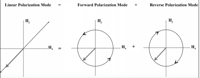
2.2.3. Linear Polarization
Spins produce a forward polarized field in the receive-only birdcage coil; therefore in reverse polarization mode, no signal can be detected.
On the other hand, if the magnetic field is generated by a current on a simple loop instead of excited spins, the field oscillates rather than rotating. This linearly-polarized magnetic field can be decomposed into forward and reverse polarized fields and therefore can be detected in both forward and reverse polarization modes (Figure 2.2).
When an ICRF coil is placed inside the birdcage coil, spin rotation induces current on the ICRF coil. This current produces a linearly polarized field allowing us to obtain the ICRF coil image in reverse polarization mode without any signal coming directly from the anatomy (Figure 2.3).
2.4. Method
2.4.1. Receive-Only Birdcage Coil
A conventional high-pass receive-only birdcage coil with 12 legs was built. Diodes were used for decoupling (Figure 2.4)
Figure 2.4: Sketch of the upper end-ring part of the receive-only birdcage coil. The receive-only birdcage coil has two feeds and an inductor-diode system is used for decoupling. Scanner-supplied DC current turns on the diode during RF transmission. Two back-to-back diodes are used for passive decoupling. Again, during the RF transmission, AC current on the end-ring turns on diodes which detune the coil, resulting in effective decoupling. (This figure was taken from [25])
In our design, two feeds of the coil were not connected to the quadrature hybrid. A soft-quadrature hybrid system was used instead and the two feeds were directly connected to the dual phased array connector of a 1.5 tesla MR scanner [36 Wisconsin, USA #242]. The acquired data was reconstructed in forward and reverse polarization modes (as described in the Theory section) using a MATLAB code.
2.4.2. Inductively Coupled RF Coil
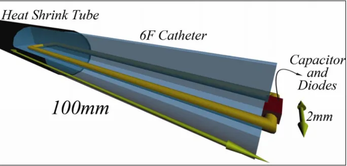
Two types of ICRF coils were built. The first one did not contain any diodes and therefore it coupled with both RF transmit and receive coils. The coil was 8.5-cm long and constructed on a 2 mm Teflon catheter using coated copper wire 0.4 mm in diameter; a heat shrink tube was used for isolation resulting in a prototype device with an outer diameter of 4 mm (Figure 2.5). It was tuned by a 75 pF ceramic chip capacitor [37] to 63.85 MHz using an HP 8753D network analyzer [38 CA, USA #244]. This design was used only in heating experiments.
The second type of ICRF coil was the same except for a pair of back-to-back BAS70INCT-ND schottky diodes [39] in parallel to the 75 pF tuning capacitor. We call this a receptively coupled RF (RCRF) coil because it couples with the RF receive coils rather than with the transmit coil. The RCRF coil was used in heating experiments as well as in all imaging experiments.
There were two performance criteria in our ICRF coil study: visibility and safety of the coils during any interventional procedure. Quick et.al reported that the contrast-to-noise ratio performance obtained using the ICRF coil is higher than the performance obtained using the RCRF coil [32]. However, the RF safety profiles of these coils have not been investigated. Therefore, we tested the RF safety performance of the two coils.
2.4.3. Phantom Heat Experiments
In the safety test, we measured the safety index, i.e. maximum temperature rise for a given specific absorption rate (SAR) as described in [40]. Since the relation between temperature and SAR is approximately linear, this measure gives a result that is independent of test condition.
In order to reduce measurement errors introduced by the temperature measurement device (±0.2C) we chose to maximize the applied SAR. In the phantom heat experiments, a gel filled bottle was used (Figure 2.6).
Both ICRF and RCRF coils were placed on the inner wall of a 5lt bottle that had a diameter of 21 cm. The bottle was leaned against the bore of the MR scanner.
Figure 2.5: The RCRF coil. The RCRF coil has 4.0 mm in diameter and 85 mm long. It is constructed
from 0.4 mm diameter coated copper wire. The RCRF coil is tuned by a ceramic chip capacitor to 63.85 MHz using an HP 8753D network analyzer. (This figure was taken from [25])
The heating experiment used fast spoiled gradient echo (SPGR) using the following imaging protocol: echo time (TE): 0.9 ms, repetition time (TR): 6.5 ms, flip angle: 90o, slice thickness:
20 mm, spacing: 0 mm, matrix: 256 X 128, FOV: 480 X 480 mm2, 15 phases per location, number of excitation (NEX): 60, bandwidth (BW): 62.50 Hz, acquisition duration: 690 seconds.
Neoptix ReFlex 4 channel signal conditioner and T1 fiber optic temperature sensors were used to measure temperature [41 Quebec City, Canada #246]. Since we expected the highest electric field around the capacitor, sensor tips touched the regions where the capacitors were placed. Another sensor was placed on the inner wall of the bottle away from the coils to measure applied maximum SAR (Figure 2.6). At 18.7C, thermal conductivity, specific heat capacity, and thermal diffusivity of the gel were measured by a KD2Pro thermal properties analyzer [42 USA #247] by simply inserting the needles of the analyzer into the phantom. A sample of the gel is taken from the phantom that had a measured density of 1150 kg/m3.
As it will be explained in Results section, the RCRF coil was shown to be safer to use and therefore the imaging experiments was conducted using only this type of coil.
Figure 2.6: Sketch of the heating experiment involving ICRF and RCRF coils. Two coils were placed on the inner wall of the gel filled phantom. The phantom was leaned against the MR imager bore wall in order to obtain maximum heating. The coils were 3 cm from each other with the center of the MR imager bore between them. Two probes were placed on the tips of the coils and another one was placed midway between the coils as a reference data probe. In the heating experiment we used fast SPGR with TR of 6.5 ms and flip angle of 90o for duration of 690 seconds. (This figure was taken from [25])
2.4.4. Phantom Imaging Experiments
Phantom imaging experiments were conducted to study the reverse polarization technique in ideal conditions. In these experiments, the RCRF coil was inserted into a gel filled bottle. Sagittal images were taken using a gradient echo sequence with several flip angles (1o, 5o, and
40o). The following gradient echo parameters were used: TR/TE: 40/3.4 ms; spacing: 1 mm;
slice thickness: 20 mm; matrix: 256 X 256; FOV: 300 X 300 mm2.
2.4.5. Animal Imaging Experiments
Proof-of-principle animal experiments were done using the RCRF coil. The rabbit esophagus was chosen for ease of implementation [43] and also to test the design in one of the most challenging anatomical structures. Esophagus lies next to trachea, aorta, great veins, lungs and heart. In addition, air inside esophagus makes it difficult to visualize using MRI. The experiments conformed to the Guidelines for the Care and Use of Laboratory Animals, and were approved by the Gazi University ethics committee, Ankara, Turkey. Two New Zealand and two Angora rabbits were used. General anesthesia was induced by intramuscular injection
of 5 mg/kg of ketamine and 40 mg/kg of xylazine. Then the RCRF coil was lubricated and inserted via the mouth into the duodenum. The rabbit was then placed on an MR table and images were taken while the catheter with the RCRF coil was withdrawn through the esophagus. The motion of the tube inside the esophagus was recorded by fast gradient echo and steady state free precession (SSFP) imaging sequences.
The fast gradient echo parameters were: TR/TE: 7/1.9 ms; matrix: 256 X 256; FOV: 300 X 300 mm2; acquisition time: 1.8 seconds. The SSFP parameters were: TR/TE: 6.3/1.7 ms; matrix: 256 X 256; FOV: 300 X 300 mm2; flip angle: 40o; slice thickness: 20 mm; acquisition time: 1.6
seconds.
2.5. Results
2.5.1. Phantom Heat Experiments
At 18.7C, the thermal properties of the gel in the phantom were: thermal conductivity,
0.51 W/mK
K ; specific heat capacity, C3820 KJ/m3K; thermal diffusivity, 3
0.13 mm /sec
D . The density of the gel was 1150 kg/m3 and hence heat capacity was 4400
J/kg K. Both coils that are described in the Method section were used in phantom heat experiments. A temperature rise of 2.4C was observed in 690 seconds (Figure 2.7) in the reference location suggesting that the applied SAR was 15 W/kg. Note that the SAR value estimated by the scanner is known to be unreliable [44] when phantoms are used; therefore we used this measured SAR as the applied SAR.
A sharp increase in temperature (15C in 100 seconds) was observed at the tip of the ICRF coil (Figure 2.7). This implies local heating around the tuning capacitor. The temperature increased by 20C over 320 seconds. The safety index [40] is calculated to be 1.3C /(W/kg) In other words, 1.5 W/kg peak power is the maximum that can safely be applied. This will produce a maximum temperature of 2C while the device is in the body. The temperature of the RCRF coil however increased much less (4.1C in 690 seconds). The temperature rise was linear in time, and therefore this heating was not local. This suggests that the RCRF coil is much safer to use. Detailed analysis is necessary to determine under what conditions this coil can be scanned safely. As a result of this experiment, we chose to conduct the rest of the experiments using the RCRF coil
Figure 2.7:Plot of the heating experiment. A temperature rise of 2.4C was seen in 690 seconds in the
reference location. A sharp increase in temperature (15C in 100 seconds) at the tip of the ICRF coil was observed. This implies local heating around the tuning capacitor; the temperature increased by 20C over 320 seconds. However the RCRF coil heated much less (4.1C in 690 seconds).(This figure was taken from [25])
2.5.2. Phantom Imaging Experiments
Figure 2.8 shows the results of the phantom imaging experiments; the forward polarization mode images are in the left column, reverse polarization mode images are in the center, and color-coded images are in the right column. The first row shows images with a 1oflip angle.
Although a low flip angle was used, the catheter appeared bright suggesting flip angle amplification. This can be explained by the fact that when a low flip angle is used, induced voltage across the back-to-back decoupling diodes may be lower than their turn-on voltage (0.3 volts for the Schottky diodes). In this low flip-angle imaging case, the RCRF coil worked as an ICRF coil so that high contrast was achieved between the RCRF coil signal and the background signal. As the flip angle was increased (second and third rows in Figure 2.8), background signal intensity increased. No overtipping artifact (flip angles more than 90o) was
observed around the catheter, which means a successful decoupling by the back-to-back diodes was accomplished; however, image contrast was decreased significantly.
In all conditions, our algorithm worked successfully as can be seen in the reverse polarization images (middle column in Figure 2.8). The background signal is almost completely suppressed in all cases. The color-coded images enabled visualization of the catheter and the background.
Figure 2.8: Phantom imaging experiment. The forward polarization mode of images, the reverse polarization mode of images, and the color-coded images are in the left, the middle, and the right columns respectively. The first row shows
images with a flip angle of 1o.
Although a low flip angle was used, the catheter appeared bright suggesting flip angle amplification. In this low flip-angle imaging case, the RCRF coil worked as an ICRF coil and a high contrast between the RCRF coil signal and the background signal was achieved.
As the flip angle was increased (second and third rows in Figure 2.8), the background signal intensity increased. No overtipping artifact (flip angles more than 90o) around the catheter was observed. This suggested a successful decoupling by the back-to-back diodes. However, image contrast is significantly decreased.
Under all conditions, our algorithm worked successfully, as shown by the reverse polarization images (middle column in Figure 2.8). The background signal is almost completely suppressed in all cases. Color-coded images allowed visualization of the catheter and the background. (This figure was taken from [25])
2.5.3. Animal Imaging Experiment
The phantom has a uniform structure; therefore, the RCRF coil can be separated from the phantom easily. However, this is not the case in animal experiments because of the complex structure of tissues. As slice thickness and flip angle increase, visualizing the catheter becomes harder with standard imaging techniques.
Figure 2.9 shows the results of the rabbit experiments. As in the images from the phantom imaging experiment, the forward polarization mode of images, the reverse polarization mode of images and color-coded images are shown from left to right. Figures 2.9a-c are fast gradient echo images, acquired using slice thicknesses of 5 mm, 20 mm, and without slice selection. In addition, SSFP sequence images are shown in Figure 2.9d; these are frequently used to guide interventional procedures. In the first row (gradient echo images with a slice thickness of 5 mm and a flip angle of 1o), the catheter can be easily seen in the forward polarization mode image;
in the reverse polarization mode image, background signal suppression was almost perfect. But with a flip angle of 40o, the catheter was barely visible in the forward polarization mode image,
and the background signal suppression was almost complete in the reverse polarization mode image. Color-coding enabled visualization of the catheter against the background.
As slice thickness was increased (20 mm in Figure 2.9b, no slice selection in Figure 2.9c), visibility of the catheter decreased significantly in the forward polarization mode image even with a flip angle of 1o. Identification of the catheter was almost impossible in the forward
polarization mode image when a flip angle of 40o was used. On the other hand, background
suppression was effective in both reverse polarization mode images. Again, color-coding enabled visualization of the catheter within the background. As expected, visibility of the catheter in the SSFP sequence was low in the forward polarization mode image, but background suppression in the reverse polarization mode image was successful (Figure 2.9d).
Figure 2.9: The animal imaging experiment with fast gradient echo sequence. As in the phantom imaging experiment images, the forward polarization mode, the reverse polarization mode and the color-coded images are shown from left to right. Figures were acquired using slice thicknesses of 5 mm, 20 mm, and without slice selection.
In the first row (gradient echo images with slice thickness of 5 mm and flip angle of 1o), the catheter
can be easily seen in the forward polarization mode image; background signal suppression was almost perfect in the reverse polarization mode image. On the other hand, with flip angle of 40o, the catheter
was barely visible in the forward polarization mode image, and background signal suppression was almost complete in the reverse polarization mode image. Color coding enabled visualization of both catheter and background.
As the slice thickness was increased (20 mm in Panel b, no slice selection in Panel c), visibility of the catheter decreased significantly in the forward polarization mode image even with a flip angle of 1o. Identification of the catheter was almost impossible in the forward polarization mode image when a flip
angle of 40o was used. On the other hand,
background suppression was effective in both reverse polarization mode images. Again, the color-coding method enabled visualization of the catheter against the background. (This figure was taken from [25])
Figure 2.10: The animal imaging experiment with SSFP sequence. SSFP sequence is frequently used in guidance of interventional procedures. As expected, visibility of the catheter in SSFP sequence was low in the forward polarization mode image; on the other hand, background suppression in the reverse polarization mode image was successful. (This figure was taken from [25])
2.6. Discussion
A modified birdcage coil was manufactured in order to demonstrate the principles of the reverse polarization method. Our algorithm is very suitable for real-time implementation because it requires only one multiplication and one summation. Color-coding was already implemented in real-time [34].
The new method has not been implemented in a real-time imaging system. This will be essential if this method is to be useful in guiding interventional procedures. The processing power necessary to obtain reverse and forward polarization mode signals is minimal.
Our method can be used not only in catheter-tracking procedures but also possibly in tracking other interventional devices. For example, tracking coils [15] may be replaced by RCRF coils. This will eliminate the need for electrical connections between the interventional devices and scanner receivers [45], but needs further investigations.
In this study only phantom heat experiments were conducted. The exact conditions in which ICRF and RCRF coils can be used in MRI scanners needs to be investigated using detailed analysis backed by animal experiments and possibly with clinical tests. However, our results suggest that the heating around RCRF coils is significantly less than ICRF coils.
Currently, the use of implantable RF coils for high-resolution imaging of deep organs is under investigation [23]. One problem with the high-resolution imaging technique with implantable
coils is image overlaps. When a small field-of-view is used for high-resolution imaging, the large external coil receives signal from out of region of interest. This unwanted signal occasionally causes image overlaps. If a reverse polarization mode signal is used, the signal directly picked up by these coils can be eliminated and high-resolution imaging without image overlap may be possible.
This study started during my masters program and mentioned also in my Master’s Thesis. However, most of the work was completed during my PhD program. Mainly, comparison of the ICRF and RCRF coils, phantom heating experiments, usage of the RCRF coil, all other imaging experiments were done after the completion of the MSc program.
2.7. Conclusion
The feasibility of background suppression using a reverse polarization mode signal in catheter tracking using inductively coupled RF coils was demonstrated. With a single birdcage coil, both reverse and forward polarization mode signals were obtained. Imaging of the target object with a real-time imaging sequence using the forward polarization mode signal was possible and the catheter was distinctly seen in the reverse polarization mode signal. Color-coding enabled simultaneous visualization of catheter and the anatomy without any restriction on the pulse sequence. The effectiveness of this method was tested by phantom and animal experiments. Clinical studies are needed to demonstrate the role of this technique in medicine.
3. REVERSE POLARIZED INDUCTIVE
COUPLING TO TRANSMIT AND
RECEIVE RF COIL ARRAYS
3.1. Introduction
In the previous chapter, the reverse polarization method for catheter tracking using a birdcage coil is introduced [25]. This method separates anatomical information from an RCRF. Although this method can be an excellent candidate for making the interventional devices visible, its main drawback is the requirement of a birdcage volume coil as the receiver. In today’s practice birdcage coils are seldom used as receive coils because of their lower performance compared to the phased array coils [46]. Notably, it is known that individual simple elements of a phased array coil create a linearly polarized magnetic field [47], therefore it is not a trivial task to generate reverse polarized sensitivity using the phased array coils.
Here, a method is presented for obtaining reverse polarized sensitivity using a phased array coil system. It is also shown that by using duality, the proposed method can be employed to obtain reverse polarization through radio-frequency transmit-array systems.
“Wireless” active catheter tracking [32] and fiducial marker visualization [48-52] are demonstrated as applications of the proposed method. In both of these applications, induced radio-frequency current flows on a coupled RF (CRF) coil, amplifies the rotating magnetization vector, and finally turns into an oscillating magnetization in a linear path. This magnetization can be decomposed into rotating magnetization vectors, one travelling in the forward direction and the other in reverse. Since an anatomical signal can only be generated by the forward polarized magnetization vector, an image that is sensitive to the reverse polarized magnetization will solely contain the signal received by the CRF coil.
3.2. Theory
The reverse polarization method can be implemented using the receive and/or transmit paths.
3.2.1. Reverse Polarization Method Using Receive (Phased) Array RF Coils
As explained in the previous chapter, implementing the reverse polarization method to a receive coil with uniform sensitivity, such as the birdcage coil, is trivial because: i) both feeds of the birdcage coil have the same sensitivity magnitude, and ii) the phase difference between the feeds is same for all pixels. As a result, shifting the phase of the y-channel by -90o or 90o and summing with the x-channel produce forward or reverse polarized modes of the images [25, 53]. However, phased array coils do not have uniform sensitivity profiles and thus to obtain the reverse polarized mode of an image, a more sophisticated algorithm is necessary. In this section, the anatomy and CRF coil signals received by a linear phased array coil will be derived. In addition, the algorithm of the reverse polarization method for the receive array coils, which consist of linear coils, will be presented.
If the direction of the main magnetic field is reversed, a quadrature receive-only birdcage coil can not receive any MRI signal. On the other hand, if a linear coil, such as a simple loop coil, is used to receive the signal, the direction of the magnetic field is not important. In either case, the linear coil picks up the signal with equal sensitivity. When multiple linear coil elements are used as a phased array coil, their signals originating from the same point of interest can be combined to produce pure forward and reverse sensitivities. In the MR literature, the rotation direction of a magnetic field is usually explained in the rotating frame. Since both forward and reverse polarizations will be utilized in this study, it is difficult to explain this concept in the rotating frame. Therefore, in this text, magnetic fields will be expressed using the phasor notation with the ei t0 convention, where “i” is the imaginary unit number ( ) and 1
0
is the Larmor frequency.
Assume that a phased array coil with N linear coil elements is used to image an anatomy with a CRF coil placed inside it. The phased array coil elements receive two types of signals from a point of interest close to the CRF coil: a direct signal of the spins and an indirect signal of the CRF coil. Rotating spins induce a current on the CRF coil and this current creates a linear
magnetic field that has both forward and reverse polarized components. The signal of the spins and then the signal of the CRF coil will be derived.
3.2.1.1. The anatomy Signal
Let vn anatomy, be the open circuit voltage of the nth element of an N-channel phased array coil caused by the spins at the point of interest. In order to find the total voltage, this quantity needs to be integrated over the whole volume. However, by itself, this value is directly related to the sensitivity of the coil element at this point of interest. The voltage can be formulated using the reciprocity principle [54-56]:
,
n anatomy o n
v i M B , (3.1)
where “ ”, represents the dot product and M is the phasor representation of the rotating magnetization vector given by:
x y
M m a ia (3.2)
where m is the complex representation of the transverse magnetization and, ax and ay are unit vectors in x and y directions, respectively.
Note that Eq.(3.2) is the phasor equivalent of the time domain representation of the magnetization M t
m cos
0t m a
x m sin
0t m a
y. In Eq.(3.1), Bn
is the
magnetic field at the point of interest generated by the nth element of the receive phased array coil when a unit current is applied to the terminals of the coil element (Figure 3.1a). Note that
n
B is a linearly polarized magnetic field and all the elements of the phased array coil have the same phase at a point of interest since this value is carefully calibrated in the MRI scanner. In this study, the z-component of the magnetic field is ignored since it has no contribution to this analysis.
3.2.1.2 CRF Coil Signal
The CRF coil is the secondary source of the magnetic field, i.e. the spins around the CRF coil induce the current, ICRF, on the CRF coil. This current on the small CRF coil can be represented by a magnetization oscillating on a linear trajectory (Figure 3.1b).
Note that a linearly polarized magnetization can be decomposed into two counter-rotating magnetizations, i.e. the forward and reverse polarized magnetizations. The linearly polarized external receive coils are sensitive to both components of the linearly polarized magnetization.
Similar to the anatomy case in Eq.(3.1), the voltage induced on the nth coil by the CRF coil can
be expressed using the magnetization vector of the CRF coil,MCRF, as (Figure 3.1b):
,
n CRF o CRF n
v i M B . (3.3)
Note that the magnetic field, Bn
, is assumed to be the same magnetic field as in Eq.(3.1), because the CRF coil is small and the point of interest is very close to it. The magnetization of the CRF coil originates from the current and is proportional to its unit surface area, s, and the normal vector:
cos sin 2 CRF CRF x y i i CRF x y x y M I s a a I s e a ia e a ia (3.4)Above, is the orientation angle of the CRF coil with respect to the x-axis.
Figure 3.1:Sketch of the nth element of the phased array coil, CRF coil, and spin interactions. a)
n
B
is the magnetic field generated by the nth element of the receive phased array coil at the point of interest
when the unit current, I, is applied to the terminals of the coil element. b) M is the rotating magnetization vector of spins and MCRF is the magnetization vector of the CRF coil that is oscillating in a linear trajectory. The spins around the CRF coil induce a current, ICRF. This current on the small CRF coil can be represented by a magnetization vector, MCRF. As a result of these magnetizations, a voltage,
n
v , is induced on the terminals of the external coil. c) Bc
is the magnetic field generated by the CRF coil at a point of interest when a unit current, I, is applied to an imaginary terminal of the coil. is the orientation angle of the w.r.t x-axis of the CRF coil, and Z is the impedance at this imaginary terminal of the CRF coil.