Design of Dual-Frequency Probe-Fed Microstrip
Antennas With Genetic Optimization Algorithm
Ozlem Ozgun, Selma Mutlu, M. I. Aksun, Senior Member, IEEE, and Lale Alatan, Member, IEEE
Abstract—Dual-frequency operation of antennas has become a necessity for many applications in recent wireless communication systems, such as GPS, GSM services operating at two different fre-quency bands, and services of PCS and IMT-2000 applications. Al-though there are various techniques to achieve dual-band opera-tion from various types of microstrip antennas, there is no efficient design tool that has been incorporated with a suitable optimiza-tion algorithm. In this paper, the cavity-model based simulaoptimiza-tion tool along with the genetic optimization algorithm is presented for the design of dual-band microstrip antennas, using multiple slots in the patch or multiple shorting strips between the patch and the ground plane. Since this approach is based on the cavity model, the multiport approach is efficiently employed to analyze the ef-fects of the slots and shorting strips on the input impedance. Then, the optimization of the positions of slots and shorting strips is per-formed via a genetic optimization algorithm, to achieve an accept-able antenna operation over the desired frequency bands. The an-tennas designed by this efficient design procedure were realized ex-perimentally, and the results are compared. In addition, these re-sults are also compared to the rere-sults obtained by the commercial electromagnetic simulation tool, the FEM-based software HFSS by ANSOFT.
Index Terms—Genetic algorithms, microstrip antennas, mul-tiple band antennas, multiport circuits.
I. INTRODUCTION
R
ECENT advances in wireless communications systems, such as GSM and DCS in Europe, PCS in America, wire-less local area networks (WLAN), wirewire-less local loops (WLL), future broadband 3G systems and etc., have instigated a flurry of interest in microstrip antennas. This is mainly due to the unique features of microstrip antennas; which are, namely, low in pro-file, compact in structure, light in weight, conformable to non-planar surfaces, easy and inexpensive for mass production, and well suited for integration with feeding networks and microwave devices, especially with the modern monolithic microwave in-tegrated circuit technology. In addition, from the applicationsManuscript received September 28, 2001; revised April 28, 2002.
O. Ozgun was with the Electrical and Electronics Engineering Department, Bilkent University, Bilkent 06533, Ankara, Turkey. She is now with The Scien-tific and Technical Research Council of Turkey (TÜB˙ITAK)-National Research Institute of Electronics & Cryptology (UEKAE), 06100 Ankara, Turkey.
S. Mutlu was with the Bilkent University, Electrical and Electronics Engi-neering Department, Bilkent 06533, Ankara, Turkey. She is now with Basari Company, 06070 Ankara, Turkey.
M. I. Aksun was with the Electrical and Electronics Engineering Department, Koc University, Sariyer 80910, Istanbul, Turkey. He is now with the Electrical and Electronics Engineering Department, Bilkent University, Bilkent 06533, Ankara, Turkey.
L. Alatan is with the Electrical and Electronics Engineering Department, Middle East Technical University, 06531 Ankara, Turkey.
Digital Object Identifier 10.1109/TAP.2003.814732
point of view, the microstrip antennas can be designed to per-form any function that other antenna structures can perper-form, such as, circularly polarized radiation, multiband operations, etc. Since most wireless communications systems co-exist in the same geographic area, one handset needs to cover some of these services, which requires multimode or at least dual-mode opera-tion. For example, since services from GSM900 and GSM1800 have been provided in Europe over the same regions for the same customers, dual-band mobile phones covering both frequency bands have become necessity for the expansion of the systems. Therefore, it is of paramount importance to devise a compu-tationally efficient approach to design dual or multiband mi-crostrip antennas that also satisfy other specifications like input voltage standing wave radio (VSWR) over each band. In this paper, an efficient algorithm based on the cavity model and a ge-netic optimization algorithm is developed to design multiband microstrip antennas with shorting strips or slots. This approach is very versatile and efficient, that is, one can optimize any set of characteristics of the antenna with the optimization of the number and locations of the shorting strips or slots.
Recent studies on microstrip antennas have primarily con-centrated on the improvement of bandwidth and on the design of multifunction operations [1]–[9]. As a result, almost 100% bandwidth in terms of VSWR, and dual-band operations for GSM900 and GSM1800 WLAN services have been success-fully accomplished and demonstrated [1], [6]. Along with this revived interest on the applications of microstrip antennas, development of efficient and accurate simulation tools to help analyze and design such antennas has gained some interest as well. For the simulations of printed antennas, there have been three major approaches, namely, the transmission line model, the cavity model and the full-wave techniques, ordered according to increasing accuracy [10]. Among these, the cavity model has a special place for providing physical intuition on the electrical characteristics and radiation mechanism of microstrip antennas, in addition to better accuracy as compared to the transmission line model, and better computational efficiency as compared to the full-wave approaches [11]–[13]. Therefore, the cavity model is often used to design the first trial antenna, and then the fine-tuning is performed with a full-wave approach, like HFSS by ANSOFT. Since the cavity model is numerically quite efficient and capable of handling variety of microstrip antennas with shorting pins and slots, when it is coupled with a suitable optimization algorithm, the combination would be a very efficient and effective design tool, at least during the initial phase of the design. During this study, a genetic algorithm was chosen as the suitable optimization tool that would be coupled with the cavity model. This choice was motivated
[16]–[18], some others use patches with slots [19]–[22], and patches with more than one port [6], [8]. In addition, there are some other approaches to achieve the dual-band operation: triangular microstrip antenna with a V-shaped slot loading [23]; circular microstrip antenna with an open-ring slot [24]; stacked quarter wavelength rectangular patch elements [25]; and drum-shaped patches [26] are just the few of these examples available in the literature.
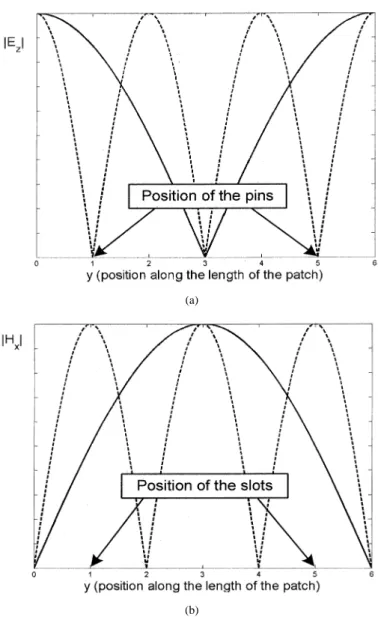
Considering that microstrip antennas are resonant structures and can resonate at many discrete frequencies, they are bound to operate more than one frequency by nature. However, the dual-frequency operation with just a single patch antenna is mostly useful if the antenna over both frequency bands of interest has similar radiation patterns, polarizations and input impedance characteristics. Therefore, in the design of dual-band microstrip antennas, one needs to decide on the useful modes of resonance satisfying these constraints. For example, if an antenna is to be designed for linear polarization on the same direction over both frequency bands, then the two lowest useful modes of resonance are (0,1) and (0,3) modes according to the cavity model. Fur-thermore, since the frequencies associated with these modes are fixed (the ratio of the frequencies of the modes is 3), they need to be tuned according to the specification of the required bands of frequencies. In this respect, shorting pins (or strips) located between the patch and the ground plane and slots in the patch geometry play very important roles in tuning the modal frequen-cies to the desired frequenfrequen-cies. By properly placing the shorting pins under the patch or slots in the patch, the ratio of the frequen-cies corresponding to the lowest useful cavity modes, namely (0,1) and (0,3), can be adjusted to any value less than 3. Note, that a shorting pin placed at the nodal lines of (0,3) mode does not affect the resonant frequency of (0,3) mode significantly, but increases the resonant frequency of (0,1) mode, by forcing the electric field to be zero at the position of the shorting pin as seen in Fig. 1(a). Similarly, when a slot is placed on the patch where the magnetic field of (0,3) mode is maximum, the radia-tion from the slot results in a perturbaradia-tion of the field distriburadia-tion that gives rise to a decrease in the operating frequency of (0,3) mode [Fig. 1(b)].
Brief review of the cavity model in conjunction with the mul-tiport analysis for a microstrip antenna with shorting strips and slots is provided in Section II. Then, the design process of mi-crostrip antennas with strips and slots via the genetic optimiza-tion algorithm is discussed in Secoptimiza-tion III, where some exam-ples and discussions on the proposed algorithm for the design of multifrequency antennas are also included. In addition, the
(a)
(b)
Fig. 1. Cavity modes of the patch antenna (solid line: (0,1) mode, dashed line: (0,3) mode).
electrical characteristics of the designed antennas, as obtained by the multiport analysis, are compared to those obtained exper-imentally and to those obtained by the full-wave method, HFSS by ANSOFT. This is followed by the conclusion in Section IV.
II. CAVITYMODELWITHSHORTINGPINS ANDSLOTS
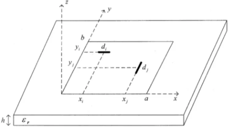
The cavity model was first proposed in 1979 for probe-fed mi-crostrip antennas [11]. Since then, the method has been further improved to predict the input impedance of microstrip antennas with multiple strips or slots, and to cover microstrip antennas fed by slots in the ground plane [17], [19], [27]. The major re-striction of the cavity model is on the thickness of the substrate, which is supposed to be not more than a few hundredths of a wavelength. This is mainly because the model assumes that nei-ther field components nor the source can be a function of the vertical coordinate under the patch. As a result of this assump-tion, the electric field has only z component, while the mag-netic field has only x and y components in the region bounded by the microstrip patch and the ground plane, Fig. 2. In addition, using the fact that the electric current density on the microstrip
Fig. 2. Geometry of a microstrip antenna with onex-directed probe feed and oney-directed shorting pin.
patch has no normal component along the edge of the patch, the tangential magnetic field is assumed to be negligible not just at the edges of the patch but all the way down to the ground plane. Therefore, the region between the patch and the ground plane can be surrounded by perfect magnetic conductor (PMC) wall that would not significantly alter the original field distribu-tion under the patch, and hence forms a cavity. Consequently, once the cavity is formed as the model of the patch antenna, the fields in the cavity and subsequently other electrical character-istics can be easily obtained by the well-known solution of the cavity.
A. Multiple Shorting Strips
With the use of the above stated assumptions on the field directions and variations, and the boundary conditions of the cavity, the electric field anywhere under the patch can be obtained, for a 1 Amp. uniform probe current located at a point ( , ), as [19]
(1) where
is the eigenvalue of the (m,n) mode, ,
is the quality factor of the cavity, and ( , ) and are the effective dimensions of the patch and effective width of the feeding strip extended laterally in x direction, respectively. Since the electric field is constant along z direction, the voltage created by th source at any point under the patch can simply be written as . Hence, the self and mutual impedances, and , for the z polarized uniform current densities on any two strips, as shown in Fig. 2, can be calculated by averaging the voltage generated by the th source over the extend of the th shorting strip . The shorting strips could be extended laterally either in the same direction
Fig. 3. Geometry of a microstrip antenna with one probe feed and two slots.
or in perpendicular directions and the mutual impedances are obtained as
(2)
where the upper and lower expressions in each curly bracket are for the lateral extensions of x and y directions, respectively, for the strips, and . Since the main goal of the multiport analysis is to get the effect of the shorting strips on the input impedance, there is no need to assign the feeding probe a priori, that is, any strip can be the feeding probe or shorting strip. For an N-port microstrip antenna, the input impedance seen at port-i can be calculated by assigning zero voltage (short circuit) to all ports except the ith port. In this case, the port currents are related to each other in the following form:
(3) where is the impedance matrix from which th row and th column have been extracted, is the th row of the impedance matrix, and are the port current and voltage vectors, respectively, all with the th entries are extracted. Su-perscript 1 and denote the inverse and transpose operators, respectively. By using (3), the input impedance seen at port-i is obtained as
(4)
B. Multiple Slots
For the sake of illustration, a patch with two perpendicularly oriented slots with the lengths of and and a vertical strip with the width of is demonstrated in Fig. 3. Note, that only very narrow slots are considered in this work, and all the lengths
(5)
where the matrix is of a hybrid type, mixed with impedance , admittance , current gain and voltage gain parameters. Since there is only one vertical strip, which is used for feeding, in this example and throughout this study, only exists in this formulation. However, this approach can be easily extended to multiple vertical strips and slots together, for which case the characterization matrix would be formed by block matrices of , , , and . Referring back to the example given in Fig. 3, the parameter has already been introduced in (2); the others can be obtained easily from the following definitions:
(6)
(7)
(8)
(9)
where denotes the magnetic volume current density at the slot j(k) and the volume below it down to the ground plane, and the field components are defined with the two subscripts: the first defines the polarization of the field; and the second defines the port that was generated from. Note that slots are modeled as uniform magnetic current densities, not only at the surface where slots reside but also in the volume just below it down to the ground plane [19], [27]. The reason for the extension of the magnetic current at the slot into the volume below is that, as it was mentioned in the introduction, source models used in the cavity model must be independent of the coordinate perpendic-ular to the patch in the substrate.
Once the matrix representation of the patch with a feed and slots is obtained, the input impedance seen by the probe feed can be obtained in terms of the load admittances and across the slot terminals at port-j and port-k, respectively [28]. By using
In summary, the multiport analysis of a microstrip antenna with some shorting pins and/or slots is performed by following these steps: 1) vertical strips (shorting or feeding) and slots are considered as the ports of an N-port network; 2) voltage and cur-rent sources are assigned to the slots and vertical strips, respec-tively; 3) independent parameters of the ports (voltage and cur-rent for strips and slots, respectively) are written in terms of the dependent parameters (current and voltage for strips and slots, respectively); 4) circuit parameters, like impedance, admittance, current gain and voltage gain, are obtained by short-circuiting some slots and by open-circuiting some strips; and finally 5) the input impedance at the feed port is obtained in terms of the cir-cuit parameters, and hence the effects of the slots or strips on the input impedance are quantitatively obtained.
III. RESULTS ANDDISCUSSION
After having introduced and reviewed the cavity model and multiport analysis of microstrip antennas with shorting strips and slots, these approaches have been combined with a robust optimization algorithm, the genetic algorithm. Since the genetic algorithm has been well studied and reviewed in the literature [31]–[33], it is not repeated here in detail. Instead, the steps of the algorithm are provided for being able to discuss the pa-rameters used in the optimization algorithm. The first step is to code the parameters of the optimization as finite length strings (chromosomes), then to generate a population of these strings, which will be multiple starting points as contrary to a single ini-tial point in gradient based optimization algorithms. Therefore, this approach increases the probability of finding the global op-timum by searching the whole parameter space in parallel. The next step is to evaluate the cost function at each member of the population and to assign some fitness value. Then, the genetic algorithm employs some probabilistic transition rules (random-ized operators) to guide the search for optimum, which are re-production, crossover and mutation.
A. Multiple strips
In this study, the genetic optimization algorithm was first used to find the appropriate locations and widths of the shorting strips in a microstrip patch antenna to match the input impedances to 50 at both low and high frequencies and to satisfy a de-sired frequency ratio , where and denote the high and low frequencies, respectively, for a dual-band operation. For the optimization, the feed location, its width and orientation, the number of shorting strips, their orientations and the desired fre-quency ratio are used as known and fixed parameters, while the
and coordinates, and the width of each shorting strip are used as the optimization parameters. So, the objective function is written as
(11)
where is the desired frequency ratio, and
are the input impedances at and , respectively, and 100 is just a positive number determined empirically to make maximum at the point of optimization.
For the presentation of the algorithm discussed so far in this paper, two microstrip antennas with some shorting strips have been designed for dual-band operation via the genetic optimiza-tion algorithm. The first example is an air-filled antenna and its fixed parameters are as follows: cm, cm,
cm, mho cm, , the position
of the feed, cm cm , the width of the feed, cm and the lateral extension of the feed is in direc-tion.
The genetic algorithm has five internal properties: chromo-some length, population size, generation number, crossover probability, and mutation probability. Since each variable parameter, real or integer, is transformed into a binary string with the length defined by the precision required for that variable, the chromosome length is the length of the member in the population, that is, the length of the binary string combined for all variables. For the study of these two antennas, the chromosome length is chosen as 25 chromosomes per unknown parameter, so that the total length of each chromosome (or a member in the population) for a patch with shorting strips is , 3 being the number of the variable parameters for each strip. The crossover probability and mutation probability used are 0.65 and 0.008, respectively, and two-point crossover is applied in each trial. The population size and generation number determine the speed and efficiency of the genetic algorithm. The optimization parameters and results for the air-filled antenna with at most two shorting strips for different population sizes and generation numbers are given in Table I, where ( , ) and ( , ) denote the coordinates of the first and second strips, respectively, and are the widths of the strips, while and G are the population size and the generation number, respectively, and is the desired frequency ratio. To guide the search algorithm, the limits of the and coordinates of the shorting strips are determined by the patch dimensions, while the strip widths are varied in the range of 0.1–1.5 cm. Case-1 corresponds to the patch with one shorting strip extended laterally in direction, case-2 and case-3 correspond to the patches with two shorting strips: the former has both strips extended in x direction, the latter has one extended in x direction and the other extended in y direction.
For the first antenna, with the optimized positions and widths of the shorting strips given in Table I, the simulation results are provided in Table II. To assess the accuracy of the simulation technique used in conjunction with the optimization algorithm, the results of a full-wave approach, namely HFSS, are also pro-vided. It is observed from Table II that the resonant frequencies and the reflection coefficients for both low and high bands agree very well with those predicted by HFSS.
TABLE I
OPTIMIZATIONPARAMETERS ANDRESULTS FOR THEAIR-FILLEDANTENNA
(DIMENSIONS INCENTIMETERS)
TABLE II
SIMULATIONRESULTS FOR THEAIR-FILLEDANTENNA
TABLE III
RESONANTFREQUENCIES ANDREFLECTIONCOEFFICIENTS FOR THE
DIELECTRIC-FILLEDANTENNA
TABLE IV
OPTIMIZATIONPARAMETERS ANDRESULTS FORf =f = 2:7
The second antenna was designed to demonstrate the appli-cability of the proposed algorithm for microstrip antennas over a dielectric material , for which the fixed parameters
are: cm, cm, cm, mho cm,
, cm cm , cm.
For dual frequency operation, this antenna was designed with
one shorting strip located at cm, cm, and
with a width of cm, extending in x direction laterally. The low and the high resonance frequencies together with the reflection coefficients at resonance are presented and compared in Table III.
From the designs of these two dual-band antennas, a total of four cases, it is observed that the antennas designed by the ge-netic optimization algorithm with the multiport analysis agree with the specifications, as confirmed by the results of a rigorous
(a)
(b)
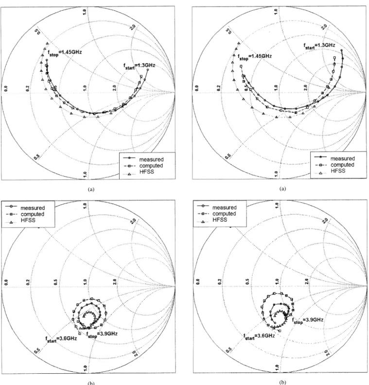
Fig. 4. Measured and computed impedance loci of the first patch antenna in Table IV: (a) low band and (b) high band.
full-wave method, HFSS. This observation suggests that the al-gorithm presented here can make an efficient and accurate CAD tool, at least for the initial design of dual-band microstrip an-tennas with multiple shoring strips. Another point worth noting is that, during the design iterations, the strip locations tend to converge to the nodal field lines of the third cavity mode, as expected.
B. Multiple Slots
The proposed design algorithm for microstrip antennas, which is the multiport analysis in conjunction with the cavity
(a)
(b)
Fig. 5. Measured and computed impedance loci of the second patch antenna in Table IV: (a) low band and (b) high band.
model and genetic optimization algorithm, is further tested on microstrip antennas with slots etched in the patch, with a view of designing dual-band antennas. For this study, a rectangular patch antenna (made of bronze) fed by a vertical strip is de-signed with the following fixed parameters: cm,
cm, cm, , , S m,
cm cm , and cm. As in the case
of the patch antenna with shorting strips, the goal of the opti-mization is again to find the appropriate coordinates and length of the slots used, to satisfy the specifications on the frequency
ratio and on the input impedance over the high and low fre-quency bands. So, using the objective function defined in (11),
x and y coordinates, and the length of each slot are optimized. It
is worth mentioning that the cavity model is applicable to patch antennas with narrow slots, therefore the width of each slot is fixed to 0.15 cm. For the optimization algorithm, the chromo-some length, crossover and mutation probabilities are set to 20 (for each optimization parameter), 0.65 and 0.008, respectively. Also, two-point crossover is used in each process.
The frequency ratio is set to 2.7, and optimizations are per-formed for different numbers of x oriented slots. In each opti-mization with different number of slots, the population size and generation number are fixed to 1000 and 200, respectively. The optimization results are summarized in Table IV, where the first column gives the number of x oriented slots, and the last column gives the optimized positions and lengths of the slots. For all the cases studied here, the specifications on the frequency ratio and the input impedances have been very well satisfied. To verify the optimization results, the first and second optimized antennas in Table IV were realized and tested experimentally. Then, the input impedances obtained from the multiport analysis in con-junction with the cavity model, from measurements and from HFSS are compared over both low and high bands as shown in Figs. 4 and 5.
It is observed from Table IV that the design algorithm pre-sented in this paper provides positions and lengths of the slots quite accurately for the design of dual-band microstrip antennas. The input impedance loci presented in Figs. 4 and 5 imply that the multiport method proposed in this paper performs well, as far as the accuracy is concerned.
IV. CONCLUSION
Dual-frequency operation of rectangular patch antennas with shorting strips and slots has been investigated via the cavity model in conjunction with the multiport theory. By combining this approach with the genetic optimization algorithm, an ef-ficient and accurate design tool was proposed for dual-band microstrip antennas using multiple vertical strips or slots. For the examples provided in this study, the frequency ratio of the high-band and low-band frequencies, and the input impedances over these bands were used as the specifications, while the coor-dinates and dimensions of the strips or slots were the optimiza-tion parameters. The antennas so designed have been realized, and dual-band operation was verified experimentally as well as by simulation of the antennas rigorously via HFSS by Ansoft. It is observed that the theoretical results agree well with the exper-imental results. Therefore, this approach can be safely proposed as an efficient CAD tool for dual-band microstrip antennas that would use slots or vertical strips, at least for the initial design of the antennas.
APPENDIX A IMPEDANCE OF ASLOT
The impedance of a slot in an infinite ground plane can be approximately obtained by the impedance of a short dipole via well-known Babinet’s principle [29], [30]
(A.1)
where is the intrinsic impedance of the free space, and the dipole is assumed to be the complement of the slot. Since the input impedance of a short dipole can be modeled as a series connection of radiation resistance, ohmic resistance, inductance, and capacitance, which are expressed as follows [30]:
(A.2)
where is the magnitude of the current distribution, and is the half-length of the dipole
(A.3)
(A.4) (A.5)
where s is the half of the gap provided for the voltage source, and is the radius of the dipole, i.e., is the width of the slot. Hence, the input impedance of the short dipole is obtained as
(A.6)
REFERENCES
[1] N. Herscovici, “A wide-band single-layer patch antenna,” IEEE Trans. Antennas Propagat., vol. 46, pp. 471–474, Apr. 1998.
[2] , “New considerations in the design of microstrip antennas,” IEEE Trans. Antennas Propagat., vol. 46, pp. 807–812, June 1998. [3] J.-Y.Jia-Yi Sze and K.-L.Kin-Lu Wong, “Slotted rectangular microstrip
antenna for bandwidth enhancement,” IEEE Trans. Antennas Propagat., vol. 48, pp. 1149–1152, Aug. 2000.
[4] K. L. Wong and J. Y. Jan, “Broadband circular microstrip antenna with embedded reactive loading,” Electron. Lett., vol. 34, pp. 1804–1805, 1998.
[5] J. R. James and G. Andrasic, “Multifunction printed antennas,” in Ad-vances in Microstrip and Printed Antennas, K. F. Lee and W. Chen, Eds. New York: Wiley, 1997.
[6] J. F. Zurcher, A. Skrivervik, O. Staub, and S. Vaccaro, “A compact dual-port dual-frequency printed antenna with high decoupling,” Mi-crow. Opt. Technol. Lett., vol. 19, pp. 131–137, Oct. 1998.
[7] M. Kijima, Y. Ebine, and Y. Yamada, “Development of a dual-frequency base station antenna for cellular mobile radios,” IEICE Trans. Commun., vol. E82-B, pp. 636–643, Apr. 4, 1999.
[8] J. F. Zürcher, Q. Xu, A. Skrivervik, and J. R. Mosig, “Dual-frequency, dual-polarization four port printed planar antenna,” Microw. Opt. Technol. Lett., vol. 23, pp. 75–78, Oct. 20, 1999.
[9] G. S. Binoy, C. K. Aanandan, P. Mohanan, K. Vasudevan, and K. G. Nair, “Single-feed dual-frequency dual-polarized slotted square microstrip antenna,” Microw. Opt. Technol. Lett., vol. 25, pp. 395–397, June 20, 2000.
[10] D. M. Pozar and J. R. James, “A review of CAD for microstrip an-tennas and arrays,” in Microstrip Anan-tennas: The Analysis and Design of Microstrip Antennas and Arrays, D. M. Pozar and D. H. Schaubert, Eds. New York: IEEE Press, 1995.
[11] Y. T. Lo, D. Solomon, and W. F. Richards, “Theory and experiment on microstrip antennas,” IEEE Trans. Antennas Propagat., vol. AP-27, pp. 137–145, Mar. 1979.
tion of a microstrip radiator with multiple lumped linear loads,” Elec-tromagn., vol. 3, no. 3–4, pp. 371–385, July–Dec. 1983.
[18] S. C. Pan and K. L. Wand, “Dual frequency triangular microstrip an-tenna with shorting pin,” IEEE Trans. Anan-tennas Propagat., vol. 45, pp. 1889–1891, Dec. 1997.
[19] B. F. Wang and Y. T. Lo, “Microstrip antennas for dual-frequency op-eration,” IEEE Trans. Antennas Propagat., vol. 32, pp. 938–943, Sept. 1984.
[20] Y. M. M. Antar, A. I. Ittipiboon, and A. K. Bhattacharyya, “A dual fre-quency antenna using a single patch and an inclined slot,” Microw. Opt. Technol. Lett., vol. 8, pp. 309–311, Apr. 20, 1995.
[21] J. H. Lu, “Dual-frequency operation of a single-feed rectangular microstrip antenna with a pair of comb-shaped slots,” Microw. Opt. Technol. Lett., vol. 23, pp. 183–186, Nov. 5, 1999.
[22] , “Slot-loaded rectangular microstrip antenna for dual-frequency operation,” Microw. Opt. Technol. Lett., vol. 24, pp. 234–237, Feb., 20 2000.
[23] K.-L.Kin-Lu Wong, M.-C.Mon-Chun Pan, and W.-H.Wen-Hsiu Hsu, “Single-feed dual-frequency triangular microstrip antenna with a V-shaped slot,” Microw. Opt. Technol. Lett., vol. 20, pp. 133–134, Jan. 20, 1999.
[24] J. Y. Jan and K. L. Wong, “Single-feed dual-frequency circular mi-crostrip antenna with an open-ring slot,” Microw. Opt. Technol. Lett., vol. 22, no. 3, pp. 157–159, Aug. 1999.
[25] L.Lakhdar Zaid, G.Georges Kossiavas, J.-Y.Jean-Yves Dauvignac, J.Josiane Cazajous, and A.Albert Papiernik, “Dual-frequency and broad-band antennas with stacked quarter wavelength elements,” IEEE Trans. Antennas Propagat., vol. 47, pp. 654–660, Apr. 1999.
[26] S. O. Kundukulam, M.Manju Paulson, C. K. Aanandan, P. Mohanan, and K. Vasudevan, “Dual-band dual-polarized compact microstrip antenna,” Microw. Opt. Technol. Lett., vol. 25, pp. 328–330, June 5, 2000. [27] M. I. Aksun, S. L. Chuang, and Y. T. Lo, “On slot-coupled microstrip
antennas and their applications to CP operation—theory and experi-ment,” IEEE Trans. Antennas Propagat., vol. AP-38, pp. 1224–1230, Aug. 1990.
[28] P. K. Park and C. T. Tai, “Receiving antennas,” in Antenna Handbook, Y. T. Lo and S. W. Lee, Eds. New York: Van Nostrand Reinhold, 1993. [29] R. F. Harrington, Time-Harmonic Electromagnetic Fields. New York:
McGraw-Hill, 1961.
[30] M. Kominami, D. M. Pozar, and D. H. Schaubert, “Dipole and slot el-ements and arrays on semi-infinite substrates,” IEEE Trans. Antennas Propagat., vol. AP-33, no. 6, pp. 600–607, June 1985.
[31] D. E. Goldberg, Genetic Algorithms in Search, Optimization, and Ma-chine Learning. Reading, MA: Addison-Wesley, 1989.
[32] F. J. Ares-Pena, J. A. Rodriguez-Gonzalez, E. Villaneuva-Lopez, and S. R. Rengarajan, “Genetic algorithms in the design and optimization of antenna array patterns,” IEEE Trans. Antennas Propagat., vol. 47, p. 506, Mar. 1999.
[33] J. M. Johnson and Y. Rahmat-Samii, “Genetic algorithms and method of moments (GA/MOM) for the design of integrated antennas,” IEEE Trans. Antennas Propagat., vol. 47, p. 1606, Oct. 1999.
Selma Mutlu was born in Turkey on January 22,
1975. She received the B.S. and M.S. degrees in electrical engineering from Bilkent University, Ankara, Turkey, in 1998 and 2001, respectively.
Currently, she is a Software Developer at Basari Company, Ankara. Her research interests include numerical electromagnetics, microstrip antennas and microwave theory.
M. I. Aksun (M’92–SM’99) received the B.S. and M.S. degrees in electrical
and electronics engineering at the Middle East Technical University, Ankara, Turkey, in 1981 and 1983, respectively, and the Ph.D. degree in electrical and computer engineering at the University of Illinois at Urbana-Champaign, in 1990.
From 1990 to 1992, he was a Postdoctoral Pellow in the Electromagnetic Communication Laboratory at the University of Illinois at Urbana-Champaign. From 1992 to 2001, he was on the faculty of the Department of Electrical and Electronics Engineering at Bilkent University, Ankara, Turkey, where he was a Professor since 1999. In 2001, he joined the Department of Electrical and Electronics Engineering at Koc University, Istanbul, Turkey, as a Professor. His research interests include numerical methods for electromagnetics, microstrip antennas, indoor and outdoor propagation models, and microwave and millimeter-wave integrated circuits.
Lale Alatan (S’91–M’97) received the B.S., M.S.,
and Ph.D. degrees in electrical engineering from the Middle East Technical University (METU), Ankara, Turkey, in 1990, 1993, and 1997, respectively.
From 1997 to 1998, she was a Postdoctoral Fellow in the Electrical and Computer Engineering Department at Carnegie Mellon University, Pitts-burgh, PA, and from 1998 to 1999, in the Electrical and Computer Engineering Department at the New Jersey Institute of Technology, Newark. Currently, she is an Assistant Professor with the Electrical and Electronics Engineering Department at METU. Her research interests include numerical analysis of printed structures, microstrip antennas, phased arrays, and optimization techniques.