Genetic Algorithm Based Broadband Equalizer
Design with Ripple Level Control
Metin Şengül
Faculty of Engineering and Natural Sciences Kadir Has University
Cibali-Fatih, Istanbul, Turkey [email protected]
Atilla Özmen
Faculty of Engineering and Natural Sciences Kadir Has University
Cibali-Fatih, Istanbul, Turkey [email protected]
Abstract— In this paper, broadband equalizer design with ripple control via genetic algorithm has been studied. The equalizer is defined as a lossless two-port terminated by load impedance, and the coefficients of its describing scattering polynomials have been optimized via genetic algorithm. During the optimization process, ripple level of the transducer power gain has been controlled. An example has been given to illustrate the utilization of the proposed approach.
Keywords-genetic algorithm; broadband; matching; ripple I. INTRODUCTION
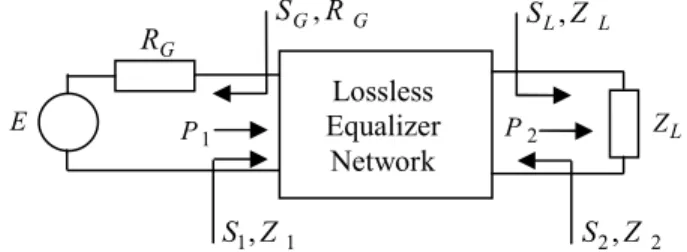
The matching problem is the design of a lossless two-port network between a generator and complex load impedance. It is desired to maximize the transfer of power from the source to the load over the interested frequency band. To measure the power transfer capability of the lossless equalizer network, the transducer power gain that is defined as the ratio of power delivered to the load to the available power from the generator is utilized.
Figure 1. Broadband Matching problem.
Let us consider the circuit arrangement shown in Fig. 1. Here if the generator is ideally matched to the load, the power transferred to the load is equal to the available power from the generator (P2 = ). This is possible only if the impedance P1 seen at the input of the equalizer is equal to the generator resistance (Z1=RG), but as well known this can be realized at
only a single frequency, not over a frequency band. If a broadband matching is desired, then the following points must be considered: The maximum tolerance on the match, the minimum bandwidth within which the match is to be obtained
and the degree of the network. The given load impedance mainly defines the gain bandwidth limitations. Thus, the broadband matching problem involves two main considerations:
• Determining the gain bandwidth limitations of given load impedance,
• Finding the equalizer topology to obtain the best possible performance.
The matching problem can be classified basically as filter, single matching, double matching and active two-port problems. If both terminating impedances are resistive, it is a filter problem. In single matching problem, generator impedance is resistive and load impedance is complex. If both terminating impedances are complex, then the problem is referred to as the double matching problem. If the input and output of an active device is simultaneously matched to given load and generator impedances, then this is called as the active two-port problem. Design of a microwave amplifier is a typical example of this matching problem.
The analytic matching theory requires a circuit realization for the terminating impedances. But in practice experimental real frequency data for the terminating impedances are given. So to be able to use analytic theory, these data should be modeled by an analytic realizable function. Also an analytic form of gain function suitable for the given terminating impedances must be found. But unfortunately these are possible only for simple problems having terminations with one or two reactive elements. The load in the most complicated case solved by the analytic theory in literature consists of two reactances and one resistor, which is matched over a low-pass band. But the solution is not simple. If the number of reactive elements in the load network increases, even though the analytic theory is applicable in principle, it may lead to more complicated results [1-3].
On the other hand, matching networks can be designed by utilizing commercially available computer aided circuit design tools such as Microwave Office, ADS, etc. [4,5]. But these programs based on purely numerical methods, and they are
G R L Z E 1 P P2 1 1, Z S S2, Z 2 G G R S , S ,L Z L Lossless Equalizer Network 978-1-4673-1448-0/12/$31.00 ©2012 IEEE
actually devised for final trimming of given networks. Namely, the circuit topology and suitable initials of the element values should be supplied to these programs. Here, the main problem is the determination of optimum circuit topology. Moreover, the performance function is highly nonlinear in terms of the unknown element values. As a result, it is necessary for the element values to be close enough to the final solution for guaranteeing the convergence to a global optimum. For narrow band design problems with a few numbers of elements, the circuit topology and the initial element values may not be very critical. In these cases, satisfactory solutions can be achieved by trial and error. But, for broadband matching problems, if the optimum circuit topology is unknown, the use of these programs may result suboptimal solutions. Therefore, such computer aided design tools are suitable for final optimization of the element values.
As a result of the above discussion, both the analytic theory and numerical methods have several problems and usually are not applicable for solving most matching problems. Therefore, previous studies in the literature have pointed the task of developing more practical methods to design matching networks, which can directly utilize measured numerical data. So the problems associated with the analytic theory and numerical techniques have been overcome.
The method called real frequency technique (RFT) proposed by Carlin in 1977 removes the main problems of the analytic theory and numerical methods [1]. The method utilizes directly the experimental real frequency data for the terminating impedances, and it is not necessary to find neither the analytic form of the transfer function nor the equalizer circuit topology. Also it has been shown in lots of single matching problems that the real frequency technique results in better performance with simpler structures than the designs obtained with analytic theory [1,2,6]. Because of these advantages, the real frequency technique has been the most preferable approach to solve broadband matching problems.
So far many researchers have developed some alternative real frequency approaches [7-23]. Some of them can be listed as seen below.
• Line segment technique (LST) • Direct computational technique (DCT) • Parametric approach
• Simplified real frequency technique (SRFT)
In this paper, a genetic algorithm based broadband equalizer design algorithm has been proposed. There exists a ripple level control mechanism in the method. So in the pass band flatter transducer power gain curve has been obtained than that of the existing methods.
Since in the proposed technique to represent the lossless equalizer network the canonic polynomial representation of the scattering matrix will be used in a similar manner like SRFT, in the next section SRFT is summarized.
II. SIMPLIFIED REAL FREQUENCY TECHNIQUE (SRFT) In the first three methods listed above, driving point impedance is used to describe the lossless equalizer. However, the matching problem can be formulated in terms of any other set of functions such as scattering or chain parameters of the lossless equalizer network. In the real frequency scattering approach called as the Simplified Real Frequency Technique (SRFT), the canonic polynomial representation of the scattering matrix is utilized to describe the lossless matching network [8,24,25].
Referring to the matching configuration depicted in Fig. 1, the normalized scattering parameters of the lossless two-port can be written in terms of three real polynomials using the well-known Belevitch representation as follows:
), ( / ) ( ) ( ), ( / ) ( ) ( ), ( / ) ( ) ( ), ( / ) ( ) ( 22 21 12 11 p g p h p S p g p f p S p g p f p S p g p h p S − − = = − = = μ μ (1)
where g( p) is a strictly Hurwitz polynomial, f( p) is a real monic polynomial and μ is a unimodular constant (μ=±1). If the two-port is reciprocal, then the polynomial f( p) is either even or odd and μ= f(−p)/f(p).
The polynomials
{
f(p),g(p),h(p)}
can be related by the Feltkeller equation as ) ( ) ( ) ( ) ( ) ( ) (p g p h ph p f p f p g − = − + − , (2)then the following degree relations can be obtained:
n p f n p h( )≤ , deg ( )≤
deg where n=degg(p).
It can be concluded from these equations that the Hurwitz polynomial g(p) is a function of h(p) and f(p) . If the polynomials f(p) and h(p) are known and then the network can be defined completely.
The polynomial f(p) that is constructed on the zeros of transmission of the two-port is defined by the user, who has an idea about the location of transmission zeros of the equalizer network. If the designer is interested in ladder type of realizations (reciprocal realizations without coupled coils), then the form of the polynomial f(p) can be written as follows
(
)
∏
= + = 2 1 0 ) ( 2 2 k i k i a p p p f (3)where k and 1 k are nonnegative integers and 2 a ’s are i
arbitrary real coefficients. This form corresponds to ladder type of minimum phase networks, whose transmission zeros are located on the imaginary axis of the complex p plane. −
Once the complexity of the equalizer, the form of f(p) and the coefficients of the polynomial h(p) are determined, then the polynomial g(p) can be generated as a Hurwitz polynomial by explicit factorization of (2). Namely the scattering parameters
{
Sij, i,j=1,2}
and the matching network can be determined by finding the suitable coefficients of the polynomial h(p). Then the transducer power gain of the network is optimized.The transducer power gain of the two-port can be expressed in terms of the normalized scattering parameters of the two-port and the termination impedances as follows: Referring to Fig. 1, the transducer power gain of the lossless equalizer can be written as 2 1 1 ) (ω = −ρ T (4)
where ρ is the input reflection coefficient which can be 1 expressed as G G R Z R Z + − = 1 1 1 ρ . (5)
Here, Z is the driving point input impedance of the 1
equalizer when its output port is loaded by Z . On the other L
side let S and G S denote the real-normalized reflection 1
coefficients at port 1; 1 1 , 1 1 1 1 1 + − = + − = Z Z S R R S G G G . (6)
Substituting the inverse relationships from (6) in (5) in conjunction with (4) results the transducer power gain as a function of S and G S as follows: 1
2 1 2 1 2 1 1 1 ) ( S S S S T G G − ⎟ ⎠ ⎞ ⎜ ⎝ ⎛ − ⎟ ⎠ ⎞ ⎜ ⎝ ⎛ − = ω . (7)
It is known that S1 can be written in terms of the scattering
parameters of the two-port and the reflection coefficient of ZL
as L L S S S S S S 22 2 12 11 1 1 − + = . (8)
Substituting (8) in (7) and by manipulation, the following relation can be obtained
2 2 2 11 2 2 21 2 1 1 1 1 ) ( L G L G S S S S S S S T − − ⎟ ⎠ ⎞ ⎜ ⎝ ⎛ − ⎟ ⎠ ⎞ ⎜ ⎝ ⎛ − = ω , (9) where G G L L L S S S S S S Z Z S 11 2 21 22 2 1 , 1 1 − + = + − = .
Here, note that S2 represents the output reflection coefficient of the equalizer when its input port is terminated in
G
R . Substituting the polynomial forms of the scattering parameters given by (1) into (9), transducer power gain can be expressed in terms of the polynomials f(p),g(p) and h( p) as
(
)(
)
(
* *)
2 2 2 2 1 1 ) ( g S h S S h g f S S T G L G L G − + − − − = μ ω . (10)As a summary, the transducer power gain T(ω) of the matching network can be generated from the polynomial h( p). The unknown coefficients hi , ( i=0,1,2,…,n ) of the
polynomial h( p) can be determined by employing any nonlinear optimization technique in such a way that the
computed gain T(ω) approximates the required gain level over the interested frequency band.
III. GENETIC ALGORITHM
Genetic algorithm is a heuristic search algorithm that inspired by the biological evolution process and used to find the solution of the optimization problems. Algorithm is started with a set of possible solutions. This set of solutions is called as population and represented by chromosomes.
One common application of genetic algorithm is function optimization. This algorithm can be applied to discrete optimization problems, where derivate-based optimization methods cannot be used.
A. Genetic Algorithm Operators
The basic form of genetic algorithm consists of three types of operators: selection, crossover and mutation [26]. Selection operator selects chromosomes in the population for reproduction. Crossover decomposes two distinct solutions and then randomly mixes their parts to form new solutions. Mutation randomly alters some of gene values in a chromosome from its initial state. This operation results in new gene values and better solutions values can be obtained from this new gene values.
A simple genetic algorithm works as follows [26]:
1. Start with a randomly picked population. (Produce candidate solutions to a problem.)
2. Calculate the fitness values of each chromosome in the population.
3. Create new solutions (offspring) by repeating the following steps:
• Using fitness probabilities select a pair of parent chromosomes from the current population.
• Cross over the pair at a randomly chosen point to form two offspring.
• Mutate the two offspring and place the obtained chromosomes in the new population.
• Replace the current population with the new population.
Repeat process by starting from fitness value calculation step.
IV. PROPOSED MATCHING ALGORITHM
Step 1: Set minimum and maximum ripple levels as TL and
U
T , respectively.
Step 2: Set the number of elements in the equalizer as n .
Step 3: Choose the form of the polynomial f( p) according to (3) such that deg f(p)≤n.
Step 4: Find the roots of the even polynomial
) ( ) ( ) ( ) (ph p f p f p
coefficients of the polynomial h( p),
{
hi, i=0,1,2,…,n}
, is going to be optimized.Step 5: From the left half plane roots, form the polynomial
) ( p
g .
Step 6: Knowing
{
f(jω),g(jω),h(jω)}
and{
SG(jω),SL(jω)}
compute the transducer power gain using (10).
Step 7: Define the following error function at each frequency points:
( )
ω ω ε ,k 1,2, ,N therwise , 1 T , 0 L … = ⎩ ⎨ ⎧ ≤ ≤ = o T T k U k (11)where Nω represents the total number of frequency points.
Step 8: Calculate the following objective function:
∑
= = ω ε δ N k k 1 (12) If the total error is acceptable, then synthesize the corresponding impedance function) ( ) ( ) ( ) ( ) ( p h p g p h p g p z − + = .
Otherwise, change hi coefficients via genetic algorithm and go to Step 4.
V. EXAMPLE
In this section an example is given to illustrate the utilization of the proposed algorithm.
For the problem under consideration, the load network is specified by Fig. 2. It includes a parallel combination of a resistance R=1, and a capacitor C=4.
Figure 2. Load impedance with normalized element values. From the analytic theory, it is known that for this load configuration, maximum flat transducer power gain level is 0.79 approximately. So minimum and maximum ripple levels are defined as TL =0.75 and TU =0.79, respectively.
The number of elements in the equalizer is selected as 4
=
n . Suppose a simple low pass LC ladder is desired as equalizer network. Then the polynomial f( p) is selected as
1 ) (p = f .
After running proposed algorithm, the following back-end reflection function is obtained as
) ( ) ( ) ( 22 g p p h p S =−μ − where 1μ= f(−p)/ f(p)= , 5594 . 0 1027 . 1 5699 . 0 1801 . 0 7479 . 0 ) (p = p4− p3− p2− p− h , 1458 . 1 8874 . 2 3855 . 3 4390 . 2 7479 . 0 ) (p = p4+ p3+ p2+ p+ g
The same problem is solved by using SRFT. The initial
coefficients
(
hi,i=0,1,2,…,n)
are selected arbitrarily as 1 , 1 , 1 , 1 , 1 1 2 3 4 0 = h =− h = h =− h =h . Then the following
reflection function is obtained as ) ( ) ( ) ( 22 g p p h p S =−μ − where 1μ= f(−p)/ f(p)= , 5031 . 0 3301 . 1 4425 . 0 7418 . 0 3117 . 1 ) (p = p4− p3− p2− p− h , 1194 . 1 2452 . 3 1124 . 4 5354 . 3 3117 . 1 ) (p = p4+ p3+ p2+ p+ g .
Synthesized equalizers are shown in Fig. 3.
Figure 3. Designed equalizer network, (Genetic: C1=4.878, C2=1.9297,
57111 . 0 1= L , L2=0.47512, RG=0.34334. SRFT: C1=4.9516, 4747 . 2 2= C , L1=0.61335, L2=0.56663, RG=0.3795).
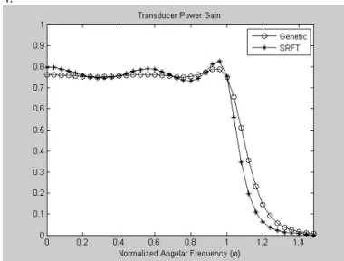
Also the transducer power gain curves are depicted in Fig. 4.
Figure 4. Transducer power gain plots.
As can be seen in Fig. 4, the curves fluctuate near to 79
. 0 =
T , but the transducer power gain curve obtained from genetic based approach is flatter in the pass band (has very small ripple) than that of the curve obtained via SRFT.
The curve obtained via SRFT is a Chebyshev-like curve; there are ripples in the passband, and the transition region is narrow. On the other hand, there is a very small ripple in the passband, and the transition region is wide for the curve obtained via genetic algorithm. So this curve is a Butterworth-like curve. As a result, while the ripple level decreases, the transition region gets wider.
) ( ) ( ) ( 22 p gh pp S = 4 = C 1 = R 1 C 2 C 1 L 2 L G R L Z 4 = C R=1
VI. CONCLUSION
In this work, a genetic algorithm based broadband equalizer design algorithm has been proposed. The coefficients of the polynomial h( p) which is one of the three polynomials describing the equalizer in Belevitch notation has been optimized by using genetic algorithm. There exists a ripple level control mechanism in the method. So in the pass band flatter transducer power gain curve has been obtained than that of SRFT, but a wide transition region is resulted, as seen in the example.
REFERENCES
[1] H. J. Carlin and P. Amstutz, “On optimum broadband matching,” IEEE Trans. CAS, vol. 28, pp. 401-405, May 1981.
[2] B. S. Yarman, “Broadband matching a complex generator to a complex load,” PhD dissertation, Cornell University, 1982.
[3] H. J. Carlin and P. P. Civalleri, “On flat gain with frequency dependent terminations,” IEEE Trans. CAS, vol. 32, pp. 827-839, Aug. 1985. [4] Microwave Office of Applied Wave Research Inc. (www.appwave.com). [5] Advanced Design Systems (ADS) of Agilent Technologies.
(www.home.agilent.com).
[6] B. S. Yarman, “Real frequency broadband matching using linear programming,” RCA Review, vol. 43, pp. 626-654, Dec. 1982.
[7] H. J. Carlin and B. S. Yarman, “The double matching problem: analytic and real frequency solutions,” IEEE Trans. CAS, vol. 30, pp. 15-28, Jan. 1983.
[8] B. S. Yarman, “A simplified real frequency technique for broadband matching complex generator to complex loads,” RCA Review, vol. 43, pp. 529-541, Sept. 1982.
[9] B. S. Yarman, “Modern approaches to broadband matching problems,” Proc. IEE, vol. 132, pp. 87-92, Apr. 1985.
[10] A. Fettweis, “Parametric representation of brune functions,” Int. J. Circuit Theory and Appl., vol. 7, pp. 113-119, 1979.
[11] J. Pandel and A. Fettweis, “Broadband matching using parametric representations,” in IEEE Int. Sym. Circuit and Systems, Kyoto, Japan, vol. 41, pp. 143-149, 1985.
[12] J. Pandel and A. Fettweis, “Numerical solution to broadband matching based on parametric representations,” Int. J. Electron. Commun. (AEU), vol. 41, pp. 202-209, 1987.
[13] B. S. Yarman and A. Fettweis, “Computer aided double matching via parametric representation of brune functions,” IEEE Trans. CAS, vol. 37, pp. 212-222, Feb. 19980.
[14] C. Beccari, “Broadband matching using the real frequency technique,” in IEEE Int. Sym. Circuits and Systems, May 1984, Montreal, Canada, vol. 3, pp. 1231-1234.
[15] P. Jarry and A. Perennec, “Optimization of gain and vswr in multistage microwave amplifier using real frequency method,” in European Conf. Circuit Theory and Design, Sept. 1987, Paris, France, vol. 23, pp. 203-208.
[16] W. T. Hatley, “Computer analysis of wide band impedance matching networks,” Tech. report no.6657-2, Stanford University, Stanford Electronics Laboratories, Stanford, CA, 1967.
[17] A Kılınç, H. Pınarbaşı, M. Şengül and B. S. Yarman, “A broadband microwave amplifier design by means of immitance based data modeling tool,” in IEEE 6th Africon Conf., Oct. 2002, George, South
Africa, vol. 2, pp. 535-540.
[18] B. S. Yarman, M. Şengül and A. Kılınç, “Design of practical matching networks with lumped elements via modeling,” IEEE Trans. CAS-I, vol. 54(8), pp. 1829-1837, Aug. 2007.
[19] B. S. Yarman and E. G. Çimen, “Design of a broadband microwave amplifier constructed with mixed lumped and distributed elements for mobile communication,” in 1st Int. Conf. Circuits and Syst. for Comm.,
Jun. 2002, vol. 26-28, pp. 334-337.
[20] A. Aksen and B. S. Yarman, “A parametric approach to describe distributed two-ports with lumped discontinuities for the design of broadband MMIC’s,” in Proc. IEEE Int. Sym. CAS, May 2003, Thailand, vol. 1, pp. 249-252.
[21] M. Şengül and B. S. Yarman, “Real frequency technique without optimization,” in 4th Int. Conf. Electrical and Electronics Eng., Dec.
2005, Bursa, Turkey, vol. 1, pp. 261-265.
[22] P. Lindberg, M. Şengül, E. Çimen, B. S. Yarman, A. Rydberg and A. Aksen, “A single matching network design for a dual band pifa antenna via simplified real frequency technique,” in 1st European Conf. Antennas
and Tech., Nov. 2006, Nice, France, .
[23] B. S. Yarman at all, “Design of broadband matching networks,” in ECT 07, (Invited talk), Jan. 2007, Okinawa, Japan.
[24] B. S. Yarman and H. J. Carlin, “A simplified real frequency technique applied to broadband multi stage microwave amplifiers,” IEEE Trans. MTT, vol. 30, pp. 2216-2222, Dec. 1982.
[25] B. S. Yarman, Design of Ultra Wideband Power Transfer Networks, Wiley, 2010.
[26] M. Mitchel, An Introduction to Genetic Algorithms, A Bradford Book The MIT Press, Cambridge, Massachusetts, London, England, 1999.