Article in International Journal of Mechatronics and Manufacturing Systems · May 2014 DOI: 10.1504/IJMMS.2014.067166 CITATIONS
0
READS315
2 authors: Some of the authors of this publication are also working on these related projects: Strain Gradient PlasticityView project
Samad Nadimi Bavil Oliaei Atilim University 40 PUBLICATIONS 140 CITATIONS SEE PROFILE Yigit Karpat Bilkent University 50 PUBLICATIONS 1,166 CITATIONS SEE PROFILEOn-machine fabrication of PCD and WC micro end
mills using micro electro discharge machining
Samad Nadimi Bavil Oliaei
Department of Mechanical Engineering, Bilkent University,
06800 Ankara, Turkey
Email: samad.nadimi@bilkent.edu.tr
Cem Özdemir
Department of Industrial Engineering, Bilkent University,
06800 Ankara, Turkey Email: cemo@bilkent.edu.tr
Yiğit Karpat*
Department of Industrial Engineering, Bilkent University,
06800 Ankara, Turkey and
Department of Mechanical Engineering, Bilkent University,
06800 Ankara, Turkey Email: ykarpat@bilkent.edu.tr *Corresponding author
Abstract: Micro electro discharge machining (µ-EDM) process can be used to
fabricate micro-milling tools of different geometries from tungsten carbide (WC) and polycrystalline diamond (PCD). The non-contact nature of EDM process makes micro tool fabrication a challenging task while offering the advantage of eliminating tool run out and clamping errors since micro tools fabricated on-machine. The tools are fabricated and used on the same spindle. In this study, a combination of block-EDM and wire electro discharge grinding (WEDG) techniques are used to fabricate micro end mills of different geometries. The influences of EDM process parameters on material erosion rate and surface roughness are examined. The performance of the fabricated micro-tools in ductile mode machining of fused silica has been investigated. It is found that micro end mills can be used to fabricate prototypes of microfluidics chips with acceptable quality.
Keywords: electrical discharge machining; micro machining; micro milling. Reference to this paper should be made as follows: Oliaei, S.N.B., Özdemir, C.
and Karpat, Y. (2014) ‘On-machine fabrication of PCD and WC micro end mills using micro electro discharge machining’, Int. J. Mechatronics and Manufacturing Systems, Vol. 7, Nos. 4/5/6, pp.246–264.
Biographical notes: Samad Nadimi Bavil Oliaei is a PhD candidate in
Mechanical Engineering Department at the Bilkent University. His research interests focuses on micromachining processes with specific emphasis on the micro tool fabrication using micro processing techniques.
Cem Özdemir received his MSc from Bilkent University in Industrial Engineering. His research focus is on development of decision support systems for manufacturing processes.
Yiğit Karpat received his BSc from Dokuz Eylül University, and his MSc from Middle East Technical University, both in Mechanical Engineering. In 2007, he received his PhD in Industrial/Manufacturing Engineering from Rutgers University and joined Bilkent University as an Assistant Professor. He currently holds dual appointments in the Department of Industrial Engineering and the Department of Mechanical Engineering at Bilkent, where he pursues research on modelling material/process interactions in manufacturing and is actively involved in the Micro System Design and Manufacturing Center established at Bilkent University.
This paper is a revised and expanded version of a paper entitled ‘Fabrication of micro ball end mills using micro electro discharge machining’ presented at 7th International Conference on Design and Production of Dies and Molds, Antalya, Turkey, 20–23 June 2013.
1 Introduction
The demand for fabrication of micro parts from advanced ceramics and glass materials such as silicon carbide, silicon nitride, soda lime glass and fused silica has been increasing. Various grades of glass have found numerous applications in the manufacturing of micro fluidic devices for biological analysis, thanks to their superior material properties such as high homogeneity, high hardness, corrosion resistance, temperature stability and low coefficient of thermal expansion (Richardson, 1992; Daridon et al., 2001; Petersen et al., 2004). Among various kinds of glasses available in the market, fused silica has been widely employed in various domains of micro system technology including biomedical and optical systems, especially for generating micro channels which are an integral part of micro fluidic devices. It can be considered as a proper material for different applications, if it can be economically machined with acceptable quality. One promising process to achieve this goal is the use of micro-milling operations using polycrystalline diamond (PCD) and tungsten carbide (WC) micro-tools. In these kind of processes on-machine micro-tool fabrication concept is becoming popular, since micro-tools are fabricated on the same spindle which are also used in machining operations. This enables manufacturers to achieve the required accuracy and to avoid tool wear and breakage by eliminating the errors due to tool run out and tool holding system.
In addition to the processing of ceramics, on-machine fabricated micro-tools are necessary as a part of miniaturisation trend in the modern industry, which demands the production of higher functionality structural and mechanical components with significantly decreased manufactured features in the range of a few to a few hundred microns for applications in the aerospace, automotive, optics, electronics, medicine,
biotechnology, communications, defence and avionics, to name a few (Liu et al., 2004; Chae et al., 2006; Lai et al., 2008). Specific applications include microscale fuel cells, gas and liquid chromatography, electrophoresis, polymer chain reaction, chemical analysis systems, micro reactors and microelectronics cooling, microscale pumps, valves and mixing devices, microholes for fibre optics, micronozzles for high-temperature jets, micromolds, deep X-ray lithography masks, and many more such as Liu et al. (2004), Chae et al. (2006), and Rossetti et al. (2010). Advantages such as capability of processing non-silicon-based materials, the ability to generate complex three-dimensional freeform surfaces and shapes with high aspect ratios, being environmentally friendly and eliminating the need for expensive clean room facilities and costly photolithographic masks, make these processes unique. In order to implement tool-based micro machining techniques in a technically rigorous, profitable, and consistent fashion, there are a number of scientific and technological challenges that must be overcome.
The aim of this study is to address micro end mill fabrication using a multi-processing technique which combines block-EDM and wire electro discharge grinding (WEDG). Different machining strategies which include wear compensation of the sacrificial tungsten block and wire diameter effect are employed to obtain the desired shape with a very tight tolerances. This study is important because micro-tools are an important and integral part of the mechanical micromachining process. Their quality, stiffness and toughness have a direct influence on the machined parts, which largely depends on the fabrication method and material used for their construction. On-machine micro-tool fabrication which incorporates a combination of block-EDM and WEDG in a single setup followed by a micromilling/grinding process on the desired workpiece can be considered as an efficient and reliable method in the micro-fabrication industry. In this study, WC and PCD are used as a tool material for the fabrication of micro end mills.
Machining of PCD has become one of the major concerns of the manufacturers for the last few decades (Mahdavinejad, 2005). Processing PCD by using mechanical processes like diamond grinding seems to be economically unfeasible because of the high wear rate of diamond wheels and arduous processing. Therefore, non-contact processes such as micro electro discharge machining and focused ion beam milling (FIB) can be used to process PCD tools without applying any force. FIB technique is considerably more expensive and slower compared to EDM, but very sharp edges can be machined by means of FIB (Cheng and Huo, 2013).
In this study, first experimental setup is explained and EDM processes utilised here are briefly summarised. The influence of EDM process parameters on material erosion rate and surface roughness are investigated using experimental techniques. Different shapes of micro tools are then fabricated and the performances of the fabricated micro end mills are tested by machining micro channels on fused silica glass. Tool wear and surface finish are observed under various machining conditions. Machining of fused silica in a ductile mode to avoid brittle fracture and crack generation are investigated.
2 Experimental setup
The experiments were carried out in a hybrid micro-machine tool (DT-110, MIKROTOOLS) available in Micro System Design and Manufacturing Center of Bilkent
University. This machine can perform multiple machining processes such as micro turning, micro milling, micro EDM, micro wire EDM and WEDG. The measurement of the processed parts can be performed using an on-machine measurement device. Figure 1 illustrates micro EDM setup used in this study.
Figure 1 Micro EDM setup (see online version for colours)
Pure tungsten (99.9%) was used as a sacrificial electrode in block-EDM process and brass wire of 200 µm diameter has been used for WEDG. WC and PCD rods are mounted on a spindle (up to 5,000 rpm). Open voltage can be selected in the range of 80 to 130 V and capacitance can be set within the range of 10 pF to 400 nF. EDMfluid 108 MP-S is used as a dielectric fluid for all EDM processes described in this study. It has a medium viscosity and a flash point of 108°C. In order to obtain complex geometries and desired clearance and rake angles, special indexing device has been designed, fabricated and integrated into the DT-110, MIKROTOOLS.
3 WEDG and block-EDM processes
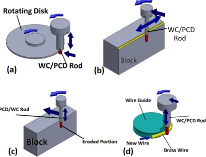
Figure 2 illustrates four main types of EDM techniques that are used to fabricate micro tools. Each process has its own advantages and disadvantages. For the case of rotating disk EDM method [Figure 2(a)], the run-out of the rotating disk may reduces the accuracy. Block-EDM and stationary block EDM processes [Figure 2(b) and Figure 2(c)] are not accurate enough because of the wear of the sacrificial tungsten block.
Figure 2 EDM-based fabrication techniques, (a) rotating disk method (b) block EDG
(c) stationary block EDM (d) WEDG (see online version for colours)
Figure 2(d) shows the WEDG which is known to be the most common technique to fabricate micro tools having various shapes. The principle of fabricating micro tools with this technique, proposed by Masuzawa et al. (1985), is illustrated in Figure 3.
Figure 3 WEDG method to fabricate micro tools (see online version for colours)
Source: Masuzawa et al. (1985)
A translating wire is used to erode the tool material where the tool is given positive polarity and the wire has negative polarity. Dielectric fluid (oil) is used to initiate and maintain sparks during the EDM process. A specific tool path needs to be determined by the user depending on the final shape of the micro tool. In order to obtain axisymmetric tool shapes, the tool is rotated. It is also possible to obtain asymmetric shaped tools. In this case, tools must follow their paths without rotating. In this study, a special fixture has been designed and integrated to the spindle which allows for accurate angular positioning of the tool with respect to wire. This fixture also makes it possible to obtain micro tools
with complex geometries as well as improved rake and flank faces. Once the tool is fabricated, it is possible to perform micro milling or micro grinding process without removing the micro tool from the spindle. A disadvantage of WEDG process is that, it has a low material erosion rate. Therefore, this technique is particularly suitable for finishing.
Recently, Rahman et al. (2007) used a pure tungsten block as a sacrificial electrode to erode PCD and WC tool materials to obtain micro cutting tools. This technique yields faster tool material erosion rate than the WEDG method. However, maintaining the dimensional accuracy of the machined rod is not straightforward since the block also wears out during the process. Pure tungsten is used as a sacrificial electrode due to its high melting temperature. In block-EDM process, programmed depth of cut, discharge gap, and sacrificial electrode wear determine the final dimension of the fabricated tool. These parameters reduce to two in WEDG as the wear of the sacrificial electrode is compensated by feeding a new wire to the machining zone.
Discharge energy is the most dominant surface roughness controlling parameter in all EDM processes, because it determines the size of the EDM induced craters on the workpiece. Higher discharge energies produce larger craters which increase surface roughness. However, in the processing of PCD by EDM, diamond grain size is another surface roughness controlling parameter. Diamond grains also introduce some differences in removal mechanism. As reported by Masaki et al. (2007) for larger energy discharges the induced craters on PCD was smaller than WC, and the craters on PCD tools were not like a shallow bowl as can be observed in WC tools. Considering the basic mechanism of PCD electro-discharge machining, i.e., the melting of binder (normally Cobalt or Nickel) and falling off of diamond grains, it is expected to observe shallow craters on the PCD tool. Recently, it has been reported by Zhang et al. (2013) that at extremely low discharge energies, removal rate of cobalt binder can be suppressed to avoid the falling off of diamond grains, which enables gradual removal of diamond grains by microstructural changes through graphitisation and thermo-mechanical reactions. These two mechanisms are of great importance depending on the application of the fabricated micro-tools. For the case of micro grinding tools rough surface of the PCD tool containing lots of sharp diamond grains are preferred, while for micro milling tools very low discharge energies seems to be suitable because this machining conditions not only gives a good surface finish but also gives a smaller tool edge radius, thus reduces plowing forces during machining.
In this study, block-EDM technique is used for rough electro discharge machining followed by WEDG technique for finish electro discharge machining. To investigate the effects of EDM process parameters on the material erosion rate and surface roughness of PCD and WC micro tools, some experiments have been performed. These are explained in the next section.
4 Experimental investigation of the effect of process parameters on MER and surface quality
A design of experiments approach has been used to investigate the influence of EDM process parameters on the material erosion rate when machining WC tool material using WEDG technique. WC blanks of 3 mm diameter with ultra fine grain size are used. Their diameters are reduced to 700 µm (±5 µm) using block-EDM technique. Three process
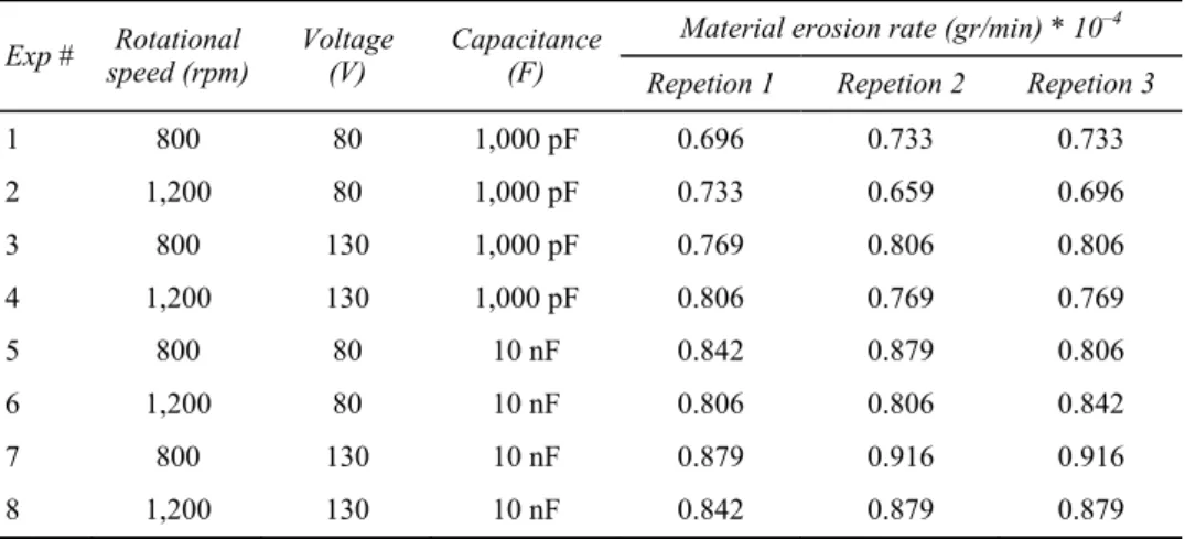
parameters at two levels were considered such as voltage (80–130 V), capacitance (1,000 pF–10 nF), and rotational speed of the spindle (800–1,200 rpm). The experiments were repeated three times. Therefore, a total of 24 experiments was performed at the conditions listed in Table 1. All experiments were performed at a fixed duration of time, and the amount of eroded material was measured by weighing the rods before and after the experiments. Measured erosion rates along with experimental conditions are listed in Table 1.
Table 1 List of experimental conditions
Exp # speed (rpm) Rotational Voltage (V) Capacitance (F) Material erosion rate (gr/min) * 10
–4
Repetion 1 Repetion 2 Repetion 3
1 800 80 1,000 pF 0.696 0.733 0.733 2 1,200 80 1,000 pF 0.733 0.659 0.696 3 800 130 1,000 pF 0.769 0.806 0.806 4 1,200 130 1,000 pF 0.806 0.769 0.769 5 800 80 10 nF 0.842 0.879 0.806 6 1,200 80 10 nF 0.806 0.806 0.842 7 800 130 10 nF 0.879 0.916 0.916 8 1,200 130 10 nF 0.842 0.879 0.879
The experimental results were analysed by using a statistical analysis software and the results are shown in Figure 4. It can be seen that, as capacitance and voltage increases, material erosion rate increases. There is an inverse relationship between rotational speed and material erosion rate within the experimental range tested.
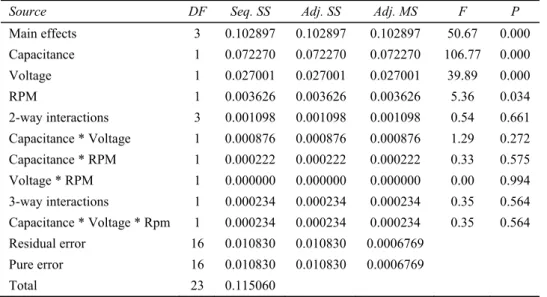
Table 2 shows the analysis of variance (ANOVA) results obtained from the statistical analysis. It can be concluded that the capacitance has the most significant effect on the material erosion rate which is followed by the voltage. The effect of rotational speed is not influential on the results based on 95% confidence interval. Based on the findings, a regression model between capacitance, voltage and rotational speed can be written as in equation (1).
Table 2 ANOVA table
Source DF Seq. SS Adj. SS Adj. MS F P
Main effects 3 0.102897 0.102897 0.102897 50.67 0.000 Capacitance 1 0.072270 0.072270 0.072270 106.77 0.000 Voltage 1 0.027001 0.027001 0.027001 39.89 0.000 RPM 1 0.003626 0.003626 0.003626 5.36 0.034 2-way interactions 3 0.001098 0.001098 0.001098 0.54 0.661 Capacitance * Voltage 1 0.000876 0.000876 0.000876 1.29 0.272 Capacitance * RPM 1 0.000222 0.000222 0.000222 0.33 0.575 Voltage * RPM 1 0.000000 0.000000 0.000000 0.00 0.994 3-way interactions 1 0.000234 0.000234 0.000234 0.35 0.564 Capacitance * Voltage * Rpm 1 0.000234 0.000234 0.000234 0.35 0.564 Residual error 16 0.010830 0.010830 0.0006769 Pure error 16 0.010830 0.010830 0.0006769 Total 23 0.115060 MER 0.802792 0.054875 Capacitance 0.0335417 Voltage 0.0122917 RPM = + + − (1)
In order to test the influence of EDM process parameters on the surface quality, some additional tests were performed on the WC and PCD tools. The block – EDM technique was used to fabricate stepped tools as shown in Figure 5. Different processing parameters were applied while electro discharge machining at each region. Surface roughness at each region was measured by using Keyence VK-100 laser surface topography microscope.
Figure 5 (a) Tip of the WC tool (b) Tip of the PCD tool
Table 3 illustrates the surface roughness values obtained at each region as a function of process parameters. As expected, decreasing voltage and capacitance resulted in better surface roughness. PCD tool material with 5 µm grain size yielded better surface quality than WC tool material.
Table 3 Surface roughness measurements (at 500 rpm) Region 1 V = 130 V C = 400 nF Region 2 V = 105 V C = 10 nF Region 3 V = 80 V C = 100 pF WC 5.55 µm 4.47 µm 2.7 µm PCD 3.44 µm 1.76 µm 1.7 µm
5 Fabrication of micro end mills using WEDG technique
Micro end mills can be produced in various forms and geometries depending on the intended applications. In this study, fabrication process of three common types of micro tools, i.e., micro ball end mills, cylindrical D-shape, and lollipop end mills are investigated.
5.1 Fabrication of D-shaped square end cylindrical micro end mills
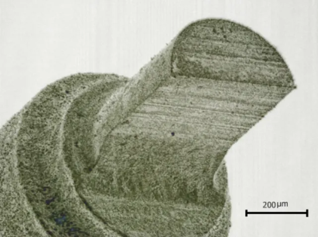
Cylindrical D-shaped micro tool is the simplest micro end mill geometry which shows a good performance in micro machining. To fabricate these micro tools, a PCD or WC blank rod is mounted on the spindle, and its diameter has been reduced to the desired dimension while spindle is rotating. After the desired diameter has been obtained, spindle rotation is stopped and in-feed and feed motions are employed to obtain the D shape. Figure 6 illustrates the fabricated D-shaped micro tool through WEDG process.
5.2 Fabrication of ball end mills
The challenging issue regarding the fabrication of micro-ball end mills using wire electro-discharge grinding process is the motion of the tool with respect to the wire. The wire diameter is also an important parameter since the size of the wire and the tool are in the same order of magnitude. Neglecting the wire size in micro-WEDG process may result in large differences between the desired and fabricated micro features. Therefore, regular circular interpolation commands cannot be directly applied in micro-ball end mill fabrication. In an attempt to compensate for the wire size effect in micro ball end mill fabrication following tool trajectory has been developed. To successfully apply this strategy, it is necessary to select a suitable zero point for the workpiece (denoted by O in Figure 7). From Figure 7, we have
o o X OS OP PS Z SO LN ′ ′ = = + ′ = = (2)
Using trigonometric relations we have:
(1 cos ) 2 sin 2 T W o T W o D D X D D Z ′ ′ + ⎛ ⎞ =⎜ ⎟ − ⎝ ⎠ + ⎛ ⎞ = ⎜⎝ ⎟⎠ φ φ (3)
For micro-ball end mill fabrication using WEDG, the angle φ should be in the range of
. 2
π
≤ ≤
0 φ
Figure 7 The designation used for wire diameter compensation in this study (see online version
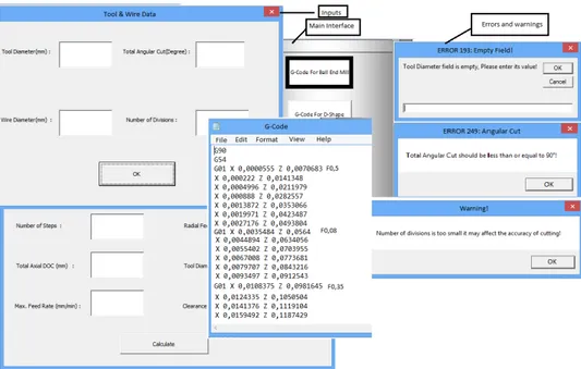
Figure 8 User interface and generated G-code for the fabrication of micro ball end mills
(see online version for colours)
Figure 10 Micro ball end mills fabricated through WEDG process, (a) PCD tool (b) WC tool
(see online version for colours)
(a) (b)
It must be noted that, when tool diameter and wire diameter changes, the user has to recalculate the tool path. In order to automate the tool path generation process for the fabrication of ball end mills, a computer code has been developed. The user interface of the computer code is shown in Figure 8. The software takes necessary process parameters as input and calculates the tool path and generates the G-code as shown in Figure 8. G-code can be entered directly into the CNC EDM machine and the tool fabrication process can be started. It is also possible to estimate the total processing time of the fabrication by using the same software.
Figure 9 shows the micro ball end mills fabricated through WEDG process. Figure 9 shows the dimensional accuracy of the ball end mill which is designed to have 400 µm diameters. The radius of the hemispherical part of the tool is measured using laser topography microscope. It can be seen that the radius calculated through 3 points around 199 µm which satisfies the requirement of fabrication.
Once the hemispherical shape of the tool tip is obtained, half of the tool tip is eroded away using WEDG without rotating the tool to obtain the cutting edge. Figure 10 shows the PCD and WC micro ball end mills.
Tool’s cutting edge radius is known to be influential on the machining performance. Figure 11 shows that edge radius of the PCD tool is around 12 µm. This value can be further reduced by employing a different PCD material with smaller grain size. The diameter of the PCD ball end mill is measured as 700 µm.
5.3 Fabrication of lollipop end mills
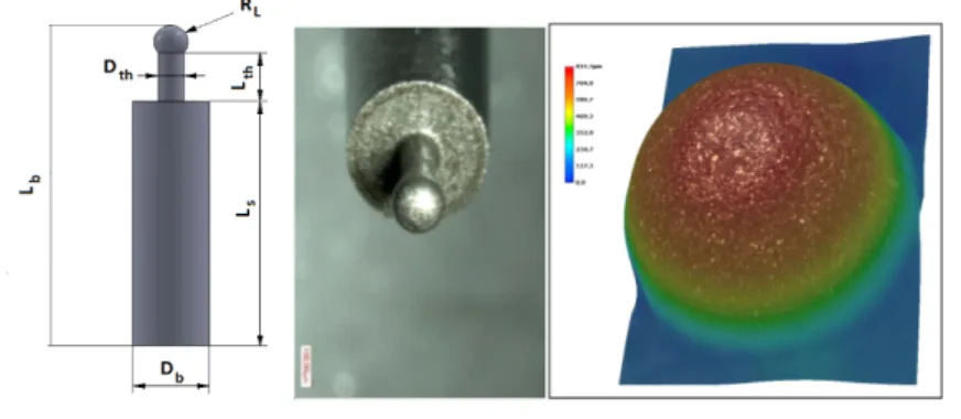
Lollipop end mills are effective cutters for milling complex geometries and profiles, and cutting of round surfaces with an undercut. In this study, a novel method has been introduced to fabricate micro lollipop end mills using block-EDM technique. This method requires some modifications of the sacrificial pure tungsten block which can be done through micro-milling operations. The diameter of the blank rod (Db) is reduced to a
diameter of the Lollipop micro-mill (2 × RL) giving an appropriate depth of cut in the
axial direction and simultaneous movement in longitudinal (X) and transverse directions (Y). The movement in Y direction should be controlled to achieve the desired diameter (2 × RL) taking into account sacrificial electrode wear and spark gap. The next step is to
use a modified sacrificial tungsten electrode to machine the throat of the end mill with a length of Lth and diameter of Dth. The width of the machined step determines Lth and
again an appropriate controlled movement in Y direction is necessary to obtain Dth. In the
final step, modified sacrificial tungsten electrode which includes a hemispheric channel of radius of RL obtained by micro-milling is used to give a final shape to the tool. It
should be mentioned that the top portion of the block should also be modified based on Dth of the tool. In the last step of the operation, the machined tool is brought in an
appropriate position according to the desired dimensions of the tool and machined features of the block, and Block-EDM is performed using appropriate machine movements. Figure 12 illustrates the fabricated micro end mill by this method.
Figure 12 Lollipop end mill fabricated through block-EDM (see online version for colours)
6 Micro milling of fused silica with on-machine fabricated micro end mills
The aim of this section is to investigate the performance of micro mechanical machining of fused silica using PCD and WC micro ball end mills. Brittle materials like glass and ceramics have low machinability in terms of surface integrity as they undergo brittle fracture during machining processes which leads to chipping, surface and sub-surface macro/micro-cracks and non-transparent surfaces. Ductile mode machining of brittle materials can be done to prevent fracture-based damage from transferring onto the machined surface (Arif et al., 2012). It is a well-known fact that the scale of the overall deformation process has a significant influence on the degree of brittleness. In a study conducted by Lawn et al. (1976) a depth has found at which brittle material failure during indentation changed from plastic deformation to brittle fracture. This depth is called critical depth of cut. Later, it was confirmed by Bifano et al. (1991) that in brittle materials, transition in deformation regime from brittle to ductile occurs as the depth of cut decreases. Material removal energy can be used to describe the transition from brittle to ductile machining regime, where in ductile mode machining plastic flow is a more energetically favourable material removal mechanism which became dominant as the scale of deformation decreases. In the present study micro-cutting experiments have been done to determine the critical depth of cut for fused silica glass.
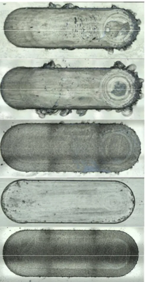
Pressure and temperature in the cutting zone together with the undeformed chip thickness are significantly important factors affecting the cutting transition from brittle regime to ductile regime. Different machining parameters and tool geometries provide different cutting regimes by altering the pressure and temperature in the cutting zone. In this study in order to obtained ductile mode machining, different tool geometries are designed and fabricated and tested under different machining conditions. Rake and clearance angle of the tools has been changed to see the effect of tool geometry on the brittle to ductile cutting transition. Depth of cut, feed rate spindle speed, dry/wet cutting are also examined to obtain ductile mode machining on fused silica. Figure 13 shows how the quality of micro channels changes as a result of change in cutting conditions and tool geometry. It is clear from Figure 13 that wet cutting under oil provides better surface quality compare to the dry cutting condition. In addition it can be found that a tool with a 10° clearance angle shows a good performance compare to the tool with zero clearance angle, since it eliminates the frictional contact of the tool and workpiece and avoids
accumulation of powder like chips under the cutting tool. Taking into account various machining parameters and tool geometries, as it has been shown in Figure 13, a successful improvement in the quality of the micro channels has been done by selecting a correct tool and machining configuration.
Figure 13 Variation of channel quality with tool geometry and cutting conditions
(see online version for colours)
a) PCD tool, zero clearance angle at the bottom, DOC: 10 μm, f: 0.5 mm/min, dry-cutting
b) PCD tool, zero clearance angle
at the bottom, DOC: 10 μm, f: 0.75 mm/min, dry-cutting
c) PCD tool, zero clearance angle at the bottom, DOC: 10 μm, f: 0.5 mm/min, oil-cutting
d) PCD tool, 10° clearance angle at the bottom, DOC: 10 μm, f: 0.25 mm/min, oil-cutting
e) PCD tool, 10° clearance angle at the bottom, DOC: 10 μm, f: 0.5 mm/min, oil-cutting
Note: Milling was performed with the PCD tool shown in Figure 6.
Micro milling experiments on fused silica was performed using PCD and WC ball end mills. Different slot micro milling conditions were tested to investigate the performances of the fabricated micro tools. Surface roughness of the micro milled surfaces were also investigated. Figure 14(a) shows the profile of the micro channel machined with the 400 µm diameter PCD micro ball end mill. The depth of the micro channel was measured as 15 µm and the surface roughness of the bottom of the micro channel is measured as 0.3 µm as shown in Figure 14(b). In the experiment, rotational speed was set at 2,000 rpm and feed rate was set at 1 mm/min. The quality of the micro channel is acceptable. No fracture around the channel walls were observed.
Figure 14 (a) Profile of the micro channel machined with 400 µm PCD micro ball end mill
(b) Surface roughness of the micro channel (see online version for colours)
(a) (b)
A PCD ball end mill with a larger diameter (700 µm) was also employed to machine deeper micro channels. Figure 15(a) shows the micro channel with 265 µm depth machine at 2,000 rpm and 1 mm/min feed rate. The shape of the PCD tool profile is reflected on the milled channel. It has bull end shape rather than ball end. The surface integrity of the channels in down milling side is obviously better than the up milling direction. The surface roughness at the bottom of the channel is measured as 0.74 µm.
Figure 15 (a) Profile of the micro channel machined with 700 µm PCD micro ball end mill
(b) Surface roughness of the micro channel (see online version for colours)
(a) (b)
Figure 16 shows the PCD end mills after machining experiments. Due to larger depth of cut, a significant amount of fused silica material stuck onto the tool material [Figure 16(a)]. Due to low depth of cut, only the tip portion of the PCD ball end mill wore out.
Figure 16 PCD micro end mills after machining experiments, (a) 700 µm diameter (b) 400 µm
diameter (see online version for colours)
(a) (b)
Similar experiments were also conducted with WC end mills (520 µm diameter). Figure 17 shows the profile of the micro channel after machining. The profile can be used to measure the diameter of the ball end mill as shown in Figure 17(b). The surface roughness were measured as 0.47 µm at the bottom of the first micro milled channel.
Figure 17 (a) Profile of the micro channel machined with 520 µm diameter WC micro ball end
mill at N = 2,000 rpm, ap = 30 µm, f = 0.5 mm/min (b) Measurement of tool diameter from the machined surface (see online version for colours)
(a) (b)
The depth of cut is increased to 70 µm under the same machining conditions. The profile of the channel is shown in Figure 18(a). Some uncut glass at the side of the channels can be seen from the measurements. The experiments were conducted at this condition and the profile of the channel after milling 5 more channel with 5 mm length is shown in Figure 18(b). Figure 18(c) shows the micro ball end mill after machining experiments. It can be seen that the tool is severely damaged during cutting which is reflected on the machined surface. Some micro cracks on the bottom of the surface are visible.
Figure 18 (a) Profile of the micro channel machined with 520 µm diameter WC micro ball end
mill at N = 2,000 rpm, ap = 70 µm, f = 0.5 mm/min (b) machined surface with the worn tool of tool (c) worn WC micro ball end mill (see online version for colours)
(a) (b)
(c)
7 Conclusions
In this study, a combination of block-EDM and WEDG was used to fabricate micro end mills of different diameters from WC and PCD. It has been shown that micro ball end mills having 400 µm diameter can be successfully fabricated after implementing wire diameter compensation in WEDG. The fabricated micro tools performed satisfactory results in producing micro channels of different aspect ratios on fused silica glass. Ductile mode machining of fused silica with good surface quality was obtained. A computer code with user friendly interface was developed by the authors and it can be used as an effective tool for the fabrication of micro-ball end mills.
Acknowledgements
The authors would like to thank The Scientific and Technological Research Council of Turkey (TÜBİTAK) through Grant 110M660 (National Young Researcher Career Development Program) and Ministry of Development of Turkey (HAMIT-Micro System Design and Manufacturing Research Center) for their support for this work.
References
Arif, M., Rahman, M., San, W. Y. (2012) ‘A model to determine the effect of tool diameter on the critical feed rate for ductile-brittle transition in milling process of brittle material’, Journal of Manufacturing Science and Engineering, Vol. 134, No. 5, pp.0510121–8.
Bifano, T.G., Dow, T.A. and Scattergood, R.O. (1991) ‘Ductile-regime grinding: a new technology for machining brittle materials’, Journal of Engineering for Industry, Vol. 113, pp.184–189. Chae, J., Park, S.S. and Freiheit, T. (2006) ‘Investigation of micro-cutting operations’ International
Journal of Machine Tools & Manufacture, Vol. 46, pp.313–332.
Cheng, K. and Huo, D. (Eds.) (2013) Micro-Cutting: Fundamentals and Applications, 1st ed., John Wiley & Sons Ltd.
Daridon, A., Fascio, V., Lichtenberg, J., Wütrich, R., Langen, H., Verpoorte, E. and Rooij, N.F. (2001) ‘Multi-layer microfluidic glass chips for microanalytical applications: Fresenius’, Journal of Analytical Chemistry, Vol. 371, No. 2, pp.261–269.
Lai, X., Li, H., Li, C., Lin, Z. and Ni, J. (2008) ‘Modelling and analysis of micro scale milling considering size effect, micro cutter edge radius and minimum chip thickness’, International Journal of Machine Tools & Manufacture, Vol. 48, No. 1, pp.1–14.
Lawn, B.R., Jensen, T. and Arora, A. (1976) ‘Brittleness as an indentation size effect’, Journal of Materials Science, Vol. 11, pp.573–575.
Liu, X., DeVor, R.E., Kapoor, S.G. and Ehmann, K.F. (2004) ‘The mechanics of machining at the microscale: assessment of the current state of the science’, Transactions of the ASME, Journal of Manufacturing Science and Engineering, Vol. 126, No. 4, pp.666–677.
Mahdavinejad, R.A. (2005) ‘ED machining of WC-Co’, Journal of Material Processing Technology, Vols. 162–163, pp.637–643.
Masaki, T., Kuriyagawa, T., Yan, J. and Yoshihara, N. (2007) ‘Study on shaping spherical poly crystalline diamond tool by micro-electro-discharge machining and micro-grinding with the tool’, International Journal of Surface Science and Engineering, Vol. 1, No. 4, pp.344–359. Masuzawa, T., Fujino, M. and Kobayashi, K. (1985) ‘Wire electro-discharge grinding for
micro-machining’, CIRP Annals – Manufacturing Technology, Vol. 34, No. 1, pp.431–434. Petersen, D., Mogensen, K.B. and Klank, H. (2004) Glass Micromachining, in Microsystem
Engineering of Lab-on-a-Chip Devices, edited by O. Geschke, H. Klank and P. Telleman, Wiley-VCH Verlag GmbH & Co. KGaA, Weinheim, FRG.
Rahman, M., Lim, H.S., Neo, K.S., Senthil Kumar, A., Wong, Y.S. and Li, X.P. (2007) ‘Tool-based nanofinishing and micromachining’, Journal of Materials Processing Technology, Vol. 185, Nos. 1–3, pp.2–16.
Richardson, D.W. (1992) Modern Ceramic Engineering, Marcel Dekker, Inc., New York.
Rossetti, A., Pavesi, G. and Ardizzon, G. (2010) ‘A new two stage miniature pump: design, experimental characterization and numerical analyses’, Sensors and Actuators A, Vol. 164, Nos. 1–2, pp.74–87.
Zhang, Z., Peng, H. and Yan, J. (2013) ‘Micro-cutting characteristics of EDM fabricated high-precision polycrystalline diamond tools’, International Journal of Machine Tools & Manufacture, Vol. 65, pp.99–106.

