0 1 2 3 4 5 6 x 10⁻⁶ 0 5 10 15 20 25 30 35 40 45 B1 magnitude pha se s hif t bloch simulation bloch-siegert approximation experimental data 0 2 4 6 8 10 12 x 10-6 0 100 200 300 400 500 600 B1 magnitude pha se s hif t bloch simulation bloch-siegert approximation experimental data 0 1 2 3 4 5 6 x 10⁻⁶ 0 200 400 600 800 1000 B1 magnitude pha se s hi ft bloch simulation bloch siegert approximation experimental data
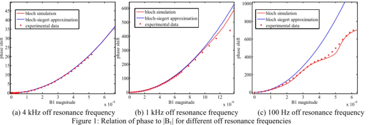
(a) 4 kHz off resonance frequency (b) 1 kHz off resonance frequency (c) 100 Hz off resonance frequency
Figure 1: Relation of phase to |B1| for different off resonance frequencies
1 2 3 4 5 x 10⁻³ -30 -20 -10 0 10 20 30 pulse duration pha se pe rc en t e rror Fermi pulse Hard pulse
Figure 2: Phase percent error between Bloch simulations and Bloch-Siegert approximation for different RF pulse durations
Analysis of B1 mapping by Bloch Siegert Shift
Esra Abaci Turk1,2, Yusuf Ziya Ider1, and Ergin Atalar1,2
1Electrical and Electronics Engineering Department, Bilkent University, Ankara, Turkey, 2UMRAM, Bilkent University, Ankara, Turkey INTRODUCTION
The Bloch-Siegert shift is a new phase-based B1 mapping method [1]. This method utilizes the fact that for a large off-resonance frequency, square of the B1 field
magnitude is proportional to the phase. In this study, relation between the off-resonance frequency, the RF pulse shape, and the duration of the RF pulse is investigated. Moreover, importance of the crusher usage in the sequence is examined for the Fermi and hard pulse shapes. Understanding of these parameters can be helpful for the general use of this method and may give an intuition for appropriate RF pulse design.
THEORY
The main parameters of B1 mapping by the Bloch-Siegert shift method are the off-resonance RF pulse shape, frequency and the pulse duration. In order to obtain a
Bloch-Sigert shift effect, which is quantified by the approximation
∫
Δ = RF dt B ω γ φ 2 2 1 2
, the off-resonance frequency must be large (i.e. forΔωRF>>γB1) [1]. An
analysis of the Bloch equations reveals that even with large frequency offsets, high errors may be observed if the duration of the RF pulse is short. For a hard
pulse, the error between the Bloch-Sigert approximation and the actual phase can be formulated as sinc(ΔωRFt). Therefore, in order to reduce the error to below
10%, one must use a minimum pulse duration of 4π/ωRF.
Another problem with the method is that the magnetization outside of the region of interest may tilt with the off-resonance pulse and corrupt the image and its phase. This problem can be mitigated using crusher gradients.
EXPERIMENTS & RESULTS
All experiments were performed using a 3 tesla Siemens Tim Trio scanner with a Siemens phantom. The imaging parameters were: slice thickness=5mm, FOV=200mm, TR=100ms and resolution=256x256. Body coil was used for the RF transmission and head coil was used for the reception.
In Figure 1, the relation between the
phase and the B1 magnitude is given
for a hard pulse with 4 kHz, 1 kHz and 100 Hz off resonance frequencies. Due to the high off- resonance frequency approximation, in order to obtain high flip angle maps, higher off-resonance frequency is required as shown in the graphs. Figure 2 shows the error between phases obtained by the Bloch simulations and the Bloch-Siegert approximations for the Fermi and hard RF pulses with 4 kHz off resonance frequency. The error is in the form of a ripple and it is less with the Fermi pulse for pulses longer than 1ms.
In Figure 3, applied sequences with and without crusher are shown. Crusher gradients were used to suppress unwanted signals due to the off resonance RF pulses. To analyze the differences between the pulse shapes, SAR limits of the Fermi and hard pulses were adjusted to give same amount of phase shifts. For these experiments, off resonance frequency was 4 kHz and pulse duration was fixed to 8 ms. In order to find the phase shift only due to the B1 field, difference of two phase images obtained with positive and negative off resonance frequencies were used. Figures 4 and 5 show the phase shift images for Fermi and hard pulses. The phase shift obtained with a Fermi pulse with a sequence including crushers is taken as the reference image and the phase difference between this image and the others along the red line are compared in Figure 6. This comparison clearly shows that the effect of the echo due to the out of slice magnetization is high enough to affect the phase shift for hard pulse when there is no crusher. Another point of view is that off-resonance RF pulse may tilt the magnetization outside of the region of interest and this corrupts the image. In order to analyze this effect, for a fixed phase and pulse duration, off resonance frequencies of the Fermi and hard pulses are adjusted to a value which tilts the undesired magnetization up to 1%. For example, for 1 radian phase shift and 8ms pulse duration, for Fermi pulse minimum off-resonance
frequency is 1.5 kHz, however for a hard pulse minimum off-resonance frequency is bigger than 1.5 MHz. It shows that hard pulse cannot be used without crushers.
CONCLUSION:
In this study, B1 mapping by the Bloch-Siegert shift is analyzed with simulations and experiments. It is shown that a minimum amount of duration of the off-resonance pulse is necessary for an
accurate B1 mapping and also crusher gradients have to be used in
order to remove the echo originating from tilting off-slice spins by the off-resonance pulse.
REFERENCE:
[1] Laura I. Sacolick, Florian Wiesinger, Ileana Hancu, and Mika
W. Vogel, “B1 Mapping by Bloch-Siegert Shift,” Magn Reson
Med, 2010;63:1315–1322.
(a) without crushers (b) with crushers
Figure 3: Pulse Sequence for B1 mapping by Bloch- Siegert shift RF Gz Gy Gx RF Gz Gy Gx
Figure 6: Phase difference between the images obtained with the Fermi and the hard pulses for a constant phase shift.
50 100 150 200 -1 -0.5 0 0.5 1 1.5 pixels ph as e d if fer en ce
hard pulse without crusher -fermi pulses with crusher fermi pulse with crusher-without crusher hard pulse with crusher- fermi pulse with crusher
(a) without crushers
(a) without crushers
(b) with crushers
(b) with crushers Figure 4: Phase shift for a Fermi pulse.
Figure 5: Phase shift for a hard pulse
-1 0 1 -1 0 1