Mechanically Controlled Liesegang
Pattern Formation in Stretchable
Polyacrylamide Gels for Elastic
Deformation Tracking
A THESIS SUBMITTED TO
THE GRADUATE SCHOOL OF ENGINEERING AND
SCIENCE
OF BILKENT UNIVERSITY
IN PARTIAL FULFILLMENT OF THE REQUIREMENTS
FOR
THE DEGREE OF
MASTER OF SCIENCE
IN CHEMISTRY
By
Mohammad Morsali
July 2019
Mechanically Controlled Liesegang
Pattern Formation in Stretchable
Polyacrylamide Gels for Elastic
Deformation Tracking
By Mohammad Morsali
July 2019
We certify that we have read thesis and that in our opinion it is fully
adequate, in scope and in quality, as a thesis for the degree of Master of
Science.
____________________
Bilge BAYTEKIN (Advisor)
_____________________
Ferdi KARADAŞ
_____________________
Istvan LAGZI
_____________________
Salih ÖZÇUBUKÇU
_____________________
Emrah ÖZENSOY
Approved for the Graduate School of Engineering and Science:
_______________________
Ezhan KARAŞAN
iii
ABSTRACT
Mechanically Controlled Liesegang Pattern Formation in Stretchable
Polyacrylamide Gels for Elastic Deformation Tracking
Mohammad Morsali
M.S. in Chemistry
Advisor: Bilge BAYTEKIN
July 2019
Pattern formation in nature has been intellectually appealing for many scientists since antiquity. Simultaneous diffusion and reaction of chemicals in gel media may lead to precipitation and complex pattern formation through self-assembly. Periodic precipitations patterns, also known as Liesegang patterns (LP), are one of the stimulating examples of such self-assembling reaction-diffusion systems. So far, it was shown that LP’s periodic band structure and their unique geometry can be controlled by controlling the reaction parameters (e.g. concentration of the reactants) and affecting the reaction medium (e.g. external electrical field). However, so far, the research on LPs have been concentrated mostly around how these patterns are forming, to retrieve information to build a universal mathematical model for them. Although there are studies showing the effect of external fields on the development of these patterns, to the best of our knowledge, so far, there is no example of these systems, used to retrieve information about the changes in the environment as they form. Here, we first show the formation of Liesegang rings by a diffusion-precipitation reaction in a stretchable hydrogel. Then, we present how to use these patterns to ‘read’ the duration, the extent, and the direction of gel deformation. Also, we describe deviations from LP behavior for the patterns (spacing that can be mathematically defined by a geometrical series) formed after the unloading. We believe this first display of such an ‘environmental sensing’ to be a starting point for more investigations on many aesthetically appealing and mathematically challenging self-assembled systems, which have been studied for decades.
iv
ÖZET
Esneyebilen Poliakrilamid Jellerde Elastik Deformasyonun Takip
Edilmesi Icin Mekanik Kontrollu Liesegang Halkalari Oluşumu
Mohammad Morsali
Kimya, Yüksek Lisans
Tez danışmanı: Bilge Baytekin
Temmuz 2019
Doğadaki desen oluşumu, antik çağlardan beri birçok bilim insanının ilgisini çekmiştir. Kimyasalların eş zamanlı difüzyon ve jel ortamında reaksiyona girmesi ve kendiliğinden bir araya gelmesi çökelmeye ve karmaşık desen oluşumunu sağlayabilir. Liesegang halkaları (LH) olarak da bilinen periyodik çökelme desenleri, bu tür kendiliğinden oluşan reaksiyon difüzyon sistemlerinin dikkat çekici örneklerinden biridir. Şimdiye kadar, LH’nin periyodik bant yapısının ve kendine özgü geometrilerinin, reaksiyon parametrelerini kontrol ederek (örneğin, tepkiyen konsantrasyonu) ve tepkime ortamının (örneğin, harici elektrik alanı) özelliklerini değiştirerek kontrol edilebildiği gösterilmiştir. Bununla birlikte, şu ana kadar LH'ler üzerindeki araştırmalar -halkalar için evrensel bir matematik model oluşturmak için bilgi edinmek amacıyla- çoğunlukla bu desenlerin nasıl oluştuğu üzerine yoğunlaşmıştır. Her ne kadar dış etki alanların bu halkaların büyümesine etkisini gösteren çalışmalar olsa da, şu ana kadar literatürde bu sistemlerde halkaların oluştuğu çevrede meydana gelen değişiklikler hakkında bilgi almak için LH’leri kullanan hiçbir örnek yoktur.
Bu çalışmada, ilk defa esneyebilen bir hidrojelde difüzyon-çökelme reaksiyonu ile Liesegang halkalarının oluşumunu göstermekteyiz. Ardından, bu desenlerin jel deformasyonunun süresini, kapsamını ve yönünü gözlemlemek için nasıl kullanılacağını açıklamaktayız. Ayrıca, mekanik gerilmenin ortadan kaldırılmasından sonra oluşan desenlerin (geometrik bir seri ile matematiksel olarak tanımlanabilen aralık) LH davranışından sapmalarını ortaya koymaktayız. Böyle bir “çevresel algılama” nın ilk kez ortaya konmasının, onlarca yıldır incelenen, estetik açıdan çekici
v
ve matematiksel olarak açıklanması zor olan bu sistemler hakkında daha fazla araştırma için bir başlangıç noktası olduğuna inanmaktayız.
Anahtar Kelimler : Liesegang halkaları, sonradan oluşan halkalar, hidrojel, elastik
vi
ACKNOWLEDGMENT
First of all, I would like to express my sincere gratitude to my supervisor Assoc. Prof. Bilge Baytekin for all of her support, guidance, patience and great supervision during this research. I also want to thank Assoc. Prof. Tarik Baytekin for his feedback and support.
I am grateful to Assoc. Prof. Istvan Lagzi for his valuable support and guidance during this research and being a great host during my research visit at Budapest University of Technology and Economics.
Special thanks to all of my colleagues and friends, Rahym Ashirov, Doruk Cezan and Turab Ali Khan for their help and assisting me in experiments. I would like to thank Mertcan Ozel for his help, friendship and support during my stay at Bilkent University. Many thanks to Dr. Joanna Kwiczak Yigitbasi, Dr. Fatma Demir, Mine Demir for being supportive colleagues and great friends.
vii
To Bilge Baytekin
The real wonder woman
viii
TABLE OF CONTENTS
1. INTRODUCTION ... 1
1.1. Chemistry and mathematics of LPs... 4
1.2. The internal and external factors effecting the formation of LPs ... 7
1.3. Hydrogel media mechanically and chemically appropriate for the formation of LP patterns and the simultaneous application of the mechanical input upon LP formation ... 8
1.4. Preliminary work on the LP formation in stretchable hydrogels ... 9
1.5. The ‘post-pattern’ phenomenon ... 13
2. MATERIALS AND METHODS ... 14
2.1. Materials ... 14
2.2. Preparation of polyacrylamide (PAA) hydrogels with primarily-added K2CrO4 content ... 15
2.3. Preparation of polyacrylamide (PAA) hydrogels with secondarily-added potassium chromate content ... 16
2.4. Preparation of 3D polyacrylamide-sodium alginate hybrid hydrogel ... 17
2.5. Preparation of the 3D agarose gels... 17
2.6. Preparation of the agarose stamp ... 18
2.7. Preparation of the Ecoflex substrate ... 18
2.8. The experimental setup for mechanical deformation in 1D and 2D gels ... 19
2.9. Chemical erasing of the LPs formed in the hydrogels ... 20
2.10. Polymerization of pyrrole on LP patterns ... 20
ix
2.12. Image processing and analysis ... 20
3. RESULTS AND DISCUSSION ... 22
3.1. Formation of post-patterns in 1D, 2D, and 3D PAA hydrogels ... 22
3.1.1 Formation of post-patterns in 2D PAA hydrogels ... 22
3.1.2 Formation of post-patterns in 1D PAA hydrogels ... 28
3.1.3 Formation of LP and post-patterns in 3D hydrogels ... 34
3.1.3.1 Formation of post-patterns in 3D agarose gels ... 34
3.1.3.2 Formation of LP and post-patterns in 3D polyacrylamide-alginate hybrid gels ... 36
3.2. Elastic Deformation Tracking in 1D, 2D, and 3D hydrogels by using precipitation patterns ... 40
3.2.1 Determination of the tensile strain in an elastically deformed 2D hydrogel using post-patterns ... 40
3.2.2 Precipitation patterns in an elastically deformed 2D hydrogel under cyclic load ... 41
3.2.3 Precipitation patterns in an elastically deformed 1D hydrogel under cyclic load ... 45
3.3. Removing patterns ... 48
3.4. Pyrrole polymerization on the previously formed precipitation patterns... 48
4. CONCLUSION ... 51
x
LIST OF TABLES
Table 1. The transition times used to yield different cycles of elastic deformation to obtain the precipitation patterns shown in Figure 20. Tend =12 hours (fixed). ... 43
xi
LIST OF FIGURES
Figure 1. Examples of Liesegang patterns. (a) Periodic pattern formation in a volcanic rock [9], reprinted with permission from [10]. (b) The formation of 2D LPs in the polyacrylamide hydrogel presented in this work. (c) Generic mathematical equations governing LPs. The pattern in (b); Inner electrolyte (chromate ion) = 0.01 M, outer
electrolyte (copper (II) ion) = 1 M, acrylamide = 13.5 w%, BIS = 0.056 w%, KPS = 0.187 w%, TEMED = 0.0001 w%. T = 20 °C. For details, please see chapter 2. ... 1
Figure 2. Scheme of a reaction-diffusion system formed by wet stamping in a hydrogel resulting in formation of LPs [11]. (a) Diffusion of outer electrolyte, A, (with a higher concentration than the inner electrolyte) in the hydrogel media doped with inner electrolyte, B. (b) Tentative concentration profiles of outer (B) and inner electrolytes (A) and precipitations formed in LP system (A diffuses from ‘left to right’). (c) Close-up photos of the time lapse of LP formation in the polyacrylamide hydrogel. Inner
electrolyte (chromate ion) = 0.01 M, outer electrolyte (copper (II) ion) = 1 M, acrylamide = 13.5 w%, BIS = 0.056 w%, KPS = 0.187 w%, TEMED = 0.0001 w%. T = 20 °C. For details, please see chapter 2... 3
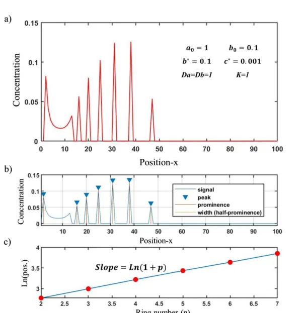
Figure 3. Simulation of Liesegang patterns in 1D using partial differential equations (PDEs) described in ((1-1)~(1-4)) as dimensionless models using a self-developed code in MATLAB by spatial discretization technique using ode45 ODE solver . (a) Formation of sharp periodic precipitations using the qualitative dimensionless model. (b) Peak analysis of the simulated precipitation by identifying the peak positions. (c) Spacing law validation in the model. According to the ‘spacing law’ for LPs, the consecutive peaks positions (𝑋𝑛) and peaks number (n) should follow the equation 𝐿𝑛(𝑋𝑛)/𝑛 = 𝐿𝑛(1 + 𝑝) – as shown in (c) this model successfully predicts/reproduces such a case. ... 6
xii
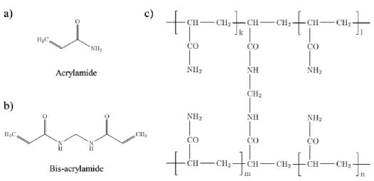
Figure 4. Chemical structure of polyacrylamide hydrogel. (a) Acrylamide monomer (AA) chemical structure. (b) N,N-Methylenebis(acrylamide) cross-linker (BIS) a.k.a. ‘bis-acrylamide’. (c) Covalently cross-linked polyacrylamide hydrogel (PAA). Adopted from ref. [51]. ... 9 Figure 5. Concentric LP formation in stretched polyacrylamide hydrogel and the change in its geometry (from circle to oval) after unloading and releasing the stress.
Inner electrolyte (chromate ion) = 0.01 M, outer electrolyte (copper (II) ion) = 1 M, acrylamide = 13.5 w%, BIS = 0.056 w%, KPS = 0.187 w%, TEMED = 0.0001 w%. T = 20 °C. ... 10
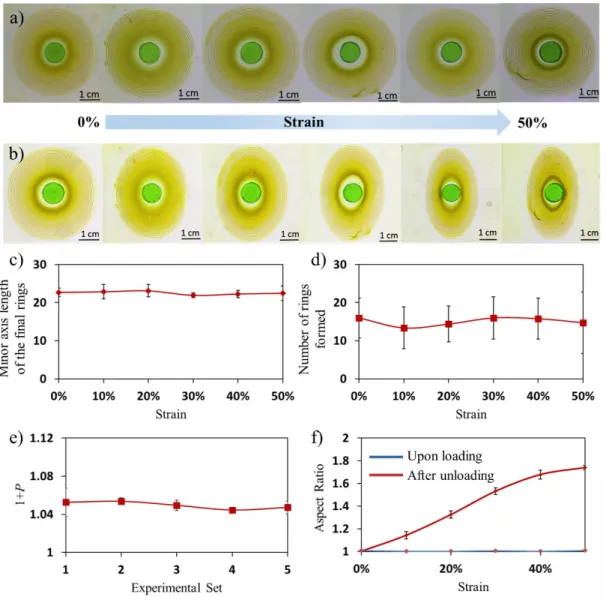
Figure 6. Formation of Liesegang patterns (LPs) upon loading for 24 hrs and just after unloading at the 24th hr. The photos of LPs in gels with 0-50% strain, (a) upon loading for 24 hrs, and (b) just after unloading the stress at the 24th hr. Loading for 24 hours does not affect (c) the minor axis length of the final rings, (d) the estimated number of the rings formed, and (e) spacing coefficient (1+p) in different sets of samples. However, upon unloading LP appearances change significantly as displayed by the (f) changes in the aspect ratio (a) and (b). Inner electrolyte (potassium chromate) = 0.01
M, outer electrolyte (copper chloride) = 1 M, acrylamide = 13.5 w%, BIS = 0.056 w%, KPS = 0.187 w%, TEMED = 0.0001 w%. T = 20 °C. ... 12
Figure 7. Formation of post-patterns in polyacrylamide (PAA) hydrogel with 40% strain upon loading for 24 hrs and unloading for 18 hrs. (photo taken 18 hours after the unloading). Inner electrolyte (potassium chromate) = 0.01 M, outer electrolyte
(copper chloride) = 1 M, acrylamide = 13.5 w%, BIS = 0.056 w%, KPS = 0.187 w%, TEMED = 0.0001 w%. T = 20 °C... 13
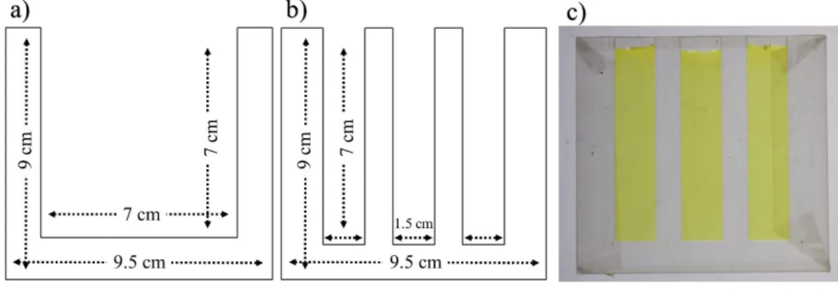
Figure 8. The plexiglass molds dimensions and shapes. (a) Plexiglass mold interior and its dimensions used for casting ‘2D’ rectangular hydrogels. (b) Comb-like plexiglass mold interior and its dimensions for casting three ‘1D’ hydrogels at the same time. (c) The hydrogel casted and formed in ‘1D’ mold with K2CrO4 as inner
electrolyte. Plexiglass thickness = 2 mm. ... 15 Figure 9. Preparation and cast molding of polyacrylamide (PAA) hydrogel. (a) Acrylamide (AA) and Bis-acrylamide (BIS) are dissolved in deionized water. (b) Solution is degassed under vacuum for 20 minutes. (c) KPS and K2CrO4 are added and
mixed carefully to the solution not to introduce further oxygen in the sample. (d) Addition of TEMED and gelation initiation in prepared solution after addition of
xiii
TEMED. (e and f) Casting of solution in plexiglass mold before first gelation stage complete using syrenge. ... 16 Figure 10. Preparation of the 3D polyacrylamide-sodium alginate hybrid hydrogel. (a) Dissolving 0.15 g sodium alginate (SA) in 30 ml deionized water in ice bath. (b) Mixing sodium alginate solution and polyacrylamide (PAA) hydrogel precursors
(8.676 g acrylamide (AA), 0.036 g Bis-acrylamide (BIS), 0.12 g of potassium peroxydisulfate (KPS) and 0.12 g K2CrO4) dissolved in 25.2 ml deionized water. (c)
Addition of 120 µL TEMED as catalyst to start gelation. (d) Pouring solution to polystyrene (PS No. 6) cuboid molds (4 cm × 4 cm × 4 cm)... 17 Figure 11. Schematic illustration of 2D uniaxial stretching setup. (a) Transferring hydrogel on Ecoflex substrate. (b) Loading (stretching) sample, followed by stamp placing at the center of the hydrogel. (c) Formation of the patterns on the hydrogel upon loading. (d) The sample unloading... 19 Figure 12. Gray-value analysis of Liesegang patterns in Figure 13a. (a) Gray-value profile of LPs in loading (stretching) direction just before unloading. (b) Peaks analysis of gray-value profile including peaks intensities, widths (full width at half maximum) and peak prominences (difference between gray-value of bands and their neighbor depletion zone). ... 21 Figure 13. A typical demonstration of PP formation in 2D hydrogel. (a-c) The patterns of CuCrO4 formed by diffusion of Cu2+ into CrO4- containing polyacrylamide (PAA)
gel during and after elastic deformation of the gel. (a) Formation of patterns in a stretched (40% strain) PAA hydrogel after 24 hours. (b) The change in the aspect ratio of patterns after unloading (releasing) the stress. (c) Post-patterns formed in the sample after unloading (release) (photo taken 18 hours after unloading). Inner electrolyte
(potassium chromate) = 0.01 M, outer electrolyte (copper chloride) = 1 M, acrylamide = 13.5 w%, BIS = 0.056 w%, KPS = 0.187 w%, TEMED = 0.0001 w%. T = 20 °C. For details of the gel preparation and loading setup please see Chapter 2. ... 23
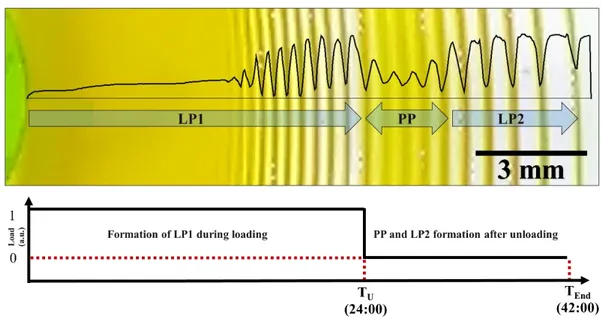
Figure 14. Gray-value profile of the patterns of CuCrO4 formed by diffusion of Cu2+
(1 M) into CrO42- (0.01 M) containing polyacrylamide gel during and after elastic
deformation of the gel (close-up of the patterns in loading (stretching) direction in Figure 13c). During the 24-hour loading, regular LP1 form. Post-pattern (PP) and LP2 regions form after unloading (releasing) the sample (18th hour after unloading). Inner
electrolyte (potassium chromate) = 0.01 M, outer electrolyte (copper chloride) = 1 M, acrylamide = 13.5 w%, BIS = 0.056 w%, KPS = 0.187 w%, TEMED = 0.0001 w%. T
xiv
= 20 °C. 40 % strain upon loading for 24 hrs. Photo taken in 18 hours after unloading. For details of the gel preparation and loading setup please see Chapter 2. ... 24
Figure 15. Differences between the patterns formed after unloading (PP) and the regular LP formed during loading (LP1) and long after unloading (LP2). (a) Gray-value analyses of the patterns of CuCrO4 formed by diffusion of Cu2+ (1 M) into CrO4
-(0.01 M) containing polyacrylamide gel during and after elastic deformation of the gel (data retrieved from the gray-value analysis of the image shown in Figure 14). Changes in (b) the width of patterns, (c) the spacing of the two consecutive bands , (d) the peak prominence (difference between gray-value of bands and their neighbor depletion zone). ... 26 Figure 16. Gray-value profile of precipitation patterns upon loading at the 4th hour and unloading at the 6th hour. Stamp is placed on an unloaded polyacrylamide (PAA) hydrogel. After 4 hours of LP formation, the sample is loaded (stretched) up to 40 % strain. PPs and LP2s are led to develop, then sample is unloaded after 2 hours and the photo is taken after 6 hours. Inner electrolyte (potassium chromate) = 0.01 M, outer
electrolyte (copper chloride) = 1 M, acrylamide = 13.5 w%, BIS = 0.056 w%, KPS = 0.187 w%, TEMED = 0.0001 w%. T = 20 °C. For details of the gel preparation and the loading setup please see Chapter 2. ... 27
Figure 17. value analyses of the PP and LP2 displayed in Figure 16. (a) Gray-value profile. Changes in (b) the width of patterns, (c) the spacing of the two consecutive bands, (d) the peak prominence (difference between gray-value of bands and their neighbor depletion zone). (here, LP1 are not shown since their line spacings are too small to be detected by gray-value analyses))... 28 Figure 18. Schematic illustration of the steps involved in the preparation of the setup for 1D Liesegang pattern formation. (a) Placing polyacrylamide (PAA) hydrogel on Ecoflex substrate. (b) Loading and stretching PAA hydrogel. (c) Placing cuboid stamp at the center of the PAA hydrogel. (d) 1D Liesegang patterns forms as parallel bands. Note that the length of the stamp should be the same as the hydrogel width to obtain these parallel precipitation patterns. ... 29 Figure 19. The formation of precipitation patterns in 1D gels, the effect of uniaxial, tensile elastic deformation on the pattern formation in the polyacrylamide (PAA) gel. (a) Formation of LPs in Agarose (Agarose, 8 w%). (b) LPs formed in a reference (unloaded) PAA hydrogel (acrylamide = 13.5 w%, BIS = 0.056 w%, KPS = 0.187 w%,
xv
strain) PAA sample after 12 hours. (d) ‘Shrinking’ of LPs in the reverse direction of the previous tension in the PAA just after unloading. (e) Formation of PPs and LP2s in PAA hydrogel after unloading, in 12 hours. (f-g) Gray-value profiles of LPs developed in the reference and the loaded PAA gel after 12 hours of loading. In both
Agarose and PAA hydrogels: Inner electrolyte (potassium chromate) = 0.01 M, outer electrolyte (copper chloride) = 1 M. For details of the gel preparation and the loading setup please see Chapter 2. ... 30
Figure 20. Demonstration of the stretching and the compressing functions. Elastic mechanical deformation can be explained mathematically using so called stretching and compressing functions. If f(x) represent (red) concentration profile in a medium, f(0.5x) represents (yellow) the concentration profile in the case of ‘shrinkage’ with -50% strain (can be analogue to stretched/released transformation) and f(2x) shows (blue) concentration profile upon stretching the sample with 50% strain (unstretched/stretched transition). ... 32 Figure 21. The formation of PP in 1D polyacrylamide (PAA) gels loaded to 10-50% strain. LP formed during 12 hours of loading; after unloading, 12 hours of waiting generates PP and LP2. Inner electrolyte (potassium chromate) = 0.01 M, outer
electrolyte (copper chloride) = 1 M, acrylamide = 13.5 w%, BIS = 0.056 w%, KPS = 0.187 w%, TEMED = 0.0001 w%. T = 20 °C. For details of the gel preparation and loading setup please see Chapter 2. ... 33
Figure 22. Time evolution of the precipitation patterns in a 1D PAA gel with LP1s already developed (Figure 21d). LP formed for 12 hours and the consecutive photos are showing time evolution of pattern formation (PPs and LPs) after unloading the stress. The patterns were developed for further 8 hours, images were taken every 30 minutes. For details of the gel preparation and loading setup please see Chapter 2. ... 33 Figure 23. Formation of precipitation patterns in 3D in 8 w% agarose sphere. (a) Agarose sphere removed from 1 M K2CrO4 outer electrolyte solution. (b) Cross
section of 3D sample. (c) Thin layer cut from sample for rings detection. Inner
electrolyte (copper chloride) = 0.01 M, outer electrolyte (potassium chromate) = 1 M, T=20 °C. For details of the gel preparation please see Chapter 2. ... 34
Figure 24. The formation of 3D patterns in an agarose hydrogel hemisphere (diameter = 4 cm) using wet stamping method. (a) Patterns formed after 24 hours. (b) Top view of sample without stamp. (c) Cross section of sample after cutting to halves. (d) Thin
xvi
film cut of cross section for rings detection. Inner electrolyte (potassium chromate) =
0.01 M, outer electrolyte (copper chloride) = 1 M. T = 20 °C. For details of the gel preparation please see Chapter 2. ... 35
Figure 25. Cracks formed in presence of 20% mechanical deformation (compression) in cubic agarose sample (a). Thin layers of sample for rings detection (b). Agarose =
8 w%, Inner electrolyte (potassium chromate) = 0.01 M, outer electrolyte (copper chloride) = 1 M, T = 20 °C. For details of the gel preparation and loading setup please see Chapter 2. ... 36
Figure 26. Effect of mold surface modification on final 3D polyacrylamide-sodium alginate (PAA-SA) hybrid hydrogel. (a) PAA-SA, gel molded without filter paper. (b) PAA-SA hydrogels molded with filter paper. In (b) demolding is easy for both samples but in the sample with dry filter paper, separation of the gel and the filter paper is not possible. Finally, the best configuration is using CaCl2, for which both demolding and
removal of the paper are straightforward. Inner electrolyte (potassium chromate) =
0.01 M, acrylamide = 13.5 w%, BIS = 0.056 w%, KPS = 0.187 w%, sodium alginate = 0.187 w%, TEMED = 0.0001 w%. T = 20 °C. For details of the gel preparation please see Chapter 2. ... 37
Figure 27. Formation of LP in the 3D polyacrylamide-sodium alginate (PAA-SA) hybrid hydrogel. The cylindrical stamp is place on the surface of the cube-shaped gel. Developing time was 24 hrs. The chemistry and the concentration of inner and outer-electrolyte are similar to 1D and 2D PAA hydrogels. Inner outer-electrolyte (potassium
chromate) = 0.01 M, acrylamide = 13.5 w%, BIS = 0.056 w%, KPS = 0.187 w%, sodium alginate = 0.187 w%, TEMED = 0.0001 w%. T = 20 °C. For details of the gel preparation please see Chapter 2. ... 38
Figure 28. Mechanical deformation setup in 3D. (a) 3D polyacrylamide-sodium alginate (PAA-SA) hydrogel. (b) Isometric view of compression test setup. (c) Top view of compressed gel with stamp placed. Compression = 30 %. Inner electrolyte
(potassium chromate) = 0.01 M, outer electrolyte (copper chloride) = 1 M, acrylamide = 13.5 w%, BIS = 0.056 w%, KPS = 0.187 w%, sodium alginate = 0.187 w%, TEMED = 0.0001 w%. T = 20 °C. For details of the gel preparation and the loading setup please see Chapter 2. ... 38
Figure 29. formation of patterns in 3D polyacrylamide-sodium alginate (PAA-SA) gel after 24 hours with 30% compression. Concentric shell patterns form, (a) top, (b) side
xvii
and (c) bottom view of the hemispherical patterns. For details of the gel preparation
and loading setup please see Chapter 2. ... 39
Figure 30. Photos of the LP formed upon loading and just after unloading (releasing) the compressive load. (a) Top view of pattern formed in polyacrylamide-sodium alginate (PAA-SA) 3D hydrogel in 24 hours under a compressive load. (b) Aspect ratio of the pattern increases (from 1.0 to 1.30) in 3D LP pattern right after unloading.
For details of the gel preparation and loading setup please see Chapter 2. ... 39
Figure 31. Formation of post-patterns in 3D in the presence of mechanical deformation (30% compression). (a) LP patterns just after releasing the load. (b) Formation of post rings perpendicular to the stress direction, bottom view. (c) Side view of patterns perpendicular to the stress direction. (d) Side view of patterns in the stress direction.
Inner electrolyte (potassium chromate) = 0.01 M, outer electrolyte (copper chloride) = 1 M, acrylamide = 13.5 w%, BIS = 0.056 w%, KPS = 0.187 w%, sodium alginate = 0.187 w%, TEMED = 0.0001 w%. T = 20 °C. For details of the gel preparation and loading setup please see Chapter 2. ... 40
Figure 32. Post-pattern (PP) formation in the polyacrylamide (PAA) samples with applied uniaxial strain. (a) The change in the aspect ratios of the concentric LP1 formed for 24 hrs, photo taken just after unloading. (b) The formation of the PPs and LP2s (in 18 hours of waiting time) after unloading. (c) The effect of strain on the PP region’s size and on the precipitation bands’ width and contrast. Inner electrolyte
(potassium chromate) = 0.01 M, outer electrolyte (copper chloride) = 1 M, acrylamide = 13.5 w%, BIS = 0.056 w%, KPS = 0.187 w%, TEMED = 0.0001 w%. T = 20 °C. For details of the gel preparation and loading setup please see Chapter 2. ... 41
Figure 33. Pattern formation under cyclic loading. An example of a 3 step-cyclic elastic deformation of the PAA gel and the formation of the precipitation patterns. Formation of patterns in a) 4 hrs of unloaded gel, followed by b) a stretching, which causes an overall pattern shown in (c) after 4 hrs of loading. The sample is then unloaded as shown in (d) and the patterns were left to develop for 4 hrs more in the unloaded state to yield the pattern in (e). (Here the photos are given in gray scale for a better contrast.) Inner electrolyte (potassium chromate) = 0.01 M, outer electrolyte
(copper chloride) = 1 M, acrylamide = 13.5 w%, BIS = 0.056 w%, KPS = 0.187 w%, TEMED = 0.0001 w%. T = 20 °C. For details of the gel preparation and loading setup please see Chapter 2. ... 42
xviii
Figure 34. Cyclic deformation in 2D polyacrylamide (PAA) hydrogels. Samples are mechanically loaded/unloaded (stretched/released) in x-direction through cycles as shown in (a); Vertical axis 0 = unloaded (released/unstretched), and 1 = loaded (stretched) sample. (b) Overall patterns formed during the corresponding loading cycles. (c) A magnification of the patterns formed in cyclic loading and unloading (x-direction). (d) Peak analysis of the PP formed, including peak width and prominence analysis of PP (e) PP formation in y-direction (perpendicular to uniaxial loading) (The photos are given in gray-scale for better contrast). Inner electrolyte (potassium
chromate) = 0.01 M, outer electrolyte (copper chloride) = 1 M, acrylamide = 13.5 w%, BIS = 0.056 w%, KPS = 0.187 w%, TEMED = 0.0001 w%. T = 20 °C. For details of the gel preparation and the loading setup please see Chapter 2. ... 44
Figure 35. Cyclic deformation in 1D polyacrylamide (PAA) hydrogels. Samples are mechanically loaded/unloaded (stretched/released) in x-direction through cycles as shown in (a); Vertical axis 0 = unloaded (released/unstretched), and 1 = loaded (stretched) sample. (b) The patterns formed in cyclic loading and unloading (x-direction). Inner electrolyte (potassium chromate) = 0.01 M, outer electrolyte (copper
chloride) = 1 M, acrylamide = 13.5 w%, BIS = 0.056 w%, KPS = 0.187 w%, TEMED = 0.0001 w%. T = 20 °C. For details of the gel preparation and loading setup please see Chapter 2. ... 46
Figure 36. A detailed demonstration of the PP formation in cyclic loading and unloading. (a) Magnified view of the patterns shown in Figure 35. (b) Peak prominence and (c) peak width analysis of the patterns. Inner electrolyte (potassium
chromate) = 0.01 M, outer electrolyte (copper chloride) = 1 M, acrylamide = 13.5 w%, BIS = 0.056 w%, KPS = 0.187 w%, TEMED = 0.0001 w%. T = 20 °C. For details of the gel preparation and loading setup please see Chapter 2. ... 47
Figure 37. Polymerization of pyrrole on polyacrylamide (PAA) hydrogel with LPs formed. (a-b) Polypyrrole formation on regular LPs. (c-d) Polypyrrole formation on the patterns developed on mechanically deformed hydrogel. Peak analysis of LP formed on PAA (e) without mechanical deformation, and (f) with mechanical deformation. In all cases, the samples with patterns were dipped in pyrrole solution (pyrrole =0.1 M, HCl = 0.1 mM). Inner electrolyte (potassium chromate) = 0.01 M,
outer electrolyte (copper chloride) = 1 M, acrylamide = 13.5 w%, BIS = 0.056 w%, KPS = 0.187 w%, TEMED = 0.0001 w%. T = 20 °C. For details of the gel preparation please see Chapter 2. ... 49
xx
LIST OF ABBREVIATIONS
LP Liesegang pattern PP Post-pattern PAA Polyacrylamide SA Sodium alginate AA Acrylamide BIS N,N’-methylene(bis)acrylamide KPS Potassium peroxydisulfate TEMED N,N,N′,N′-tetramethylethylenediamine LU Loading/unloading UL Unloading/loading1
CHAPTER 1
1. INTRODUCTION
Self-assembly has been a topic of interest among researchers as it provides autonomous organization of components in a system without external manipulation of individual components in detail [1]. There are few self-assembling and pattern evolving systems as a result of the processes, which would be expected to bring more homogeneity rather than a periodic heterogeneous state [2]. Liesegang patterns (LPs) are one of the examples of spontaneous pattern formation [3], formed by reaction-diffusion (reaction-diffusion coupled to the reaction of chemicals), which leads to the periodic bands of precipitation [4] (Figure 1). These periodic structures follow specific mathematical laws [5] including time law [6], spacing law [7], and width law [8] which make them unique and distinguishable from other periodic pattern forming phenomena.
Figure 1. Examples of Liesegang patterns. (a) Periodic pattern formation in a volcanic rock [9], reprinted with permission from [10]. (b) The formation of 2D LPs in the polyacrylamide hydrogel presented in this work. (c) Generic mathematical equations governing LPs. The pattern in (b); Inner electrolyte (chromate ion) = 0.01 M, outer
2
electrolyte (copper (II) ion) = 1 M, acrylamide = 13.5 w%, BIS = 0.056 w%, KPS = 0.187 w%, TEMED = 0.0001 w%. T = 20 °C. For details, please see chapter 2.
Hydrogels have been chosen as reaction medium to monitor the formation of reaction-diffusion patterns in many literature examples, since they provide a necessary medium for the diffusion of the system components, minimize the convection, and provide a stable environment for the retention of the formed pattern. To form a Liesegang pattern, in addition to a hydrogel medium, two inter diffusing components (called as electrolytes) which can react to form a precipitate are necessary. In Figure 2, we describe a system, in which the formation of the LP is done in a virtually 2D
(planar) fashion (Figure 2). In this system, the length of the third dimension of the gel
(the height) is much smaller than the other two, so the patterns can be visualized from the ‘top’, as if they are forming in a plane. Conventionally, wet stamping method is used to bring the two reactants together in such a ‘2D’ system for a systematic and clear monitoring of the event and the effect of some experimental parameters on it, i.e. the concentration of the reactants. The reactant, which is supplied from outside (through another gel called as ‘stamp’) into gel medium is known as the outer
electrolyte and the reactant, which is doped homogeneously in the gel medium is
known as the inner electrolyte [11], Figure 2. For a reaction-diffusion system to produce LPs, there should be large difference (10 to 100 times) between the concentration of inner and outer electrolytes. Putting the stamp soaked with the outer electrolyte (A) on the hydrogel previously doped with inner electrolyte (B) (Figure 2a), will lead to the diffusion of A into the hydrogel media. In the classic theory of this phenomenon [12] as A diffuses into the gel, its concentration rises in the medium. Simultaneously, A reacts with B, forming the water-insoluble reaction product, P. The amount of the product increases as the reaction proceeds and reaches a threshold necessary for the precipitation. At this point, P precipitates. The interplay between the diffusion (continuously carrying more A into the hydrogel) and the reaction between
B and A, forming product P that depletes A and B concentrations, leads to changes in
the concentration gradients of A and B in hydrogel media. As a result, such a reaction-diffusion system leads to a periodic structure, in which the ‘circles’ or ‘bands’ are the places, where P forms in the highest amounts (Figure 2b).
3
Figure 2. Scheme of a reaction-diffusion system formed by wet stamping in a hydrogel resulting in formation of LPs [11]. (a) Diffusion of outer electrolyte, A, (with a higher concentration than the inner electrolyte) in the hydrogel media doped with inner electrolyte, B. (b) Tentative concentration profiles of outer (B) and inner electrolytes (A) and precipitations formed in LP system (A diffuses from ‘left to right’). (c) Close-up photos of the time lapse of LP formation in the polyacrylamide hydrogel. Inner
electrolyte (chromate ion) = 0.01 M, outer electrolyte (copper (II) ion) = 1 M, acrylamide = 13.5 w%, BIS = 0.056 w%, KPS = 0.187 w%, TEMED = 0.0001 w%. T = 20 °C. For details, please see chapter 2.
LPs can be encountered frequently in nature [13–15]. Their aesthetical beauty and complex nature attracted the attention of many scientists. Since their discovery [16], they have been proposed for many applications [15] like sensors, colloidal and surface sciences, bioengineering and microfluidics, and fabrication of microstructure materials alongside other pattern formation techniques [17]. However, so far no ‘real’ application of such LPs has been truly realized. LPs can be observed in different geometries of the hydrogels than the ‘2D’ [11] described above. Formation of LPs in different hydrogels and with other electrolytes in ‘1D’ (in vertical test tubes) by simple solution diffusion [18,19], and in 3D are described in the literature [20]. LPs were also reported to form in systems in water vapor [21], and also in the absence of water [22],
4
which endowed the belief that many reaction-diffusion systems can be engineered to form periodic precipitation [23].
1.1. Chemistry and mathematics of LPs
Chemical systems that form unusual visual patterns has always been at the center of attention of scientists and mathematicians. For example, Alan Turing, one the greatest mathematicians of all times, tried to formulate many pattern-forming system in nature [24] and the temporal evolution of patterns. LPs, with their characteristic spacing, width, and time laws, are different than Turing patterns and are formed by other chemical mechanisms [25]. Generally, models describing formation of LPs can be classified into two; pre-nucleation and post-nucleation [26]. In the pre-nucleation model, pattern formation is the result of a perturbation of the diffusion by nucleation. Nucleation takes place, when the system becomes supersaturated and reaches a critical point, at which the system in a far-from equilibrium state transforms to its equilibrium state [27]. In the post-nucleation model, the precipitation region is the result of competitive growth of precipitate and ends in a phase separation and an uneven distribution of the precipitate [4,26,28]. In post-nucleation model, it is not necessary for nucleation and precipitation to occur at the same time and location. Nucleation will result in the formation of homogenously distributed sol of colloidal particles. Ostwald ripening occurs and larger particles grow while smaller particles get eliminated [12,29,30]. Although the two models proposed are mechanistically different, their mathematical descriptions are essentially similar [31]. In both models, the diffusion term can be expressed using Fick’s second law and the reaction can be described either in the form of a mass action law, or a phase separation driven by Cahn-Hilliard or Gibbs-Thomson effect [26].
A simple chemical mechanism [32] is based on the pre-nucleation and supersaturation theory, which describes the production of precipitates through a two-step mechanism incorporating an intermediate species. This mechanism can be written as:
𝐴 + 𝐵 → 𝐶 𝐶 → 𝑃
where A and B are outer and inner electrolytes, and C is the intermediate product, which can transform to precipitate P. Usually, the initial condition is such that the
5
concentration of the outer electrolyte (A) is much higher than that of the inner electrolyte (B); thus, the pattern formation is governed by the diffusion front of the outer electrolyte. In this model, C forms continuously behind the chemical front as a result of mass action law (1-3), and C can transform to immobile precipitate, P, if the local concentration of C reaches a nucleation threshold. The precipitate can grow further by further deposition of P at this point. This precipitation process is much faster than the diffusion of the chemical species; therefore, the distinct LP bands can form. These processes can be written in the form of a set of partial differential equations, which describe the evolution of the patterns.
𝜕𝑎 𝜕𝑡 = 𝐷𝑎∇𝑥2𝑎 − 𝜕𝑐 𝜕𝑡 − 𝜕𝑝 𝜕𝑡 (1-1) 𝜕𝑏 𝜕𝑡 = 𝐷𝑏∇𝑥2𝑏 − 𝜕𝑐 𝜕𝑡 − 𝜕𝑝 𝜕𝑡 (1-2) 𝜕𝑐 𝜕𝑡 = 𝜃(𝑎. 𝑏 − 𝑎𝑏∗)(1 − 𝜃(𝑝)) × 𝑘. 𝑎. 𝑏 (1-3) 𝜕𝑝 𝜕𝑡 = 𝜃(𝑐 − 𝑐∗) × 𝑘. 𝑎. 𝑏 (1-4)
where a, b, c and p are concentration of inner electrolyte (A), outer electrolyte (B), intermediate product (C) and final precipitation formed (P), respectively. Da and Db
show diffusion coefficient of A and B, and 𝜽 is the Heaviside function. ab* is the
thermodynamic threshold for formation of precipitate. c* is the nucleation threshold,
which is in the form of a.b; however with higher value and include the kinetics in precipitation phenomenon [33]. Using these equations in a self-developed MATLAB® code by spatial discretization and implementing ode45 ODE solver (designed for solving ordinary differential equations), we tried to qualitatively simulate the appearance of ‘1D’ LP lines. As shown in Figure 3, this mathematical model can reproduce the LP with corresponding line spacings and spacing coefficients. The periodic peaks plotted by the program obey the spacing law observed experimentally, that is the set of consecutive peak position obey 𝑋𝑛+1/𝑋𝑛 = 1 + 𝑝 relation (𝐿𝑛(𝑋𝑛)/𝑛 = 𝐿𝑛(1 + 𝑝)) when the pattern is completed. Note that, this model is not
6
capable of reproducing ‘the width law’, which can be observed experimentally, so the widths of the peaks displayed in Figure 3 are the size of space grid size (∆x) and fixed in all peaks.
Figure 3. Simulation of Liesegang patterns in 1D using partial differential equations (PDEs) described in ((1-1)~(1-4)) as dimensionless models using a self-developed code in MATLAB by spatial discretization technique using ode45 ODE solver . (a) Formation of sharp periodic precipitations using the qualitative dimensionless model. (b) Peak analysis of the simulated precipitation by identifying the peak positions. (c) Spacing law validation in the model. According to the ‘spacing law’ for LPs, the consecutive peaks positions (𝑋𝑛) and peaks number (n) should follow the equation 𝐿𝑛(𝑋𝑛)/𝑛 = 𝐿𝑛(1 + 𝑝) – as shown in (c) this model successfully predicts/reproduces
7
1.2. The internal and external factors effecting the formation of LPs
Matalon and Packter reported the effect of the concentration of the anions and the cations (the electrolytes), pH, the chemistry of the gel medium on the LP formation. They also reported a special case, in which an addition of chloride ion to a gelatin gel effects the LP formation in this gel [34]. Badr and Sultan described the effect of electrolyte concentrations on morphology of Co(OH)2 LPs [35]. The effect of the gel
precursor concentration and the gel impurities,i.e., the presence of gelatin as impurity in agarose, on the spacing coefficient (1+p) of copper chromate LPs in agarose gel was also reported by Lagzi [32]. Shreif et al. reported a chemical modification for Co(OH)2 LPs, that clears the fuzzy precipitate region tracing at the back of the
propagating pattern, which increases the LP ring spacings. In their study, they display the effect of three main parameters, which alters overall LP appearance: 1) Decreasing the concentration of the diffusing (outer) electrolyte (NH4OH), 2) Applying a constant
radial electric field across the circular pattern, and 3) Increasing the gel concentration to a moderately high value. It is also possible to distort LPs morphology in a 2D system by applying a linear electric field across the gel medium [36]. Toramaru et al. showed that concentration of the gel medium can highly affect the LPs morphology, e.g., in a Liesegang system forming lead iodide precipitate, in low concentrations of the agarose gel, tree-like morphologies can be observed instead of LPs. They also showed that tree- like morphologies can coexist with LPs in the medium concentrations of the gel precursor [37].
Kárpáti-Smidróczki et al. studied the effect of the degree of the crosslinker (glutaraldehyde) on the formation LPs in PVA gels [38]. Smoukov et al. showed the effect of UV-induced crosslinking of a dichromated gelatin via reduction of chromate ions. In this method, the amount of dichromate in inner electrolyte decreases and the gel become stiffer and as a result the heights of the surface undulations decreases [39]. There are other studies on the external control LP formation with electric fields [40– 43] and microwave radiation [44].
Despite the extensive knowledge and numerous reports on internal and external effects on the LP formation as shown above, there is no study on the effect of mechanical deformation of the medium on LP formation. However, it is reasonable to think, an elastic deformation - that does not damage the gel’s initial form upon loading and once the load is released - can be used to effect the formation of LPs. However,
8
for this, the conventional gel media for LP cannot be used, since none of these media, e.g., agarose, gelatin, are stretchable - they disintegrate even at small tensile or compressive loads. Therefore, new, stretchable gels are needed for such an operation. However, despite their emerging applications [45], most ‘stretchable gels’ also have weak mechanical properties and do not show high stretchability, e.g., alginate hydrogel can be stretched up to 20% strain until rupture and gelatin (at a swelling of 40 times) can be extended up to 11% strain to break [45,46]. Still, there are a few synthetic hydrogels including polyacrylamide (PAA), which show desirable mechanical properties with proper elasticity and can be stretched in the range of 10 to 20 times its original dimension (~1000 to 2000 % strain) [45]. Therefore, we used PAA in our experiments as the receiving gel medium, to probe the effect of mechanical deformation of the gel on the formation of the LP patterns.
1.3. Hydrogel media mechanically and chemically appropriate for the formation of LP patterns and the simultaneous application of the mechanical input upon LP formation
The transparent polyacrylamide (PAA) gel enables the visual monitoring of the diffusion of charged species, which diffuse at moderate rates (measured in hours) in the gel, and therefore, has been used as a common electrophoresis medium [47–49]. PAA structure and the factors influencing its properties is well documented in the literature. The ratio of the total weight of monomers to the volume of the solution (%T) and the ratio of the mass of cross-linker to the total mass of monomers (%C) are reported to have significant impact on the swelling capacity and pore size of the gel, [49,50] which eventually affect the mechanical properties of the PAA hydrogel.
9
Figure 4. Chemical structure of polyacrylamide hydrogel. (a) Acrylamide monomer (AA) chemical structure. (b) N,N-Methylenebis(acrylamide) cross-linker (BIS) a.k.a. ‘bis-acrylamide’. (c) Covalently cross-linked polyacrylamide hydrogel (PAA). Adopted from ref. [51].
For a PAA gel to be suitable for a test of our hypothesis, it has to be both highly stretchable and strong . Therefore, the two experimental parameters, the water content (%T) and the cross-linker ratio (%C), had to be optimized, firstly. On the other hand, the addition of inner electrolyte (for forming LPs) to the hydrogel may also alter its stretchability and strength. For example, in our case, the doped PAA hydrogel with an inner electrolyte (chromate ions (0.01 M)), cross-linking and polymerization are hindered, which vitally effects the strength of the gel, due to the formation of hydrogen bonding [52] between chromate’s oxygen atoms and the hydrogens in the amide groups of the gel. In order to overcome this problem and reattain gel integrity, addition of more cross-linker is then required.
%𝑇 =𝑚 𝑎𝑐𝑟𝑦𝑙𝑎𝑚𝑖𝑑𝑒 (𝑔) + 𝑚 𝑐𝑟𝑜𝑠𝑠𝑙𝑖𝑛𝑘𝑒𝑟 (𝑔) 𝑡𝑜𝑡𝑎𝑙 𝑣𝑜𝑙𝑢𝑚𝑒, 𝑚𝑙 × 100 (1-5) %𝐶 = 𝑚 𝑐𝑟𝑜𝑠𝑠𝑙𝑖𝑛𝑘𝑒𝑟 (𝑔) 𝑚 𝑎𝑐𝑟𝑦𝑙𝑎𝑚𝑖𝑑𝑒 (𝑔) + 𝑚 𝑐𝑟𝑜𝑠𝑠𝑙𝑖𝑛𝑘𝑒𝑟 (𝑔)× 100 (1-6)
1.4. Preliminary work on the LP formation in stretchable hydrogels
In a preliminary work from our group [53], the above-mentioned gel parameters to obtain a stretchable and strong gel were optimized, in order to realize our target reaction-diffusion system, in which the gel medium will be subjected to a mechanical
10
input. Then, the most suitable reactions with a chemistry that is orthogonal to the groups present in the structure of the hydrogel reaction medium were determined. In one of the mechanically and chemically optimized systems, a 2D setup of the PAA hydrogel (7 cm x 7 cm x 2 mm) was prepared, doped with K2CrO4 (0.01 M, inner
electrolyte) by addition of K2CrO4 into PAA hydrogel precursors before gelation. The
stamp, which contains 1.0 M of CuCl2 outer electrolyte, was prepared by soaking the
stamp in the corresponding solution for 40 minutes. Then the doped gel was clamped on the stretching setup and the stamp was placed at the center of the PAA hydrogel, as shown in Figure 5. (see Experimental for further details of the hydrogel and the stamp preparation and the stretching setup). The gel was loaded a uniaxial tension to yield an elastic strain of 50%, and was let to stay in the loaded position (under stress)
as long as the LP patterns were developed (24 hrs). (Strains up to 60% were found to
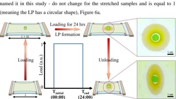
cause only elastic deformation and no plastic deformation in this gel medium) An identically prepared but ‘not loaded’ sample was prepared in parallel, as a control sample. The LPs formed in the loaded (stretched) gel and the not-loaded (not stretched) control are almost identical in their positions relative to the stamp. This was shown to be the case for all the samples loaded to obtain strains of 10% to 50%. In other words, mechanical deformation has no effect on the LP formation on the stretched samples. The ratio of the final ring ‘diameters’(the ratio of the highest (major) axis length to the lowest (minor) axis length, or ‘the aspect ratios’ - as we named it in this study - do not change for the stretched samples and is equal to 1 (meaning the LP has a circular shape), Figure 6a.
Figure 5. Concentric LP formation in stretched polyacrylamide hydrogel and the change in its geometry (from circle to oval) after unloading and releasing the stress.
11
Inner electrolyte (chromate ion) = 0.01 M, outer electrolyte (copper (II) ion) = 1 M, acrylamide = 13.5 w%, BIS = 0.056 w%, KPS = 0.187 w%, TEMED = 0.0001 w%. T = 20 °C.
The fact that same, circular concentric LP were observed and the LPs propagating front (diffusion front) was located at the same position (distance) with respect to the stamp, regardless of the different extent of strain applied on the hydrogel samples tells us that the diffusion phenomenon was not affected by the elastic mechanical input (Figure 6a). This was also verified by the observations that spacing and width laws were all valid for both the loaded and the control (not loaded) samples. Figure 6. (We should note here that ‘the number of the rings’, which has been one of the prominent parameters reported in the literature of LPs, produces high errors due to the difficulty in identifying the exact position and the number of the earlier rings (Figure 6d). Therefore, we used spacing coefficients (1+p), which are 𝑋𝑛+1 𝑋
𝑛
⁄ = 1 + 𝑝, and the aspect ratios of the final pattern for comparison of the LP patterns).
Upon releasing the load (unloading), however, the LPs formed on the stretched samples looked different than the control sample, which was not loaded (Figure 6). The visual difference between the loaded and not-loaded samples - which we expressed as the change in the aspect ratio - is proportional to the extent of strain; as illustrated in Figure 6f. Increasing the strain from 0% to 50%, the aspect ratio increased from 1 up to 1.74. Since the standard deviation of the aspect ratio vs. strain was found to be quite low, this type of information can also be used ‘reversely’; i.e. the aspect ratio of the LP in a sample can be used to estimate the elastic deformation that the sample went through upon formation of the LP. However, since the experimental parameters are quite specific for the given systems with LP formation, for such an operation on a new gel system, a ‘calibration curve’ has to be made to find the ‘unknown’ mechanical deformation.
12
Figure 6. Formation of Liesegang patterns (LPs) upon loading for 24 hrs and just after unloading at the 24th hr. The photos of LPs in gels with 0-50% strain, (a) upon loading for 24 hrs, and (b) just after unloading the stress at the 24th hr. Loading for 24 hours does not affect (c) the minor axis length of the final rings, (d) the estimated number of the rings formed, and (e) spacing coefficient (1+p) in different sets of samples. However, upon unloading LP appearances change significantly as displayed by the (f) changes in the aspect ratio (a) and (b). Inner electrolyte (potassium chromate) = 0.01
M, outer electrolyte (copper chloride) = 1 M, acrylamide = 13.5 w%, BIS = 0.056 w%, KPS = 0.187 w%, TEMED = 0.0001 w%. T = 20 °C.
13
1.5. The ‘post-pattern’ phenomenon
Despite all the models and simulations performed so far, there is still an urge for a complete description and a model which can describe the formation of periodic Liesegang patterns completely [26]. Reported irregularities like ‘secondary LPs’ - [30] can help to understand the reaction/diffusion phenomenon and to develop a more general model on LPs. While trying to observe and quantify the effect of mechanical deformation on the change of ovality of concentric LPs, we serendipitously noticed such an interesting irregularity in the pattern formation: When the reaction/diffusion system was let to continue to form patterns, by waiting 18 hours additionally after the
unloading, new patterns with different and visually distinguishable structures than
regular LPs developed (Figure 7). It was also noted that these new patterns were formed with stamp or after its removal upon unloading. As we show below, these irregular patterns proved to be very useful in tracking of mechanical deformation in the gel. Since the patterns were formed after the deformation has taken place, we named them as “post-patterns (PP)”.
Figure 7. Formation of post-patterns in polyacrylamide (PAA) hydrogel with 40% strain upon loading for 24 hrs and unloading for 18 hrs. (photo taken 18 hours after the unloading). Inner electrolyte (potassium chromate) = 0.01 M, outer electrolyte
(copper chloride) = 1 M, acrylamide = 13.5 w%, BIS = 0.056 w%, KPS = 0.187 w%, TEMED = 0.0001 w%. T = 20 °C.
14
CHAPTER 2
2. MATERIALS AND METHODS
2.1. Materials
Acrylamide (AA) (Sigma-Aldrich, 98 % purity), N,N’-methylene(bis)acrylamide (BIS) (Sigma-Aldrich, 99% purity), potassium peroxydisulfate (KPS) (Sigma-Aldrich, 99 % purity), sodium alginate (Acros organics), N,N,N′,N′-tetramethylethylene-diamine (TEMED) (Sigma-Aldrich, 99% purity), agarose (Fisher bioreagents, for analysis purposes), pyrrole (Sigma-Aldrich, density = 0.967 g/ml), potassium chromate (Merck, 99.5 %), copper (II) chloride dihydrate (Merck, 99 % purity), calcium chloride dihydrate (Merck, 99 % purity), acetic acid glacial (Carlo erba), hydrochloric acid (Carlo erba, 37 %) and ammonia solution (Vwr, 25 %) were used as supplied.
Plexiglass, Parafilm® and Ecoflex® 00-30 (Smooth-On, Inc.) were used without any chemical modification.
Mold preparation for ‘1D’ and ‘2D’ hydrogels
For casting of the hydrogels (PAA and agarose), the molds were prepared by cutting plexiglass using a laser cutter (Universal Laser System®, VLS3.50 Desktop). Two plexiglass sheets (9.5 cm × 9.0 cm × 2 mm), which served as the exteriors of the mold, were covered with Parafilm to facilitate the hydrogel removal after the formation of the gel. Another plexiglass sheet was cut into desired shape (rectangle for 2D and comb-like for 1D) with dimensions shown in Figure 8, and was sandwiched between the exterior sheets.
15
Figure 8. The plexiglass molds dimensions and shapes. (a) Plexiglass mold interior and its dimensions used for casting ‘2D’ rectangular hydrogels. (b) Comb-like plexiglass mold interior and its dimensions for casting three ‘1D’ hydrogels at the same time. (c) The hydrogel casted and formed in ‘1D’ mold with K2CrO4 as inner
electrolyte. Plexiglass thickness = 2 mm.
2.2. Preparation of polyacrylamide (PAA) hydrogels with primarily-added K2CrO4 content
1.446 g acrylamide (AA) and 0.006 g bis-acrylamide (BIS) were dissolved in 9.2 ml deionized water. The solution was degassed under vacuum for 20 minutes. 0.02 g of potassium peroxydisulfate and 0.02 g potassium chromate were added and mixed carefully not to introduce further oxygen in the sample. Immediately after addition and mixing of 20 µL TEMED, prepared hydrogels were casted in the plexiglass molds. Samples were stored in room temperature for 24 hrs for complete gelation to occur.
16
Figure 9. Preparation and cast molding of polyacrylamide (PAA) hydrogel. (a) Acrylamide (AA) and Bis-acrylamide (BIS) are dissolved in deionized water. (b) Solution is degassed under vacuum for 20 minutes. (c) KPS and K2CrO4 are added and
mixed carefully to the solution not to introduce further oxygen in the sample. (d) Addition of TEMED and gelation initiation in prepared solution after addition of TEMED. (e and f) Casting of solution in plexiglass mold before first gelation stage complete using syrenge.
2.3. Preparation of polyacrylamide (PAA) hydrogels with secondarily-added potassium chromate content
1.446 g acrylamide (AA) and 0.002 g BIS-acrylamide (BIS) were dissolved in 9.2 ml deionized water. The solution was degassed in vacuum for 20 minutes. 0.02 g of potassium peroxydisulfate was added and mixed carefully not to introduce further oxygen in the sample . Immediately after addition and mixing of 20 µL TEMED, prepared hydrogels were casted in the plexiglass molds. Samples were stored in room temperature for 24 hrs. for complete gelation to occur. Afterward, samples were
17
removed from the mold and were dried in 70 °C for 12 hours. Dried gels were dipped and swelled in 9.2 ml of deionized water containing 0.02 g (0.01 M) of potassium chromate for 24 hours.
2.4. Preparation of 3D polyacrylamide-sodium alginate hybrid hydrogel
For preparation of 3D hybrid hydrogels of polyacrylamide-sodium alginate hydrogels, polyacrylamide precursors were scaled 6 times the conventional amount with the same weight concentration (section 2.2) in deionized water. Accordingly, 8.676 g acrylamide (AA), 0.036 g Bis-acrylamide (BIS), 0.12 g of potassium peroxydisulfate (KPS) and 0.12 g of potassium chromate were dissolved in 25.2 ml deionized water (solution 1). 0.15 g of sodium alginate was separately dissolved in 30 ml of water in ice bath (solution 2). The solutions were mixed and degassed in vacuum for 20 minutes. 120 µL TEMED was added and samples were casted in polystyrene (PS No. 6) cuboid molds (4 cm × 4 cm × 4 cm) to form 3D hydrogels.
Figure 10. Preparation of the 3D polyacrylamide-sodium alginate hybrid hydrogel. (a) Dissolving 0.15 g sodium alginate (SA) in 30 ml deionized water in ice bath. (b) Mixing sodium alginate solution and polyacrylamide (PAA) hydrogel precursors
(8.676 g acrylamide (AA), 0.036 g Bis-acrylamide (BIS), 0.12 g of potassium peroxydisulfate (KPS) and 0.12 g K2CrO4) dissolved in 25.2 ml deionized water. (c)
Addition of 120 µL TEMED as catalyst to start gelation. (d) Pouring solution to polystyrene (PS No. 6) cuboid molds (4 cm × 4 cm × 4 cm).
2.5. Preparation of the 3D agarose gels
3.2 g agarose was mixed in 36.8 ml deionized water to yield a 8 w% agarose solution. Two different types of samples were prepared; one containing 0.01 M K2CrO4 as inner
18
electrolyte and in the other 0.01 M CuCl2 as inner electrolyte dissolved in
agarose-water mixture. For both, agarose mixture was taken into a glass beaker and was covered with a stretch-film to avoid splashing of the melt upon Microwave heating, which was continued until all agarose melts. The melt was cast-molded in a spherical mold of a Ping-Pong ball with 40 mm diameter. (The mold was prepared by cutting ping pong ball into two halves. Then, two halves were taped together and a hole was punched to provide a path for the cast to be injected.) Casted sample was left to cool in refrigerator and solidify. After 1 hour in the refrigerator, the sample was demolded for the experiment. The sample containing potassium chromate sample was dipped in 1 M CuCl2 solution and the sample with CuCl2 was dipped in 1 M K2CrO4 solution
for 24 hours.
2.6. Preparation of the agarose stamp
For stamp preparation 0.80 g agarose was added to 9.2 ml deionized water. This mixture was heated in microwave until agarose melts. The agarose melt was molded in 3D printed (Zortrax, M200) cylindrical (for 2D setup) and cuboid (for 1D setup) polylactic acid (PLA) mold (cylindrical: diameter = 1 cm, height = 0.8 cm; cuboid: 1 cm × 1.5 cm × 1 cm). Samples were left for 20 minutes in the refrigerator to solidify. Prepared stamps were dipped in 1.0 M CuCl2 solution as outer electrolyte (unless
otherwise is mentioned) for 40 minutes.
2.7. Preparation of the Ecoflex substrate
A homogenous mixture of 50 %w Ecoflex A, and 50 w% Ecoflex B was prepared by vigorous mixing and the mixture was poured into a Plexiglas mold. The mixture was let to stay in the mold until all bubbles were removed (ca. 5 min). 2 wooden sticks (thickness = 2 mm), which served as a solid surface that polyacrylamide hydrogel can later stick onto, were placed gently on the uncured Ecoflex. (The top surface of sticks should not be covered with Ecoflex.) Ecoflex-wood composite was cured in oven at 60 °C for 45 minutes.
19
2.8. The experimental setup for mechanical deformation in 1D and 2D gels
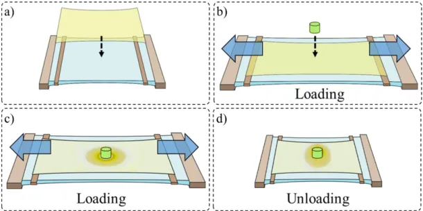
Figure 11 illustrates the setup and procedure for deforming (stretching/releasing) hydrogels with 2D Liesegang patterns in PAA hydrogel. Prepared PAA hydrogel (section 2.2) was removed from the mold and was transferred on Ecoflex substrate (as mentioned in section 2.7). To apply load on the hydrogel sample (stretching), we used an Ecoflex substrate, on which the gel was placed. Direct attachment of hydrogel to the holders without the Ecoflex substrate would break the hydrogel at the clamp jaws due to a high load of perpendicular forces. Then, the stamp (2.6) was placed gently on the hydrogel center as described in the individual experiments.
1D stretching setup was prepared similar to the 2D setup; using (1.5 cm × 7 cm × 2
mm) hydrogels and the cuboid stamp was placed on the hydrogel center. All samples were kept in a container, in which water was sprayed to cease evaporation of water from the hydrogel and the stamp during the experiments.
Figure 11. Schematic illustration of 2D uniaxial stretching setup. (a) Transferring hydrogel on Ecoflex substrate. (b) Loading (stretching) sample, followed by stamp placing at the center of the hydrogel. (c) Formation of the patterns on the hydrogel upon loading. (d) The sample unloading.
20
2.9. Chemical erasing of the LPs formed in the hydrogels
Precipitation patterns formed on PAA hydrogels were removed using three different solutions. Hydrogels with patterns were dipped in 20 ml of 0.1 M HCl, acetic acid, and NH3 solutions and were left in the solutions for 2 hours.
2.10. Polymerization of pyrrole on LP patterns
1 ml of 0.1 M HCl was added to 28.8 ml of deionized water. Then, 0.2 ml of Pyrrole solution was added to this solution. The mixture was sonicated and shaken vigorously to dissolve pyrrole emulsions in water completely. The hydrogels were directly dipped in this solution/emulsion and kept in them until the development of the polypyrrole on the LP patterns [54].
2.11. Optical imaging
Images were captured using a Canon EOS Rebel T2i with a Canon EF 50 mm f/2.5 Macro Lens. Samples were illuminated using bottom-illuminated LED light box.
2.12. Image processing and analysis
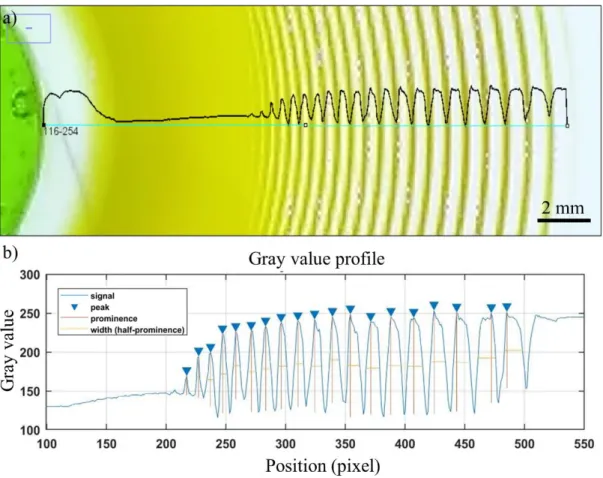
Data was extracted using ImageJ software. Figure 12a shows an example of LPs characterization using Gray-value (brightness of a pixel, in the range of 0 to 255 in ImageJ software; gray-value = 0.299red + 0.587green + 0.114blue). In Figure 12b, gray-values of an LP is shown. Data collected using ImageJ (ImageJ can produce a linear profile of the grayscale values of the image pixels.) was processed in MATLAB using a self-written MATLAB code exploiting “Findpeaks” function, to find the peaks intensity, position, width and prominence (difference between gray-value of bands and their neighbor depletion zone). Spacing coefficient of patterns signal (𝑋𝑛+1/𝑋𝑛 = 1 +
𝑝) was retrieved form of the slope of 𝑙𝑛(𝑋𝑛) vs. n, where 𝑋𝑛 is the position of each precipitation band and n is the band number and 𝐿𝑛(𝑋𝑛)/𝑛 = 𝐿𝑛(1 + 𝑝). Width of bands was retrieved by calculating full width at half maximum of negative of gray-value (-1 × gray-gray-value).
21
Figure 12. Gray-value analysis of Liesegang patterns in Figure 13a. (a) Gray-value profile of LPs in loading (stretching) direction just before unloading. (b) Peaks analysis of gray-value profile including peaks intensities, widths (full width at half maximum) and peak prominences (difference between gray-value of bands and their neighbor depletion zone).
22
CHAPTER 3
3. RESULTS AND DISCUSSION
3.1. Formation of post-patterns in 1D, 2D, and 3D PAA hydrogels 3.1.1 Formation of post-patterns in 2D PAA hydrogels
The changes in the LP patterns affected by elastic mechanical deformation of the gels shown so far are 1) the alteration of the aspect ratio of the whole pattern by the deformation, 2) the formation of the post-patterns (PP) upon the continuing reaction/diffusion after the unloading. In this section, we would like to concentrate more on the latter phenomenon, the formation of the post-patterns, since they are more information-rich. Post-patterns (PP) stand out as irregularities in the reaction-diffusion system as a result of previously experienced mechanical input. They can be detected visually, which make them suitable for further analysis without utilization of any special technique. In Figure 13, the formation of PPs in a stretched polyacrylamide gel, where CuCrO4 precipitation patterns form, is shown. Firstly, the stretchable
polyacrylamide gel was deformed uniaxially and elastically (Figure 13a) for 24 hrs. During this time Cu2+ ions from the agarose stamp diffused into the hydrogel and the LP patterns formed as expected, as concentric circular rings (aspect ratio =1.0) around the stamp, following the LP spacing and width laws. (As mentioned above, spacing law (spacing coefficient: 1 + 𝑝 = 𝑋𝑛+1/𝑋𝑛) is one of the governing laws in LPs, which means that spacings between the consecutive pattern bands form a mathematical geometric series.) After releasing the load, the LP pattern adopted an aspect ratio higher than 1.0 (as also shown in Figure 6). Note that in the unloaded gel, even though the formed LPs were distorted because of the unloading, to concentric ovals, they still follow the ‘LP laws’. If the reaction/diffusion is let to continue after
23
this point, the PPs start to develop, which have distinct characteristics: 1) the intra-ring depletion zone (the space between the consecutive intra-rings, where there is no significant precipitation detected in regular LPs) has a darker color, 2) in this region, PPs deviate from the LP-spacing-law; a few consecutive bands form as equidistant rings. Figure 13 also shows a ‘recovery’ of the reaction-diffusion system - after formation of a couple of PPs, the system reverts back to forming regular LPs.
c) The patterns -hydrogel. (a 2D ration of PP formation in demonst A typical . 13 Figure ) PAA polyacrylamide ( containing -2 4 into CrO 2+ f Cu o formed by diffusion 4 of CuCrO
gel during and after elastic deformation of the gel. (a) Formation of patterns in a stretched (40% strain) PAA hydrogel after 24 hours. (b) The change in the aspect ratio of patterns after unloading (releasing) the stress. (c) Post-patterns formed in the sample after unloading (release) (photo taken 18 hours after unloading). Inner electrolyte
(potassium chromate) = 0.01 M, outer electrolyte (copper chloride) = 1 M, acrylamide = 13.5 w%, BIS = 0.056 w%, KPS = 0.187 w%, TEMED = 0.0001 w%. T = 20 °C. For details of the gel preparation and loading setup please see Chapter 2.
![Figure 1. Examples of Liesegang patterns. (a) Periodic pattern formation in a volcanic rock [9], reprinted with permission from [10]](https://thumb-eu.123doks.com/thumbv2/9libnet/5874194.121078/21.892.181.779.797.998/examples-liesegang-patterns-periodic-formation-volcanic-reprinted-permission.webp)