©BEYKENT UNIVERSITY
CASCADABLE CURRENT MODE MULTIFUNCTION BIQUADRATIC FILTER
Mahmut ÜN1, Fırat KAÇAR2
1Beykent University, Department of Electronics and
Communication Engingeering, Ayazaga, Sisli, İstanbul, TURKEY, umahmut@beykent. edu.tr,
2 ' • •
İstanbul University, Department of Electrical-Electronics Engineering, Avcilar, Istanblu, TURKEY, [email protected] ABSRACT
A novel three inputs and single output current-mode universal biquadratic filter with high-input and high-output impedance using three plus-type differential difference current conveyors, grounded capacitors and resistors is presented. The proposed circuit offers the following features: realization of all the standard filter functions that is high pass, bandpass, lowpass, notch and all pass filters, no requirements for component matching conditions, the use of only grounded capacitors and resistors, high input and high output impedance and low active and passive sensitivities.
Keywords: Active filters, biquadratic filter, current mode circuits, current conveyors,
differential difference current conveyor (DDCC) ÖZET
Üç artı-tip diferansiyel fark akım taşıyıcı, topraklı kapasiteler ve dirençleri kullanarak, yüksek giriş ve çıkış empedansları olan üç girişli ve bir çıkışlı akım modlu yeni bir ikinci derece üniversal filtre tanıtılmıştır. Önerilen devrenin aşağıdaki özellikleri bulunmaktadır: Yüksek, alçak, band geçiren, band durduran ve tüm geçiren standart filtre fonksiyonlarının hepsi bu devreyle gerçeklenebilir. Gerçeklemede elemanlar için denkleştirme koşulları gerekmez ve yalnız topraklı kapasite ve dirençler kullanılır. Devrenin yüksek giriş ve çıkış empedansları, küçük aktif ve pasif duyarlıkları vardır.
Anahtar kelimeler: Aktif filtreler, ikinci dereceden filtreler, Akım modu devreler, Akım
1. INTRODUCTION
Multifunction type active filters are especially versatile, since the same topology can be used for different filter functions. In spite of the fact that numerous current mode multifunction filters are reported in literature, most of them use at least three active elements, and only few can realize all types of current transfer functions using reduced number of active elements.
The applications and advantages in the realization of various active filter transfer functions using current conveyors have received considerable attention [1]. Second order active filters with high input impedance are great of interest because several cells of this kind can be directly connected in cascade to implement higher order filters [2].
Recently, many voltage-mode universal biquadratic filters with three inputs and one output were proposed [3-11]. All circuits employ different types second generation current conveyors (CCIIs) and they are voltage mode circuits. However, none of their responses have the advantage of high input impedance and all pass requires component matching condition. Chang and Tu [9] employed two plus-type CCIIs, two capacitors and three resistors with four inputs and single output to realize a universal biquad. Horng [10-11] proposed two new high input impedance-voltage mode universal biquadratic filters with three inputs and single output using three plus-type CCIIs. However, these circuits employ floating capacitors and need a voltage inverter to realize all pass filter response. Moreover, the active and passive sensitivities are not small.
In this paper, a new high-input and high output impedance current-mode universal biquadratic filter with three inputs and single output using three plus-type differential difference current conveyors (DDCCs) [12] is presented. The new circuit uses two grounded capacitors and five grounded resistors which are suitable for integrated circuit implementation [13]. The circuit needs neiher any inverting type voltage input signal nor any
critical component matching conditions.Moreover, the circuit has low active and passive sensitivities.
2. PROPOSED CIRCUIT
The differential difference current conveyor (DDCC) was proposed in 1996 [12], and it enjoy the advantages of CCII and DDA such as larger signal bandwidth, greater linearity, wider dynamic range, simple circuitry, low power consumption, high input impedance and arithmetic operation capability.Moreover, it has three high input voltage terminals (Y terminals) that make easy to synthesize circuits.
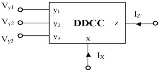
V y 1 y i V y 1 y i V y 2 y2 V y 2 y2 y3 V y 3 y3
Figure 1. The Symbol of the DDCC
Using standard notation, the port relations of an ideal DDCC shown in Fig.1 can be characterized by
V, yi ' y 2 y 3 1 - 1 1 0 " _ Vy i 0 0 0 0 Vy 2 0 0 0 0 Vy 3 0 0 0 ± 1 I , (1) x z
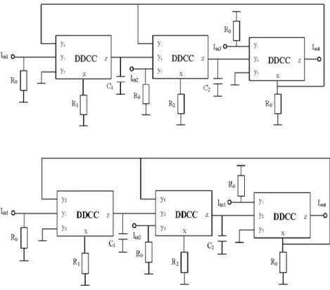
where the plus and minus signs indicate whether the conveyor is configured as a noninverting or inverting circuit, termed DDCC+ or DDCC-. The proposed configuration is shown in Fig.2 The transfer functions can be expressed as
j = S2QC2I,n3 ~ S ( ( ( (2I, n 2 +G!G2 IM
out s 2ClC2 + sCfi2 + ( (
From (2), we can see the following:
1) If Iini=Ijn2=0 , a second order high pass filter can be obtained
with Iout/ Iin3
2) If Iin1=Iin3=0 , a second order bandpass filter can be obtained
with Iout/ Iin2
3) If Iin1=Iin3=0 , a second order bandpass filter can be obtained
with Iout/ Iin2
4) If Iin2=Iin3=0 , a second order low pass filter can be obtained
with Iout/ Iini
5) If Iin2=0 and Iin1=Iin3=Iin , a second order notch filter can be
obtained with I,ut/ Ijn
6) If Iin 1=Iin2=Iin3=Iin , a second order all pass filter can be
obtained with Iout/ Iin
Thus, the circuit is capable of realing all filter functions. The circuit requires the minimum number of passive components with no requirement for matching conditions. Moreover, the three input signals, Iin1, Iin2 and Iin3 are connected to the high input
impedance input nodes of the three plus-type DDCCs (the y port of the plus-type DDCC), respectively. The output signal, Iout is
connected to the low output impedance output node of the plus-type DDCC (the z port of the plus-plus-type DDCC).
Figure 2. DDCC-based current mode universal biquad
So the circuit enjoys the advantage of having high input and low output impedance. Note that the low output impedance makes the proposed circuit easy to be connected to next stage without any buffer. Furthermore, the new circuit uses only grounded capacitors and resistors, which are suitable for integrated circuit implementation. The employs of only plus type DDCCs simplify the circuit configuration.
3. SENSITIVE ANALYSIS
Taking the nonidealities of the DDCC into account, the relationship of the terminal voltages and currents can be rewritten as
yi -y 2 y3 a ki 0 0 -a 0 0 k 2 a k 3 0 0 0 0 0 ±Pk V yi V y2 V y3 (3)
where a =1 -^ i v and£Hv (|£Hv |<<1) denotes the voltage
tracking error from Vyi terminal to Vx terminal of the kth DDCC,
ak 2 = 1 - ei 2 v and ek2v (|ei2v ( « 1 ) denotes the voltage tracking
error from Vy2 terminal to Vx terminal of the kth DDCC,
andei3v (|eMv |<<1) denotes the voltage tracking
ak 3 = 1 Sk 3v
error from Vy3 terminal to Vx terminal of the kth DDCC and
Pk = 1 -efe- a n d e ( | e | < < 1 ) denotes the current tracking error
of the kth DDCC. The denominator of nonideal voltage transfer function in Fig.2 becomes
D{s) = s 2CiC2 + sCiG2a2ia32P2 + GiG2ai2a22a32Pi p (4)
The resonance angular frequency wo and quality factor Q are
obtained by Wo = C C C1C2 (5) 0 = ^ a2 i \ C2Giai 2a2 2 ^ 1 C iG 2a 32P2 (6)
The active and passive sensitivities of wo and Q are calculated as
x
0
0 0
x z
C<wo _ C™» _ C™» _ 1
s ^ ^ ^ ^ - A ^ - A Q.C - 2 ,
S*a,, - 1 .
All the active and passive absolute sensitivities are equal are less than one.
4. SIMULATION RESULTS
The proposed circuit was simulated using PSPICE. The DDCC was realized by the CMOS implementation using TSMC 0.35-p.m CMOS technology process parameters [14]. Aspect ratios of the MOS transistors were chosen in Table I [12] and the power supply was ±1.65 V. The biasing voltage Vb was taken as -0.76
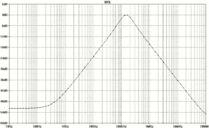
V. Fig.3a,b,c,d, and e, respectively, represents the simulated amplitude frequency responses and phase frequency responses for LP, HP, BP, notch and all pass filters which designed with fo=159
kHz, C1 =C2 =1 nF, R0=10 kQ and R1=R2 =1 kQ . Furthermore,
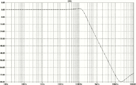
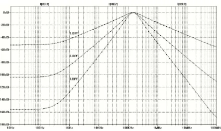
to demonstrate the performance of higher order filter which is made up more than one cascaded biquad filter sections, cascaded two and three BP filter sections having the same component values given above are simulated with PSPICE and simulation results are shown in Fig.4. All simulation results are in good agreement with the predicted theory. Actually, the parasitic resistances and capacitances , and nonidealities of the DDCCs cause the small deviations from the theoretical values in the frequency responses of the simulated filters.
5. CONCLUSION
In this study, a new three inputs and single output current mode universal biquadratic filter with high input and high output impedance is presented.The proposed circuit uses three plus type
Figure 3a. PSPICE simulation results for the LP filter
Figu re 3b. PSPICE simulation results for the HP filter
Figure 3c. PSPICE simulation results for the BP filter
Figure 3e. PSPICE simulation results for the AP filter
DDCCs, two grounded capacitors and five grounded resistors and also offers following advantages: high input and high output impedance which is cascadeable without any buffer, low active and passive sensitivities , the use of only three plus type DDCCs that simplifies the circuit configuration, the use of only grounded capacitors and resistors which are suitable for integrated circuit implementation, the versatility to synthesize low pass, bandpass, high pass, notch and all pass responses without component matching conditions.
REFERENCES
[1] Wilson B, Recent developments in current conveyor and current mode circuits, Proc. IEEE Circuits, Devices, Syst, vol. 137, no.2, pp 63-77, Apr. 1990.
[2] Fabre A, Dayoub F, Duruisseau L, Kamoun M, High input impedance insensetive second order filters implemented from current conveyors, IEEE Trans Circuits, Syst I, Fundam Theory Appl , vol.41, no.12, pp 918-921, Dec 1994.
[3] Ozoguz S, Gunes E O, Universal filter with three inputs using CCII+s, Electron Lett, vol.32, no.23, pp 134-135, Nov 1996. [4] Chang C M, Lee M S, Comment: Universal voltage mode filter with three inputs and one output using three current conveyors and one voltage follower, Electron Lett, vol.31, no.5, pp 353, Mar 1995.
[5] Horng J W, Tsai C C, Lee M H, Novel universal voltage mode biquad filter with three inputs and one output using only two current conveyors, Int J Electron, vol.80, no.4, pp 543-546, Apr 1996.
[6] Horng J W, Lee M H, Cheng H C, Chang C W, New CCII-based voltage mode universal biquadratic filter, Int J Electron, vol.82, no.2, pp 151-155, Feb 1997.
[7] Liu S I, Lee J L, Voltage mode universal filters using two current conveyors, Int J Electron, vol.82, no.2, pp 145-147, Feb
1997.
[8] Chang C M, Multifunction biquadratic filters using current conveyors, IEEE Trans Circuits Syst II: Analog Digit Signal Process, vol.44, no.11, pp 956-958, Nov 1997.
[9] Chang C M, Tu S H, Universal voltage mode filter with four inputs and one output using two CCII+s, Int J Electron, vol.86, no.3, pp 305-309, Mar 1999.
[10] Horng J W, High input impedance voltage mode universal biquadratic filter using three plus Type CCIIs, IEEE Trans Circuits Syst II: Analog Digit Process, vol.48, pp 996-997, Oct 2001.
[11] Minaei S. And Turkoz S., Current-mode electronically tunable universal filter using only plus-type current controlled conveyors and grounded capacitors, ETRI journal, Vol.26, No.4, 2004
[12] Chiu W, Liu S I, Tsao H W, Chen J J, CMOS differential difference current conveyors and their applications, Proc IEE Circuits Devices Syst, vol.143, no.2, pp 91-96, Apr 1996.
[13] Bhusan M, Newcomb R W, Grounding of capacitors in integrated circuits, Electron Lett , vol.3, pp 148-149, 1967. [14] Elwan H O, Soliman A M, Novel CMOS differential voltage current conveyor and its applications, Proc IEE Circuits Devices Syst, vol.144, no.3, pp195-200, Jun 1997.