© TÜBİTAK
doi:10.3906/fiz-1908-6 h t t p : / / j o u r n a l s . t u b i t a k . g o v . t r / p h y s i c s /
Research Article
Atomic layer deposition of zirconium oxide thin film on an optical fiber for
cladding light strippers
Ali KARATUTLU∗
Bilkent University-UNAM Institute of Material Science and Nanotechnology and National Nanotechnology Research Center, Bilkent University, Ankara, Turkey
Received: 16.08.2019 • Accepted/Published Online: 07.01.2020 • Final Version: 12.02.2020
Abstract: Cladding light strippers are essential components in high-power fiber lasers used for removal of unwanted
cladding light that can distort the beam quality or even damage the whole fiber laser system. In this study, an Atomic Layer Deposition system was used for the first time to prepare the cladding light stripper devices using a 40 nm thick zirconia layer grown on optical fiber. The thickness of the zirconia coating was confirmed using the Scanning Electron Microscopy (SEM) and the Ellipsometry techniques. The elemental analysis was also performed using the wavelength dispersive X-ray spectroscopy technique. The Raman spectroscopy and XRD data confirm the structure of the atomic layer deposition-grown zirconia thin films to be predominantly amorphous. The cladding light stripper devices formed using the zirconia thin films with the lengths of 8.5 and 15.5 cm were able to strip approximately 30% (~1.5 dB) and 40% (~2.3 dB) of the unwanted cladding light.
Key words: Fiber laser, atomic layer deposition, thin film, zirconium oxide, cladding light stripper
1. Introduction
Cladding light strippers (CLSs) are optical devices utilized to remove the unabsorbed light propagating in the cladding layer of an active fiber. Eliminating the unwanted cladding light is crucial particularly for the high-beam quality and safe operation of high-power fiber lasers and amplifiers [1]. Some portion of the cladding light can also be due to amplified spontaneous emission (ASE) of the active core fiber, the light leakage due to imperfect splices and the bend losses causing backward signal radiation [2]. The cladding light is removed from the cladding layer of an optical fiber via relatively higher-index material coatings or the surface deformations/textures created on the cladding. For the higher-index material coatings, mostly polymers in a cascaded arrangement are utilized owing to the ease of the process despite the fact that the polymers have low thermal conductivity and tend to degrade for the long-term operation at high-power applications [3,4]. Soft metals are also shown for the preparation of the CLSs which are robust and have advantages over conventional (degrading) polymers when used in high power applications; nevertheless, the CLS devices coated with certain metals such as Au and Sn suffered localized heating [5]. Furthermore, the higher-index capillary coating is another promising method of the CLSs fabricated by collapsing the borosilicate capillary on the fiber via hydrogen-oxygen torch [6]. Similarly, the CO2 laser beam deposition technique was demonstrated for the formation of the functional coating layers
onto the fiber surface for removing the unwanted cladding light [7]. On the other hand, the CO2 laser beam was
also utilized for the surface textured CLS preparation [2]. For the chemical etching of an optical fiber, the acidic
∗Correspondence: [email protected]
fluorides or HF paste is one of the widely utilized routes. Such etching processes create surface deformations in the glass network that further acts light scattering points in the case of interacting the cladding light [8,9]. However, removal of the light with low NA light is not managed well and the fiber can become respectively more fragile after the etching procedure. This can make handling of the device more challenging mostly at the time of cleaving and splicing.
In this study, the atomic layer deposition (ALD) technique was demonstrated as a novel method for the fabrication of CLSs. It was shown that even a very thin film grown in nanoscale can partially remove the unwanted light propagating in the cladding of an optical fiber. To the best of author’s knowledge, this is the first study on the formation of the CLS fabricated by an ALD system.
2. Materials and methods
2.1. The CLS device fabrication using the ALD system
The CLS devices were fabricated by a precursor called Tetrakis(dimethylamino)zirconium packaged for use in deposition systems and utilized as purchased from Sigma-Aldrich. An optical fiber (LMA-GDF 20/400-M, Core NA = 0.0065± 0.0005, the First Cladding NA(5%) = 0.46) was purchased from Nufern and used upon stripping its polymer coatings. The precursor reactor was heated at 90 °C for its sublimation and the reaction chamber was preserved at 150 °C. After stabilization of the temperatures, the precursor was carried by N2 gas
and oxidized with H2O to obtain the zirconia thin films. The fabrication process was completed with one cycle
of sublimation and deposition process approximately at the end of 2 h. In addition to optical fibers, 10× 10
mm silicon (Si, 100) wafers (thickness of 500 µm, p-type high resistivity (1–10 Ohm-cm) and 10× 10 mm
glass slides (thickness of 160 µm) were inserted simultaneously for the further characterization of the grown thin films.
2.2. Characterizations and the performance tests
For the characterizations of the grown zirconium oxide thin films, a scanning electron microscope (SEM, Model: FEI NanoSEM) equipped with a wavelength dispersive X-ray Spectroscopy (WDS, Model: Oxford Instruments INCAWave) at 20 kV, the ellipsometry technique (Model: J. A. Woollam Co., Inc. Spectroscopic Ellipsometers, V-VASE), UV-VIS Absorption Spectroscopy (Model: Carry5000), and photoluminescence spectroscopy (Model: Flurolog, Horiba JOBIN YVON) were operated to determine the morphological, elemental, and optical proper-ties of the films. Furthermore, A Raman spectroscopy (Model: Witec SNOM Raman 300 Aplha coupled with a diode laser at λ= 532 nm) technique was utilized for the structure of the ALD-grown thin films using two different gratings with the groove densities of 1200 g/mm and 600 g/mm. Further structural investigation was performed by collecting the XRD measurement using an XRD diffractometer (Model: PANalytical X’Pert PRO) from 20°to 80°and Cu as anode material. The SEM studies were performed both in secondary electron imaging (SEI) and backscattered electron imaging (BEI) modes. The ellipsometry measurements were performed for the thin films coated on the glass slide and the Si wafer. The glass slide and the Si wafer samples were placed next to the optical fiber within the ALD chamber.
The CLS device performance tests were performed by a simple set up consisting of two diodes (Model: Dilas at λ= 976 nm , N A = 0.22 , max. power = 330 W ) integrated by a pump combiner, a DC power supply, an Al plate for the CLS device enclosure, and a power meter (Model: Ophir 30A-P-17, operating range:
60mW-30 W) all located on an optical table. The stripping behavior of the devices was recorded using a near-infrared (NIR) imaging camera.
Table 1. Elemental Analysis of the CLS device. Element Weight% Weight% Atomic%
Zr Lα 74.031 0.712 33.333
O Kα 25.969 - 66.667
3. Results and discussion
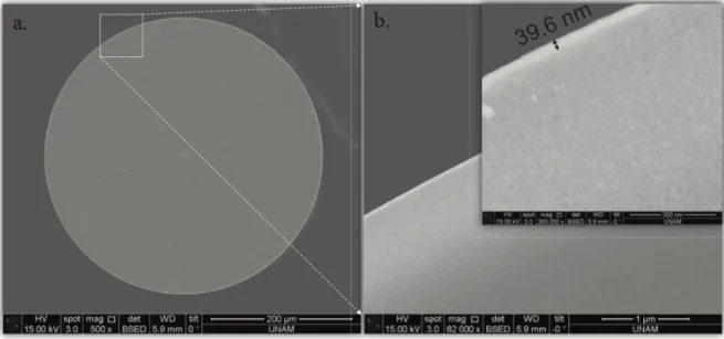
Figure 1 shows the thickness and morphological features using the SEM in the BEI modes. The results in Figures 1a and 1b show that the fused silica fiber and the thickness of the thin film coated on its cladding were measured to be 400 µm and 39.6 nm in size respectively. The WDS measurement as shown in Table confirms the zirconium oxide thin films at the edge of the fiber (inset of Figure 1b). The size of the zirconia thin film was also crosschecked with the Ellipsometry measurements as an indirect probe generally conducted for the determination of the thickness of materials from their optical properties [10,11]. Figure 2 gives the experimental data and the fits using the Cauchy model. The size of the thin films on the glass slide and the Si wafer were 41.5 nm (± 0.7 nm) and 33 nm (± 0.7 nm) and the mean squared errors (MSE) were 7 and 1.5,
respectively. Despite the fit for the thin film coated on the glass slide is not as well as that coated on the Si wafer, the thickness determined by the ellipsometry technique can be considered consistent with that found in the SEM technique. On the other hand, this result also implies the anisotropy of the ALD-grown thin film on the glass substrate since the growth dynamics of zirconia thin films can alter due to the difference in the initial roughness of the various substrates including Si and glass [12].
Figure 1. The cross-sectional SEM images recorded in the BEI modes.
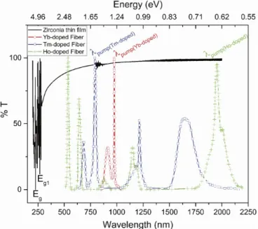
Furthermore, Figure 3 shows the UV-VIS-NIR transmission results demonstrating the zirconium oxide thin film coating mainly absorbing at the band gap edges (distance between the highest occupied molecular orbital (HOMO) to the lowest unoccupied molecular orbital (LUMO)) Eg and Eg1 of the zirconium oxide
and transmitting the photons at relatively longer wavelengths. This result can be considered to be consistent with the previous studies of the zirconia samples yielding negligible absorption in the visible and NIR regions [13,14] and that the band gap are around 5.1 eV [15]. The zirconium oxide thin film has approximately 95.5% and 96.2% transparencies at 915 nm and 976 nm respectively (the pump wavelengths of the Yb-doped fiber lasers [16,17]). The % transmission rises further for the relatively longer wavelengths when approaching 2 µm including the pump wavelengths of Tm- and Ho-doped fiber lasers [18,19]. Therefore, the ALD-grown zirconia thin is mostly transparent in a wide range from visible to infrared regions which will lead to very low absorption and thermal load on the optical fiber when used in cladding light stripping applications.
p
a.
b.
Figure 2. Optical reflectance measurements of the zirconia thin films on a. the glass slide and b. the Si wafer at three
different angles of 65°, 70°, 75°using the Ellipsometry technique. λp stands for the pump wavelength utilized for the
Yb-doped fiber lasers.
Figure 3. The background substracted % transmission measurement of the zirconia film coated on the glass slide
recorded from 200 nm to 2000 nm. The normalized absorption cross-sections of Tm-doped fiber, Yb-doped fiber, and Ho-doped fiber are given for comparison.
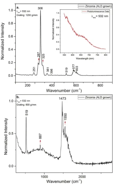
To understand the structure of the ALD-grown zirconia thin films, Raman spectroscopy, and the XRD studies were performed. The Raman data is shown in Figure 4a for the ALD-grown zirconia in order to determine
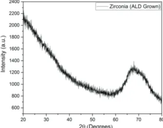
its structure. The bands are located at 251 cm−1, 306 cm−1, 358 cm−1, 520 cm−1, 577 cm−1, and 603 cm−1. Considering the three structures, the Raman data could initially be considered to be more consistent with the Raman data of the cubic phases (RRUFF ID: X080012 and RRUFF ID: R110112 from Gemological Institute of America). As also suggested in the latter study that the Raman spectrum obtained by the excitation wavelength of 532 nm is overwhelmed by the fluorescence spectrum. The inset in Figure 4 confirms that the zirconia thin film has a PL emission by the excitation wavelength of 532 nm. The studies demonstrated that the structure of as-deposited zirconia thin films could be predominantly amorphous in addition to partial crystalline phases at the deposition temperature of 150 °C [10]. Therefore, additional investigations were conducted for further investigation of the structure of the ALD grown zirconia thin films. In Figure 4b, Raman data with a relatively smaller grove density (600 g/mm) with respect to that shown in Figure 4a (1200 g/mm) was collected so as to reduce the PL intensity. The result in Figure 4b gives rather much broader peaks suggesting the structure is predominantly amorphous. The XRD data given in Figure 5 confirms the structure of the ALD grown zirconia thin film is amorphous.
Figure 4. The Raman data of the zirconium oxide thin film (grown on the thin glass slide) using the gratings with the
grove densities of a. 1200 g/mm and b. 600 g/mm. The inset shows the PL data obtained at the excitation wavelength of 532 nm.
The refractive indices for the zirconia thin films grown on the glass slide and the Si wafer were determined from the fit of the Cauchy model to the dispersion curve and found to be 2.12 (±0.02 nm) and 2.11 (±0.02 nm)
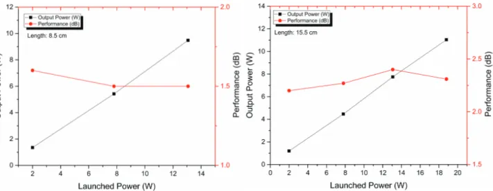
respectively. Besides, zirconia is a well-known refractory (thermal barrier coating) material utilized at high-temperature applications [20]. The relatively high refractive index and high transmission emphasize the zirconia thin film as a potential for high-power cladding light stripping applications due to the fact that the coating will mostly lead to the removal of the unwanted cladding light. For this quest, the zirconia grown on the optical fiber with a length of 8.5 cm was integrated to the two high-power pump diodes by a pump combiner (Figure 6a). The NIR image taken at the launched power of 5 W of in Figure 6b demonstrates that the stripping behavior is quite homogenous along with the CLS device. The CLS device as given in Figure 7a is capable of removal of approximately 30% of the cladding light (~1.5 dB) when the CLS device had a length of 8.5 cm. Figure 7b also demonstrates that increasing the length of CLS device to 15.5 cm produces a stripping efficiency of 40% of the cladding light (~2.3 dB). Other coating methods used to form CLSs including the soft-metals coating [5] or the high-index polymer coating [3] utilize a larger contact area either increasing the thickness of the coating or the length of CLSs thus able to strip more unwanted cladding light. Therefore, the performance of the ALD-grown Zirconia-based CLS device can be further enhanced particularly for the high-power applications despite the fact that the CLS device is almost stable and the efficiency changes are less than ±5% when increasing the launched
power.
Figure 5. The XRD data of the zirconia thin film grown on the silicon wafer.
a.
The CLS Device
Powermeter
The CLS Device
Direction of the Light
b.
Figure 6. a. An optical image of the CLS Device with a length of 8.5 cm under white light and b. its NIR image taken
Figure 7. The performance and stability tests of the CLS devices at the lengths of a. 8.5 cm and b. 15.5 cm.
4. Conclusion
In summary, the CLS devices based on the nanozirconia thin film fabricated by an ALD system were demon-strated for the first time. The CLS devices with a length of 8.5 cm and 15.5 cm were approximately able to strip 1.5 dB and 2.3 dB of the pumped light respectively owing to a relatively larger refractive index and low absorption of the zirconia thin films. The ALD system can also be utilized to increase the thickness of thin films so that an improved CLS performance can be obtained. Furthermore, the ALD technique allows to use different precursors to grow hetero-structured thin films layer by layer with a small degree of difference in refractive index compared to the optical fiber.
Acknowledgments
The author thanks for the technical support provided by the clean room staff of UNAM, Dr. Gökçe Çelik and Enver Kahveci for the support in the ellipsometry analysis and the XRD measurements respectively, Mr. Seyitali Yaşar for his glassworks and Mr. Yakup Midilli for the help during the CLS device performance tests. The author is also thankful to Ms. Elif Yapar Yıldırım and Dr. Bülend Ortaç for the fruitful discussion.
References
[1] Tünnermann A, Schreiber T, Röser F, Liem A, Höfer S et al. The renaissance and bright future of fibre lasers. Journal of Physics B: Atomic, Molecular and Optical Physics 2005; 38: S681–93. https://doi.org/10.1088/0953-4075/38/9/016
[2] Boyd K, Simakov N, Hemming A, Daniel J, Swain R et al. CO_2 laser-fabricated cladding light strippers for high-power fiber lasers and amplifiers. Applied Optics 2016; 55: 2915. https://doi.org/10.1364/AO.55.002915 [3] Yan P, Sun J, Huang Y, Li D, Wang X et al. Kilowatt-level cladding light stripper for high-power fiber laser. Applied
Optics 2017; 56: 1935. https://doi.org/10.1364/AO.56.001935
[4] Guo W, Chen Z, Zhou H, Li J, Hou J. Cascaded cladding light extracting strippers for high power fiber lasers and amplifiers. IEEE Photonics Journal 2014; 6: 1–6. https://doi.org/10.1109/JPHOT.2014.2320736
[5] Babazadeh A, Nasirabad RR, Norouzey A, Hejaz K, Poozesh R et al. Robust cladding light stripper for high-power fiber lasers using soft metals. Applied Optics 2014; 53: 2611. https://doi.org/10.1364/AO.53.002611
[6] Bansal L, Supradeepa VR, Kremp T, Sullivan S, Headley C. High power cladding mode stripper. In: Shaw LB, editor. Proc. of SPIE: Fiber Lasers XII: Technology, Systems, and Applications, vol. 9344, 2015, p. 93440F. https://doi.org/10.1117/12.2079181
[7] Boehme S, Hirte K, Fabian S, Hupel C, Schreiber T et al. CO2 -laser-based coating process for high power fiber application. SPIE Photonics West 2014-LASE: Lasers and Sources 2014; 8968: 89680Z. https://doi.org/10.1117/12.2036357
[8] Kliner A, Hou K-C, Plötner M, Hupel C, Stelzner T et al. Fabrication and evaluation of a 500 W cladding-light stripper. Advanced Solid-State Lasers Congress 2013; 8616: AM2A.3. https://doi.org/10.1364/ASSL.2013.AM2A.3 [9] Yin L, Yan M, Han Z, Wang H, Shen H et al. High power cladding light stripper using segmented corrosion method:
theoretical and experimental studies. Optics Express 2017; 25: 8760. https://doi.org/10.1364/OE.25.008760 [10] Wan Y, Bullock J, Hettick M, Xu Z, Yan D et al. Zirconium oxide surface passivation of crystalline silicon. Applied
Physics Letters 2018; 112: 201604. https://doi.org/10.1063/1.5032226
[11] Gupta R, Vaid R. Effect of Post Deposition Annealing on ALD-ZrO2/SiON Gate Stacks for Advanced CMOS Technology. ECS Transactions 2016; 75: 67–73. https://doi.org/10.1149/07517.0067ecst.
[12] Gambardella A, Berni M, Russo A, Bianchi M. A comparative study of the growth dynamics of zirconia thin films deposited by ionized jet deposition onto different substrates. Surface and Coatings Technology 2018; 337: 306–12. https://doi.org/10.1016/j.surfcoat.2018.01.026
[13] Ciuparu D, Ensuque A, Shafeev G, Bozon-Verduraz F. Synthesis and apparent bandgap of nanophase zirconia. Journal of Materials Science Letters 2000; 19: 931–3. https://doi.org/10.1023/A
[14] Ramola RC, Rawat M, Joshi K, Das A, Gautam SK et al. Study of phase transformation induced by electronic excita-tion in pure and yttrium doped ZrO 2 thin films. Materials Research Express 2017; 4. https://doi.org/10.1088/2053-1591/aa8671
[15] Sayan S, Nguyen NV, Ehrstein J, Emge T, Garfunkel E et al. Structural, electronic, and dielectric properties of ultrathin zirconia films on silicon. Applied Physics Letters 2005; 86: 152902. https://doi.org/10.1063/1.1864235 [16] Paschotta R, Nilsson J, Tropper AC, Hanna DC. Ytterbium-Doped fiber ampli?ers. IEEE Journal of Quantum
Electronics 1997; 33: 1049–56. https://doi.org/10.1109/3.594865
[17] Jauregui C, Limpert J, Tünnermann A. High-power fibre lasers. Nature Photonics 2013; 7: 861–7. https://doi.org/10.1038/nphoton.2013.273
[18] Creeden D, Johnson BR, Rines GA, Setzler SD. High power resonant pumping of Tm-doped fiber amplifiers in core-and cladding-pumped configurations. Optics Express 2014; 22. https://doi.org/10.1364/OE.22.029067
[19] Simakov N, Li Z, Jung Y, Daniel JMO, Barua P et al. High gain holmium-doped fibre amplifiers. Optics Express 2016; 24: 13946. https://doi.org/10.1364/oe.24.013946
[20] Clarke DR, Phillpot SR. Thermal barrier coating materials. Materials Today 2005; 8: 22–9. https://doi.org/10.1016/S1369-7021(05)70934-2