approaches a constant maximum value for tapers longer than 15 mm.
CONCLUSION
Planar transmission-line impedance transformers with an uncon-ventional multilayered structure obtained by deposition of high-dielectric-constant thin films on bulk substrates have been de-signed and their performance have been compared to those of transformers printed on very high-dielectric-constant (r ⫽ 80) bulk substrates. The propagation characteristics of the tapered lines were investigated using the finite-element method through a com-mercially available software package. The dispersion effects and impedance variation with respect to frequency were taken into account in the analysis. The response of the proposed structure does not deteriorate significantly with frequency, thus allowing operation in an acceptable range up to 40 GHz. The investigation of the propagation characteristics of short electrical pulses on the unconventional multilayered structure and on very high-dielectric-constant bulk-substrate tapers was carried out, confirming the better performance of the proposed structure. The propagation of very short pulses without substantial distortion was verified. Fi-nally, the effects of the multilayered taper length on the perfor-mance were assessed.
The newly proposed multilayered structure presented attractive results. The achieved effective dielectric constant is very high, whereas the structure has very low dispersion, thus allowing the construction of compact high-frequency devices. The lines have both simple cross sections and comfortable transversal dimensions for a wide range of impedances, thus leading to less expensive manufacture. The results obtained thus far indicate that this struc-ture may be suitable for many other applications in microwave components.
ACKNOWLEDGMENT
This work was supported by the Research and Development Cen-ter, Ericsson Telecomunicac¸o˜es S.A., Brazil.
REFERENCES
1. M.C.R. Carvalho, W. Margulis, and J.R. Souza, A new, small-sized transmission-line impedance transformer with applications in high-speed optoelectronics, IEEE Microwave Guided Wave Lett 2 (1992), 428 – 430.
2. M.C.R. Carvalho and L.F.M. Conrado, Ultra-short-pulse propagation in arbitrarily terminated tapered planar lines for optoelectronics appli-cations, Microwave Opt Technol Lett 22 (1999), 85– 87.
3. D.L.A. Seixas, L.F.M. Conrado, and M.C.R. Carvalho, Theoretical investigations on the propagation characteristics of transmission lines on substrates with very high dielectric constant, Microwave Opt Tech-nol Lett 32 (2002), 275–278.
4. B. Noren, Thin-film barium strontium titanate (BST) for a new class of tunable RF components, Microwave J 47 (2004), 210 –220. 5. A. Tombak, J.P. Maria, F.T. Ayguavives, Z. Jin, G.T. Stauf, A.I.
Kingon, and A. Mortazawi, Voltage-controlled RF filters employing thin-film barium-strontium-titanate tunable capacitors, IEEE Trans Microwave Theory Tech 51 (2003), 462– 467.
6. C. Weil, P. Wrang, H. Downar, J. Wenger, and R. Jakoby, Tunable coplanar waveguide phase shifters using ferroelectric thick films, Institut fur Hochfrequenztechnik-TUD (2002), 83– 88.
7. N. Fukushima, K. Abe, M. Izuha, et al. Epitaxial (Ba,Sr)TiO3
Capac-itors with extremely high dielectric constant for DRAM applications, IEEE-IEDM 97 (1997), 257–260.
8. A.T. Findikoglu, Q.X. Jia, I.H. Campbell, X.D. Wu, D. Reagor, C.B. Mombourquette, and D. McMurry, Electrically tunable coplanar trans-mission line resonators using YBa2Cu3O7-x/SrTiO3bilayers, Applied
Phys Lett 66 (1995), 3674 –3676.
9. D. Kuylenstierna, G. Subramanyam, A. Vorobiev, and S. Gevorgian, Tunable electromagnetic bandgap performance of CPW periodically loaded by ferroelectric varactors, Microwave Opt Technol Lett 39 (2003), 81– 86.
10. S.S. Gevorgian and E.L. Kollberg, Do we really need ferroelectrics in paraelectric phase only in electrically controlled microwave devices?, IEEE Trans Microwave Theory Tech 49 (2001), 2117–2124. 11. M. Tanabe, M. Nishitsuji, Y. Anda, and Y. Ota, A low-impedance
coplanar waveguide using an SrTiO3 thin film for GaAs power
MMIC’s, IEEE Trans Microwave Theory Tech 48 (2000), 873– 874. 12. M.C.R. Carvalho, L.F.M. Conrado, L.S. Demenicis, and D.L.A. Seixas, Propagation characteristics of transmission line transformers with different impedance variation patterns on substrates with very high dielectric constant, Microwave Opt Technol Lett 37 (2003), 174 –177.
13. Agilent 85180A high frequency structure simulator, Ver. 5.6, Septem-ber 2000.
14. R.E. Collin, Foundations for microwave engineering, 2nded., McGraw
Hill, New York, 1992. © 2005 Wiley Periodicals, Inc.
EXTENSION OF FORWARD-BACKWARD
METHOD WITH DFT-BASED
ACCELERATION ALGORITHM FOR THE
EFFICIENT ANALYSIS OF LARGE
PERIODIC ARRAYS WITH ARBITRARY
BOUNDARIES
O¨ zlem Aydin Civi,1Vakur B. Ertu¨rk,2and Hsi-Tseng Chou3
1Department of Electrical and Electronics Engineering
Middle East Technical University TR-06531, Ankara, Turkey
2Department of Electrical and Electronics Engineering
Bilkent University
TR-06800, Bilkent, Ankara, Turkey
3Department of Communications Engineering
Yuan Ze University 135 Yuan-Tung Rd. Chung-Li 320, Taiwan
Received 24 April 2005
ABSTRACT: An extension of the discrete Fourier transform
(DFT)-based forward-backward algorithm is developed using the virtual-ele-ment approach to provide a fast and accurate analysis of electromag-netic radiation/scattering from electrically large, planar, periodic, finite (phased) arrays with arbitrary boundaries. Both the computational com-plexity and storage requirements of this approach are O(Ntot) (Ntotis the total number of unknowns). The numerical results for both printed and freestanding dipole arrays with circular and/or elliptical boundaries are presented to validate the efficiency and accuracy of this approach.
© 2005 Wiley Periodicals, Inc. Microwave Opt Technol Lett 47: 293–298, 2005; Published online in Wiley InterScience (www.interscience.wiley. com). DOI 10.1002/mop.21150
Key words: phased arrays; method of moments; discrete Fourier
trans-form; iterative solvers
1. INTRODUCTION
Several design tools and numerical techniques, in particular, the integral-equation-based method of moments (MoM) solutions [1], have been implemented in computer-aided design (CAD) packages to investigate the electromagnetic (EM) radiation/scattering from
large and finite, planar freestanding phased arrays and printed structures over grounded dielectric slabs accurately, since these structures have many military and commercial applications. How-ever, the majority of conventional design and analysis methods, as well as the available CAD tools, suffer greatly from memory-storage requirements and computing time when the number of elements in the array increases rapidly.
In recent years, several MoM-based methods have been pro-posed to improve the operational count and memory-storage re-quirements of the conventional MoM [2–15]. Making use of sta-tionary or nonstasta-tionary iterative schemes in the MoM solution reduces the operational count from O(Ntot3 ) (of order Ntot3 ) to
O(Ntot2 ), where Ntot is the total number of unknowns. The fast multipole method (FMM) [4] with an operational count O(Ntot1.5) and its subsequent extensions such as multilevel FMM (MLFMM) [5] (O(Ntotlog Ntot)), as well as conjugate gradient-fast Fourier transform (CG-FFT) with O(Ntotlog Ntot) [6] are some successful efforts. Besides, infinite array approximation [7], and hybrid ap-proaches to reduce the total number of unknowns such as a hybrid combination of MoM with either uniform geometrical theory of diffraction (UTD) [8 –10] or discrete Fourier transform (DFT) [11, 12] are useful techniques that are available in the literature.
Recently, a DFT-based acceleration algorithm [13] was used in conjunction with stationary (for example, the forward-backward method (FBM)) and nonstationary (for example, biconjugate gra-dient stabilized method (BiCGSTABM)) iterative MoM (IMoM) [14, 15] to reduce the computational complexity and memory storage of the IMoM solution to O(Ntot) in the analysis of elec-trically large, planar, periodic, rectangular, finite phased arrays of both freestanding and printed dipoles. In this approach (DFT-IMoM), contributions to every receiving element in the array are coming from two different regions: namely, the strong region formed by the nearby elements of the receiving element whose contributions are calculated in an element-by-element fashion, and the weak region formed by the rest of the array elements whose contributions are obtained from the DFT representation of the entire current distribution, in which only a few significant DFT terms are sufficient to provide accurate results.
In this paper, an extension of the DFT-IMoM approach has been developed to provide an efficient and accurate analysis of EM radiation/scattering from electrically large, planar, periodic, finite (phased) arrays with arbitrary boundaries, such as arrays with circular and/or elliptical boundaries, by introducing the virtual-element concept. These arrays become important when the host platform of the array has size and/or shape constraints. FBM is used as the iterative algorithm, and the method (DFT-FBM) has been applied to both freestanding and printed dipole arrays. Very accurate results have been obtained with a computational com-plexity and memory-storage requirement of O(Ntot). It should be noted that recently such arrays have been analyzed using a Floquet wave-based diffraction approach [16]. However, only the radia-tion-pattern results have been given in [16], as opposed to the results given in this paper where both the radiation-pattern and array-current distributions are accurately presented.
In section 2, the formulation of the DFT-IMoM (DFT-FBM) approach is briefly described and its implementation to the analysis of large, planar, periodic, finite (phased) arrays with arbitrary boundaries is given, considering both freestanding and printed dipoles. The numerical results are presented in section 3 and compared with conventional MoM-based reference solutions in order to validate the method’s efficiency and accuracy. An ejt
time dependence is assumed and suppressed throughout this paper.
2. FORMULATION
2.1. Geometry
Consider a uniformly excited, planar, periodic array of dipoles with an arbitrary boundary. The array elements are either identical, thin, perfectly conducting wire dipoles oriented along the xˆ direc-tion in the z⫽ 0 plane in air (freestanding dipoles), as illustrated in Figure 1(a), or identical xˆ directed printed dipoles on a grounded dielectric slab with a thickness d and relative dielectric constant r, as depicted in Figure 1(b). For both geometries, each dipole is assumed to have a length L and a width W, and to be uniformly spaced from its neighbors by distances dxand dyin the xˆ and yˆ directions, respectively. The dipoles are assumed to be center-fed with infinitesimal generators.
2.2. The Moment Method Solution
Since the array elements are thin (W Ⰶ L), only xˆ-directed currents are required in the MoM modeling. Hence, the current distribution on each dipole is given by
Jnm
s 共 x⬘, y⬘兲 ⫽ A
nmfnm共 x⬘, y⬘兲, (1) where Anm is the unknown coefficient that determines the total current at the feed point on the nmth(⫺N ⱕ n ⱕ N, ⫺M ⱕ m ⱕ M, (n, m) 僆 array, but the contour is not rectangular) element,
and fnm( x⬘, y⬘) on the nm
thdipole is sinusoidal for the
freestand-ing dipole arrays (see Fig. 1(a) and [11, 13, 15]), whereas it is piecewise sinusoidal (PWS) for the printed dipole arrays (see Fig. 1(b) and [12, 14, 15]). It should be mentioned at this point that using more than one basis function per dipole does not change the formulation but improves the accuracy.
Using an electric-field integral equation (EFIE) (formed via the boundary condition such that the total Exvanishes on each dipole surface), and using a Galerkin MoM solution for this EFIE, a matrix equation of the form
Figure 1 Geometry of a planar, irregularly contoured, periodic array of (a) freestanding and (b) printed dipoles. [Color figure can be viewed in the online issue, which is available at www.interscience.wiley.com.]
Z 䡠 I ⫽ V (2) is obtained. In (2), I⫽ [Anm] is the unknown vector of expansion coefficients and Z ⫽ [Znm,pq] is the impedance matrix of the array with elements Znm,pq, which denotes the mutual impedance be-tween the nmthand pqth(⫺N ⱕ p ⱕ N, ⫺M ⱕ q ⱕ M, ( p, q)
僆 array) dipoles, given by
Znm,pq⫽
冕
SpqdSpq
冕
SnmdS⬘nmfpq共rpq兲Gxx共rpq兩r⬘nm兲 fnm共r⬘nm兲, (3)
where rpqand r⬘nm are the position vectors of the pq
thand nmth
dipoles. Finally, Gxx(rpq兩r⬘nm) is the corresponding component of the (i) free-space dyadic Green’s function for the freestanding dipole array, and the (ii) planar microstrip dyadic Green’s function [17] for the printed dipole array. On the other hand, V at the right hand side of (2) is the voltage vector related to the excitation of the
pqthelement given by V
pqe⫺jkx
pdxe⫺jkyqdywith
kx⫽ k0sinicosi; ky⫽ k0sinisini, (4)
where (i,i) is the scan direction of the beam.
2.3. Review of Forward-Backward Method (FBM) for Phased Arrays
Similar to [14], the FBM is employed to solve (2) by first splitting the total current into forward and backward components, namely,
I ⫽ If ⫹ Ib
, where If
is the forward component denoting the current distribution due to the wave propagation in the forward direction and Ib
is its backward correction. Hence, the matrix equation given by (2) is transformed to
Zs䡠 If⫽ V ⫺ Zf䡠 共If⫹ Ib兲; Zs䡠 Ib⫽ ⫺Zb䡠 共If⫹ Ib兲 (5) where Zs
, Zf , and Zb
are the diagonal, lower, and upper triangular parts of the impedance matrix Z , respectively. Initializing Ib
to zero at the first iteration, (5) is solved for If
and Ib
by forward and backward substitutions, respectively. Iterations are continued until convergence is provided; this requires, in general, three or four iterations.
2.4. DFT-Based Acceleration Algorithm
The computational complexity and memory storage of FBM is
O(Ntot2 ) due to the repeated and time-consuming computations of
Zf
䡠 I and Zb
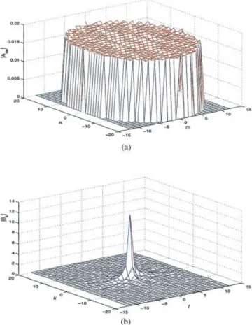
䡠 I, which prohibits its application to very large arrays. Therefore, the DFT-based acceleration algorithm is used in conjunction with FBM, which is based on using the DFT spectrum of currents to reduce computational complexity. As shown in Figure 2(a), a typical current distribution on array elements is quite different from the feed distribution, especially near the array boundary. Hence, to find the current distribution on the array and the input impedances of the elements accurately, one has to ana-lyze the complete array using rigorous numerical methods. How-ever, the DFT spectrum of practical array currents are very com-pact, as seen in Figure 2(b). Consequently, the selection of a few significant DFT terms from the DFT spectrum is sufficient to provide accurate results. These significant DFT terms are selected based on the criteria given in [11].
The DFT-based acceleration algorithm is actually well-suited for the fast and accurate analysis of rectangular arrays (freestand-ing and printed) [13–15]. Therefore, to implement this algorithm efficiently, the arrays shown in Figure 1 are mathematically ex-tended into a rectangular array with virtual elements as shown in Figure 3. All the virtual elements are located external to the array Figure 2 (a) Current amplitudes兩Anm兩, and (b) DFT spectrum of the
currents兩Bkl兩 for a uniformly excited 749-element elliptical printed dipole
array. The array parameters are (L, W)⫽ (0.30, 0.010), dx⫽ dy⫽
0.50,r⫽ 2.55, d ⫽ 0.060and (, ) ⫽ (0°, 0°). [Color figure can
be viewed in the online issue, which is available at www.interscience. wiley.com.]
Figure 3 In the extended array, decomposition of interaction elements in terms of strong and weak groups with respect to the pqthreceiving element.
The virtual elements are the dipoles (marked with red) located external to the array boundary. [Color figure can be viewed in the online issue, which is available at www.interscience.wiley.com.]
boundary. Then, similar to [13–15], this DFT-based acceleration algorithm is implemented. Briefly, the contributing elements in front of the receiving element are divided into “strong” and “weak” interaction groups (Fig. 3), such that
关Z 䡠 I兴pq⫽
冘
nm僆strongAnmZnm,pq⫹
冘
nm僆weakAnmZnm,pq. (6)
The number of elements which remain in the strong group is fixed and very small compared to the number of elements in the entire array, but contributions coming from this group assure the funda-mental accuracy of the method and, hence, are obtained in an exact element-by-element fashion. On the other hand, although contri-butions coming from the weak group provide only minor correc-tions, their evaluation without the acceleration algorithm would constitute the most time-consuming aspect of the MoM calcula-tions. Therefore, the weak region contribution to the pqthreceiving
element, given by Eweak共rpq兲 ⫽
冘
nm僆weak AnmZnm,pq, (7) is rewritten as Eweak共rpq兲 ⫽冘
k⫽⫺N N冘
l⫽⫺M M Bkl冘
nm僆weak Znm,pqe⫺jkx ndxe⫺jkymdye⫺j2共kn/ 2N⫹1兲e⫺j2共lm/ 2M⫹1兲 (8) by using the DFT expansion of the unknown coefficients Anm, which is expressed as Anm⫽ e⫺jkxndxe⫺jkymdy冘
k⫽⫺N N冘
l⫽⫺M M Bkle⫺j2共kn/ 2N⫹1兲e⫺j2共lm/ 2M⫹1兲, (9)with Bklbeing the coefficient of the kl
thDFT term. Using only the
important DFT terms [due to the compactness of the DFT spec-trum, as shown in Fig. 2(b)], which are a few but significant so that the accuracy is maintained, results in
Eweak共rpq兲 ⫽
冘
kl僆QBklCkl,pq, (10)
where Q denotes the selected DFT terms, and
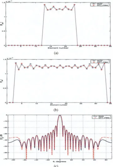
Figure 4 Comparison of the magnitude of induced current兩Anm兩 for the
(a) 2ndrow and (b) 11throws and (c) the radiation pattern obtained via
DFT-FBM and conventional MoM of a 901-element (35⫻ 35) elliptical, uniformly excited freestanding dipole array. The array parameters are (L,
W(radius))⫽ (0.40, 0.0010), dx⫽ 0.70, dy⫽ 0.40and (, ) ⫽ (0°,
0°). Size of the strong region⫽ 5 ⫻ 5. Number of DFT terms ⫽ 3. [Color figure can be viewed in the online issue, which is available at www. interscience.wiley.com.]
Figure 5 (a) Magnitude and (b) phase of the current amplitudes on the 5throw of a 709-element (31⫻ 31) circular, uniformly excited printed
dipole array. The array parameters are (L, W)⫽ (0.390, 0.010), dx⫽ dy⫽ 0.50,r⫽ 2.55, d ⫽ 0.060and (, ) ⫽ (30°, 0°). Size of the
strong region⫽ 3 ⫻ 3. The number of DFT terms ⫽ 5, and three basis functions per dipole are used. [Color figure can be viewed in the online issue, which is available at www.interscience.wiley.com.]
Ckl,pq⫽
冘
nm僆weakZnm,pqe⫺jkx
ndxe⫺jkymdye⫺j2共kn/ 2N⫹1兲e⫺j2共lm/ 2M⫹1兲. (11)
Ckl,pqin (11) denotes the contribution of the klthDFT term to the pqthreceiving element and can be calculated very efficiently in an
iterative fashion for the rectangularly contoured arrays, as demon-strated in [13–15].
On the other hand, the arrays we consider in this paper are irregularly contoured arrays and are extended to rectangularly contoured ones by introducing the virtual elements so that Eqs. (6)–(11) can be used. However, when using these equations, it should be assumed that currents on these elements are exactly zero (that is, Anm⫽ 0 for virtual elements). Therefore, in the evaluation of the strong region contributions, both the voltages on these elements and the mutual coupling between and with these elements are set to zero. In other words,
Vpq⫽ 0 if pq 僆 virtual element, (12) and
Znm,pq⫽ 0 if nm and/or pq 僆 virtual element. (13) Implementation of (12) and (13) will assure that Anm ⫽ 0 for
virtual elements. On the other hand, in the evaluation of the weak-region
con-tributions, such as the computation of (11), each Znm,pqbetween a virtual element and a real element, as well as each Znm,pqbetween two virtual elements, are identical to those between real elements (that is, they are now nonzero as opposed to (13)). Since the Anm values of virtual elements are now taken as zero in the computation of the Bkl values, utilization of nonzero Znm,pq values will not cause any problem if all DFT terms are employed. In reality, insignificant errors might occur due to the use of few DFT terms. However, that amount of error in the computation of contributions coming from the weak region will not affect the overall accuracy. 3. NUMERICAL RESULTS
To assess the accuracy and efficiency of this proposed approach for the analysis of irregularly contoured arrays, numerical results pertaining to both freestanding and printed dipole arrays are ob-tained and compared with the results obob-tained via conventional MoM. In all examples, the arrays are excited uniformly in ampli-tude so that Vpq⫽ 1 in (2) for each pq
thdipole.
In Figures 4(a) and 4(b), current amplitudes兩Anm兩 versus the element position on the 2ndand 11th rows are evaluated using
DFT-FBM and compared with the conventional MoM solution pertaining to a 901-element elliptical (the size of the corresponding rectangular array after introducing the virtual elements is 35⫻ 35), uniformly excited freestanding dipole array with dx⫽ 0.70and dy⫽ 0.40(with0being the free-space wavelength). The length
and radius of each dipole are 0.40and 0.0010, respectively. The elements are phased to radiate a beam in broadside direction, as shown in Figure 4(c). As seen from the figure, very good agree-ment is obtained using just three DFT coefficients and 5⫻ 5 strong regions (12 elements in forward and 12 elements in backward runs). Less than 2% error is achieved with just three iterations, and the elapsed CPU time for DFT-FBM is 0.17 sec, whereas it is 10.4 sec for the conventional MoM approach.
Figures 5(a) and 5(b) depict the magnitude and phase of current amplitudes versus element position on the 5th row of a
709-element circular (the size of the corresponding rectangular array after introducing the virtual elements is 31 ⫻ 31), uniformly excited printed dipole array on a 0.060thick substrate withr⫽ 2.55. Each dipole has a dimensions of (L, W) ⫽ (0.390, Figure 6 Comparison of the magnitude of induced current兩Anm兩 for the
(a) 4thand (b) 11throws obtained via DFT-FBM and conventional MoM
for a 749-element (41⫻ 25) elliptical, uniformly excited printed dipole array. The array parameters are (L, W)⫽ (0.390, 0.010), dx⫽ dy⫽
0.50,r⫽ 2.55, d ⫽ 0.060and (, ) ⫽ (0°, 0°). The size of the
strong region⫽ 3 ⫻ 3, the number of DFT terms ⫽ 5, and three basis functions per dipole are used. [Color figure can be viewed in the online issue, which is available at www.interscience.wiley.com.]
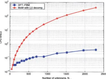
Figure 7 Comparison of CPU times for DFT-FBM and MoM with LU decomposition for printed dipole arrays. The array and the substrate pa-rameters are the same as the ones used in Figs. 5 and 6. [Color figure can be viewed in the online issue, which is available at www.interscience. wiley.com.]
0.010) and they are spaced from each other by distances dx⫽
dy⫽ 0.50 in the xˆ and yˆ directions, respectively. The elements
are phased to radiate a beam in the (, ) ⫽ (30°, 0°). For this example, the size of the strong region is 3⫻ 3 (four elements in forward and four elements in backward runs), and five DFT terms are used. Again a residual error less than 1.5% error is achieved with three iterations. The elapsed CPU time for DFT-FBM is 0.625 sec for this example. Using a conventional MoM approach requires a CPU time of 595.9 sec. Note that three basis functions per dipole is used for this example.
As a third example, a 749-element printed dipole with an elliptical boundary is considered (the size of the corresponding rectangular array after introducing the virtual elements is 41⫻ 25). The array and the substrate parameters are the same as the previous example. Figures 6(a) and 6(b) show a comparison of the magni-tude of induced current兩Anm兩 for the 4th and 11throws, respec-tively, obtained via DFT-FBM and conventional MoM. The size of the strong region, the number of DFT terms, and the residual error are also the same as the previous example.
As seen in all examples, very good agreement between the DFT-FBM and conventional MoM results has been achieved, thereby establishing confidence in the present DFT-FBM ap-proach. Finally, the CPU times of the DFT-FBM approach and MoM with LU decomposition is compared in Figure 7 for a printed dipole array whose parameters are the same as the ones used in the aforementioned numerical results. As illustrated in the figure, the required CPU time for the DFT-FBM approach is very small compared to that required in the conventional MoM, especially when Ntot is very large.
4. DISCUSSIONS AND CONCLUSIONS
Efficient and accurate analysis of electrically large, planar, peri-odic, finite (phased), arbitrarily contoured arrays of both freestand-ing and printed dipoles has been presented by introducfreestand-ing the virtual-element concept. Both the computational complexity and the memory-storage requirements are O(Ntot). The efficiency and accuracy of the method have been demonstrated by numerical results in the form of current distributions on and far-field radiation patterns of various arrays with irregular contours.
REFERENCES
1. R.F. Harrington, Field computation by moment methods, IEEE Press, Piscataway, NJ, 1993.
2. A. Ishimaru, R.J. Coe, G.E. Miller, and V.P. Green, Finite periodic approach to large scanning array problems, IEEE Trans Antennas Propagat 31 (1985), 54 –59.
3. H.-T. Chou, Extension of the forward-backward method using spectral acceleration for the fast analysis of large array problems, IEE Proc Microwave Antennas Propagat 147 (2000), 167–172.
4. N. Engheta, W.D. Murphy, V. Rokhlin, and M.S. Vassiliou, The fast multipole method (FMM) for electromagnetic scattering problems, IEEE Trans Antennas Propagat 40 (1992), 634 – 641.
5. X.Q. Sheng, J.-M. Jin, J. Song, W.C. Chew, and C.-C. Lu, Solution of combined-field integral equation using multilevel fast multipole algo-rithm for scattering by homogeneous bodies, IEEE Trans Antennas Propagat 46 (1998), 1718 –1726.
6. Y. Zhuang, K.-L. Wu, C. Wu, and J. Litva, A combined full-wave CG-FFT method for rigorous analysis of large microstrip antenna arrays, IEEE Trans Antennas Propagat 44 (1996), 102–109. 7. A.K. Skrivervik and J.R. Mosig, Finite phased array of microstrip
patch antennas: the infinite array approach, IEEE Trans Antennas Propagat 40 (1992), 579 –582.
8. O¨ .A. Civi, P.H. Pathak, H.-T. Chou, and P. Nepa, A hybrid uniform geometrical theory of diffraction-moment method for the efficient
analysis of electromagnetic radiation/scattering from large finite planar arrays, Radio Science 35 (2000), 607– 620.
9. A. Neto, S. Maci, G. Vecchi, and M. Sabbadini, A truncated Floquet wave diffraction method for the full-wave analysis of large phased arrays, part 2: generalization to 3D cases, IEEE Trans Antennas Propagat 48 (2000), 601– 611.
10. O¨ .A. Civi, V.B. Ertu¨rk, P.H. Pathak, P. Janpugdee, and H.-T. Chou, A hybrid UTD-MoM approach for the efficient analysis of radiation/ scattering from large, printed finite phased arrays, 2001 IEEE AP-S International Symposium and USNC/URSI Meeting, Boston, MA, 806 – 809.
11. H.-T. Chou, H.-K. Ho, P.H. Pathak, P. Nepa, and O¨ .A. Civi, Efficient hybrid discrete Fourier transform-moment method for fast analysis of large rectangular arrays, IEE Proc Microwave Antennas Propagat 149 (2002), 1– 6.
12. H.-T. Chou, H.-K. Ho, O¨ .A. Civi, and V.B. Ertu¨rk, Applications of hybrid discrete Fourier transform-moment method to the fast analysis of large rectangular dipole arrays printed on a thin grounded dielectric substrate, Microwave Opt Technol Lett 34 (2002), 203–207. 13. H.-T. Chou and H.-K. Ho, Implementation of a forward-backward
procedure for the fast analysis of electromagnetic radiation/scattering from two-dimensional large phased arrays, IEEE Trans Antennas Propagat 52 (2004), 388 –396.
14. O¨ .A. Civi, Extension of forward backward method with DFT based acceleration algorithm for the efficient analysis of radiation/scattering from large finite printed dipole arrays, Microwave Opt Technol Lett 37 (2003), 20 –26.
15. V.B. Ertu¨rk and H.-T. Chou, Efficient analysis of large phased arrays using iterative MoM with DFT based acceleration algorithm, Micro-wave Opt Technol Lett 39 (2003), 89 –94.
16. E. Martini, A. Toccafondi, S. Maci, and R. Tiberio, Floquet wave-based diffraction approach for irregularly contoured planar phased arrays, IEEE Antennas and Wireless Propagat Letters 2 (2003), 246 – 249.
17. S. Barkeshli, P.H. Pathak, and M. Marin, An asymptotic closed-form microstrip surface Green’s function for the efficient moment method analysis of mutual coupling in microstrip antennas, IEEE Trans An-tennas Propagat 38 (1990), 1374 –1383.
© 2005 Wiley Periodicals, Inc.
BROADBAND DUAL-POLARIZED
PROXIMITY COUPLED CIRCULAR
PATCH ANTENNA
S. Gao and A. Sambell
School of Engineering and Technology Northumbria University
Newcastle Upon Tyne, Northern 8ST, United Kingdom
Received 20 April 2005
ABSTRACT: This paper presents the design and results of a novel
broadband dual-polarized circular patch antenna. The antenna is fed by microstrip lines through proximity coupling, and H-shaped slots are cut in the ground plane below the feed lines for enhancing the coupling be-tween the patch and the feed lines. By using only a single circular mi-crostrip patch, the prototype antenna yields bandwidth of 21.5% and 25.9% at the input ports 1 and 2, respectively. The isolation between two input ports is below⫺30 dB across the bandwidth. Good broadside radiation patterns are observed, and the cross-polar levels are below
⫺20 dB at both E- and H-planes. Due to its simple structure, it is easy
to form arrays by using this antenna as an element. © 2005 Wiley
Peri-odicals, Inc. Microwave Opt Technol Lett 47: 298 –302, 2005; Published online in Wiley InterScience (www.interscience.wiley.com). DOI 10.1002/mop.21151