ANALYSIS AND DESIGN OF BROADCAST
TOWER ANTENNA SYSTEMS
a thesis submitted to
the graduate school of engineering and science
of bilkent university
in partial fulfillment of the requirements for
the degree of
master of science
in
electrical and electronics engineering
By
Abdul Ali
December, 2014
Analysis and Design of Broadcast Tower Antenna Systems By Abdul Ali
December, 2014
We certify that we have read this thesis and that in our opinion it is fully adequate, in scope and in quality, as a thesis for the degree of Master of Science.
Prof. Dr. Ayhan Altınta¸s(Advisor)
Assoc. Prof. Dr. Vakur B. Ert¨urk
Assist. Prof. Dr. Satılmı¸s Topcu
Approved for the Graduate School of Engineering and Science:
ABSTRACT
ANALYSIS AND DESIGN OF BROADCAST TOWER
ANTENNA SYSTEMS
Abdul Ali
M.S. in Electrical and Electronics Engineering Advisor: Prof. Dr. Ayhan Altınta¸s
December, 2014
In broadcasting, the coverage and interference requirements of antennas are des-ignated in terms of Effective Radiated Power (ERP), tower location and height, and antenna patterns. When antennas are tailored to satisfy the requirements, transmitter powers, cable losses, and phase adjustments for antenna elements must be taken into account in addition to the parasitic effect of the supporting and nearby towers on characteristics of antenna.
Digital video and audio broadcasting requires antennas to be at least 95 % effi-cient, wideband, low weight and high gain with enhanced radiation performance. For this reason many wire and planar antennas have been designed to meet the requirement of Digital Video Broadcasting-Terrestrial (DVB-T) and Terrestrial-Digital Audio Broadcasting (T-DAB).
We used a tool NEC (Numerical Electromagnetic Code) to model antenna on top of a tower structure. Simulation results for parasitic effect of the tower on characteristics of antenna such as impedance, return loss, gain, front-to-back ratio and radiation patterns are reported. In addition, the effect of nearby tower on antenna characteristics is studied. We designed a broadband antenna in the UHF (470 - 860 MHz) band that works for both digital and analog TV with return loss ≥10 dB, fractional bandwidth of 85% and gain at center frequency 12.5 dB. The ERP is calculated by mounting the antenna at each face of the tower to give a satisfactory coverage to a region around the antenna.
Moreover, the design of a transmitter antenna for DVB-T and T-DAB is pre-sented with Stacked Suspended Plate Antenna (SSPA) structure. Considering the similar products in the world, antennas have been designed in (174-254)MHz for DVB-T and (174-230)MHz for T-DAB with horizontal polarization and return
iv
loss ≥ 10 dB. The antenna gives an average gain of 8.5 dB and cross polarization isolation is 31 dB. Contrary to conventional dipole structures, we have employed SSPA structure with two plates for wideband matching and design flexibility. Radiating primary plate has been excited by novel wideband modified inverted L-type probe in a capacitively coupled manner. Vertical plate between primary plate and ground plane also provides wideband matching and adjustment of half-power beam width properly. Parasitic secondary plate has been used for further matching and tuning. Together with the parametric study of designed antenna, simulation and measurement results for the input impedance, S11, gain and
¨
OZET
YAYIN KULE ANTEN S˙ISTEMLER˙IN˙IN C
¸ ¨
OZ ¨
UMLEME
VE TASARIMI
Abdul Ali
Elektrik ve Elektronik M¨uhendisli˘gi, Y¨uksek Lisans Tez Danı¸smanı: Prof. Dr. Ayhan Altınta¸s
Aralık, 2014
Radyo ve TV yayınlarında, antenlerin kapsama ve giri¸simi ile ilgili ko¸sullar, Etkin Yayılan G¨u¸c (EYG), kule konumu ve y¨uksekli˘gi ile anten ¨or¨unt¨us¨u ¨uzerinden tanımlanmaktadır. Antenler bu ko¸sulları sa˘glayacak hale getirilirken, verici g¨u¸cleri, kablo kayıpları ve anten elemanları i¸cin faz ayarlamalarının, destekleyici ve civardaki kulelerin anten nitelikleri ¨uzerindeki yayın bozucu etkileri ile birlikte g¨oz ¨on¨unde bulundurulması gerekmektedir.
Sayısal g¨or¨unt¨u ve ses yayınında antenlerin en az %95 verimlili˘ge, geni¸s band aralı˘gına, d¨u¸s¨uk bir a˘gırlı˘ga, y¨uksek kazanca ve arttırılmı¸s bir ı¸sınım perfor-mansına sahip olması istenmektedir. Bu nedenle, ¸cubuk ve d¨uzlemsel antenler, Sayısal Karasal Video Yayıncılı˘gı (DVB-T) ve Sayısal Karasal Ses Yayıncılı˘gı (T-DAB)’nın ¨ong¨ord¨u˘g¨u ko¸sulları sa˘glamak ¨uzere tasarlanmı¸stır.
Antenin kule ¨uzerindeki modellemeleri i¸cin NEC (Numerical Electromagnetic Code) programı kullanılmı¸stır. Kulenin, antenin empedans, geri d¨on¨u¸s kaybı, kazan¸c, ¨on-arka oranı ve ı¸sınım ¨or¨unt¨us¨u gibi ¨ozellikleri ¨uzerindeki bozucu etk-ileri incelenmi¸stir. Ayrıca, civarda bulunabilecek bir kulenin anten ¨ozellikleri ¨
uzerinde yarattı˘gı etki de ¸calı¸sılmı¸stır. UHF (470-860 MHz) bandında, sayısal ve analog TV yayınları i¸cin, geri d¨on¨u¸s kaybı 10 dB’den daha d¨u¸s¨uk, %85 kısmi band aralı˘gına sahip ve merkez frekansta kazancı 12.5 dB olan bir anten tasar-lanmı¸stır. C¸ evredeki bir alana yeterli seviyede bir kapsama sa˘glamak amacıyla anten, kulenin her bir y¨uz¨une konumlandırılarak EYG hesaplanmı¸stır.
Tezde, bunlardan ayrı olarak, DVB-T ve T-DAB i¸cin, Yı˘gınlamı¸s Asılı Plaka Anten (YAPA) yapısında bir verici anten tasarımı da sunulmaktadır. D¨unyadaki benzer tipte ¨ur¨unleri de g¨oz ¨on¨unde bulundurarak, antenler, DVB-T i¸cin 174-254 MHz ve T-DAB i¸cin 174-230 MHz arasında, yatay kutuplanma ve 10 dB’den
vi
daha iyi geri d¨on¨u¸s kaybı i¸cin tasarlanmı¸stır. Antenin ortalama kazancı 8.5 dB olup, ¸capraz kutuplanma yalıtımı 31 dB olarak elde edilmi¸stir. Geleneksel dipol yapılarının aksine, geni¸s bandlı uyumlandırma ve tasarım esnekli˘gi a¸cısından iki plakalı YAPA yapısı kullanılmı¸stır. I¸sıma yapan birinci plaka, yeni bir geni¸s bandlı de˘gi¸stirilmi¸s ters L-tipi prob yapısıyla kapasitif ba˘gla¸sıklık ile uyarılmı¸stır. Birinci plaka ve toprak d¨uzlemi arasındaki dikey plaka da geni¸s bandlı uyumlandırma ve yarı-g¨u¸c ı¸sın geni¸sli˘gi sa˘glamaktadır. Bozucu ikincil plaka uyumlandırma ve ince ayarlama amacıyla kullanılmı¸stır. Tasarlanan antenin parametrik ¸calı¸sması ile beraber, giri¸s empedansı, S11, kazan¸c ve ı¸sınım ¨or¨unt¨uleri i¸cin benzetim ve ¨ol¸c¨um
Acknowledgement
I would like to express my heartfelt appreciation and gratitude to my super-visor Prof. Dr. Ayhan Altınta¸s for the patient guidance, encouragement and advice he has provided throughout my time as his student. I have been so lucky to have a supervisor who cared so much about my work, and who responded to my questions and queries all of the time. Throughout MS research, he was so polite, friendly, and never become angry at me.
I would like to thank Assoc. Prof. Dr. Vakur B. Ert¨urk for not only being member of the jury, reading and reviewing my thesis but also for the help he provided in courses taken from him. I would to thank Assist. Prof. Dr. Satılmı¸s Topcu for being member of the jury, evaluating my Ms thesis.
I would also like to thank Dr. Mehmet C¸ ıydem for his help and guidance to produce such a nice research work.
Finally, I would like to thank my family and friends for their support, co-operation and patience.
Contents
1 Introduction 1
2 Theoretical Background 5
2.1 Characteristics of Broadcast Antennas . . . 6
2.1.1 Polarization . . . 6
2.1.2 VSWR and Return Loss . . . 7
2.1.3 Bandwidth . . . 7
2.1.4 Beamwidth . . . 8
2.1.5 Gain . . . 8
2.1.6 Effective Radiated Power . . . 8
2.2 Tower Structure . . . 10
2.3 Stacked Suspended Plate Antenna . . . 10
CONTENTS ix
3.2 Broadband Dipole Antenna Simulation . . . 17
4 Broadband Panel Antenna Design in 4nec2 23 4.1 Broadband dipole Array design . . . 23
4.1.1 Feeding Mechanism . . . 25
4.2 Effect of the Back Plane . . . 28
4.2.1 Far-field Patterns . . . 30
4.2.2 Input Impedance . . . 31
4.2.3 Return Loss . . . 32
4.2.4 Gain and Front-To-Back Ratio . . . 33
5 Parasitic effect of Antenna Towers 36 5.1 Tower Structure in 4nec2 . . . 36
5.2 Antenna with Tower in 4nec2 . . . 38
5.3 Effect of the Tower on Antenna Characteristics . . . 39
5.3.1 Input Impedance . . . 39
5.3.2 Return Loss . . . 40
5.3.3 Gain and Front-To-Back Ratio . . . 41
5.3.4 Far-field Patterns . . . 43
CONTENTS x
5.4.1 Far-field Patterns . . . 46
5.4.2 Input Impedance and Return Loss . . . 46
5.4.3 Gain and Front-to-Back Ratio . . . 53
5.5 Effective Radiated Power . . . 56
6 Design of Stacked Suspended Plate Antennas for Broadcasting 59 6.1 Antenna Geometry . . . 59
6.2 Simulation and Measurement Results . . . 62
6.2.1 Input impedance and Return Loss . . . 63
6.2.2 Gain and Radiation Patterns . . . 65
6.3 Parametric Study . . . 69
6.3.1 The Height of Primary Plate . . . 70
6.3.2 The Height of Secondary Plate . . . 72
6.3.3 Position of the Vertical Plate . . . 74
6.3.4 Length of the Edge . . . 77
7 Conclusion 80
List of Figures
2.1 Lattice model of tower. . . 9
2.2 Structure of SPA . . . 11
2.3 Rectangular plate with L-strip proximity feeding structure . . . . 12
2.4 Feeding plate with probe feeding structure . . . 12
2.5 Structure of Proposed SSPA . . . 13
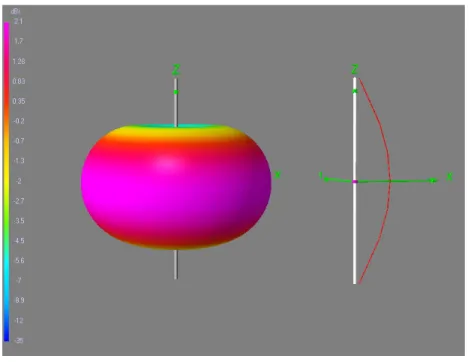
3.1 3D radiation pattern and current distribution of ˆz directed half-wave dipole . . . 17
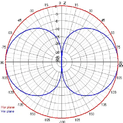
3.2 Far field vertical and horizontal patterns of ˆz directed half-wave dipole . . . 19
3.3 3D view of half wave cylindrical dipole . . . 19
3.4 Input resistances of half wave wire and cylindrical dipole . . . 20
3.5 Input reactances of half wave wire and cylindrical dipole . . . 20
3.6 Reflection coefficient of half wave wire and cylindrical dipole . . . 21
LIST OF FIGURES xii
4.1 Front view of broadband panel antenna . . . 24
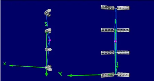
4.2 3D structure of the antenna in 4nec2, side view & front view . . . 25
4.3 Input impedance of the dipole array . . . 26
4.4 Reflection coefficient of the dipole array . . . 27
4.5 Gain of the dipole array . . . 27
4.6 3D structure and pattern of the dipole array . . . 28
4.7 Dipole array with back Plane, front and side view . . . 29
4.8 Far-field pattern of dipole array with back plane . . . 30
4.9 Magnitude of |Zin| for dipole array . . . 31
4.10 Phase of Zin for the dipole array . . . 32
4.11 Reflection coefficient of dipole array . . . 33
4.12 Gain of the dipole array . . . 34
4.13 Front-to-back ratio of the dipole array . . . 35
5.1 Tower structure in 4nec2 . . . 37
5.2 Tower structure along with antenna in 4nec2 . . . 38
5.3 Effect of the tower on magnitude of Zin of the antenna . . . 39
5.4 Effect of the tower on phase of Zin of the antenna . . . 40
5.5 Effect of the tower on reflection coefficient of the antenna . . . 41
LIST OF FIGURES xiii
5.7 Effect of the tower on the front-to-back ratio of the antenna . . . 42 5.8 Effect of the tower on the vertical pattern of antenna . . . 43 5.9 Effect of the tower on the horizontal pattern of antenna . . . 44 5.10 Structure of the two towers, when there is no antenna on the nearby
tower . . . 45 5.11 Structure of the two towers, when there is an antenna on the nearby
tower . . . 45 5.12 Effect of the nearby tower on the vertical pattern at d=50m . . . 47 5.13 Effect of the nearby tower on the vertical pattern at d=100m . . . 47 5.14 Effect of the nearby tower on the vertical pattern at d=150m . . . 48 5.15 Effect of the nearby tower on the vertical pattern at d=200m . . . 48 5.16 Effect of the nearby tower on the horizontal pattern at d=50m . . 49 5.17 Effect of the nearby tower on the horizontal pattern at d=100m . 49 5.18 Effect of the nearby tower on the horizontal pattern at d=150m . 50 5.19 Effect of the nearby tower on the horizontal pattern at d=200m . 50 5.20 Effect of the nearby tower on S11 of the antenna when d=5m . . . 51
5.21 Effect of the nearby tower on S11 of the antenna when d=9m . . . 51
5.22 Effect of the nearby tower on S11 of the antenna when d=14m . . 52
LIST OF FIGURES xiv
5.24 Effect on the gain of the antenna in case of nearby tower without
an antenna . . . 53
5.25 Effect on the gain of the antenna in case of a tower with an antenna 54 5.26 Effect on the F/B ratio of the antenna in case of a tower without an antenna . . . 55
5.27 Effect on F/B ratio of the antenna in case of a tower with an antenna 55 5.28 Power budget of the antenna . . . 57
5.29 Horizontal pattern of antenna . . . 58
6.1 Geometry of SSPA antenna . . . 60
6.2 Geometry of SSPA antenna, front view . . . 61
6.3 Fabricated SSPA antenna . . . 62
6.4 Geometry of SSPA antenna in CST . . . 62
6.5 Input resistance of the SSPA antenna . . . 63
6.6 Input reactance of the SSPA antenna . . . 64
6.7 Reflection coefficient of the SSPA antenna . . . 64
6.8 Gain of the SSPA antenna . . . 65
6.9 3D pattern of the SSPA antenna in CST . . . 66 6.10 Co-polarized and cross-polarized radiation patterns in the E plane 67 6.11 Co-polarized and cross-polarized radiation patterns in the H plane 68
LIST OF FIGURES xv
6.13 Effect of the height of primary plate on input resistance . . . 69
6.14 Effect of the height of primary plate on input reactance . . . 70
6.15 Effect of the height of primary plate on reflection coefficient . . . 71
6.16 Effect of the height of primary plate on gain . . . 71
6.17 Effect of the height of secondary plate on input resistance . . . 72
6.18 Effect of the height of secondary plate on input reactance . . . 73
6.19 Effect of the height of the secondary plate on reflection coefficient 73 6.20 Effect of the height of secondary plate on gain . . . 74
6.21 Effect of the vertical plate position on input resistance . . . 75
6.22 Effect of the vertical plate position on input reactance . . . 75
6.23 Effect of the vertical plate position on reflection coefficient . . . . 76
6.24 Effect of the vertical plate position on gain . . . 76
6.25 Effect of Le on input resistance . . . 77
6.26 Effect of Le on input reactance . . . 78
6.27 Effect of Le on reflection coefficient . . . 78
List of Tables
3.1 Nec Design Rules . . . 16
4.1 Characteristics of Panel Antenna . . . 24 4.2 4nec2 results compared with Kathrein antenna at resonance
fre-quency . . . 30
5.1 ERP with Different Configuration . . . 57
Chapter 1
Introduction
Digital Video Broadcasting Terrestrial (DVB-T) and Terrestrial Digital Audio Broadcasting (T-DAB) opened a new door of research in many fields. For in-stance, communication researchers are trying to make efficient coding techniques and devices for the optimal transmission of data. In RF, the focus is on making efficient amplifiers and electronic circuits that are less noisy. In electromagnetics and antennas, the goal is to make smart antennas with wider bandwidth, higher gain and front-to-back ratio, large return loss and half power beamwidth to give optimal coverage to a particular region. Many antennas have been designed in this regard for instance, dipole antenna, folded dipole, Yagi-Uda antenna, log-periodic antenna, quarter wave monopole antenna and spiral antenna [1]. Also, many planar antennas are mentioned in literature for the same purpose.
In broadcasting, when antennas are mounted on top of a tower, it is impor-tant to see whether properties of antennas such as patterns, impedance, return loss, gain and front-to-back ratio are affected by the tower. It is also necessary to see the effect of nearby towers on the radiation characteristics of transmit-ting antennas. In [2], an effort is made to install UHF antennas on an existransmit-ting tower containing VHF antennas and mutual interference is studied. But, it is unclear whether the tower has effect on the characteristics of the UHF antenna. Furthermore, the effect of tower on the radiation pattern depends on frequency,
polarization azimuth angle and elevation angle in the near field [3].
Planar antennas such as microstrip plate/patch antennas have attracted many researchers due to their low profile, light weight, ease of fabrication and integra-tion, low cost, conformability and versatility. However, they have some major disadvantages, which make them non-suitable for practical broadcasting applica-tions for instance, small bandwidth and poor radiation performance [4]. Many techniques have been used to improve the impedance bandwidth and radiation performance of microstrip plate antennas. It includes varying shapes of plates, adding parasitic plates and shorting pins, use of low permittivity substrates and different feeding mechanism [4, 5].
In [4], impedance bandwidth is broadened by means of using a thick dielec-tric substrate, but it also degrades the radiation efficiency due to generation of surface waves [5]. Low dielectric substrate helps in suppressing surface waves. The bandwidth can also be increased by changing the shape of the antennas for instance, use of E shaped plates, slotted antennas and combination of slotted and E shaped plate antennas. A half U slot and half E shaped plate antennas are examples of such combination [6, 7]. Probe feeding mechanism is utilized to enhance the bandwidth of the stacked plate antennas [8]. Despite of giving good impedance bandwidth by [4], [6], [7] and [8], it gives poor radiation performance in the sense of cross polarization levels. Single and multiple port feeding struc-tures are also used to make the bandwidth wider along with acceptable radiation efficiency [9–16].
Works in [9, 10] address the radiation performance of a single port center fed patch antennas, while [12] uses shorting strips and slots for the same purpose but again the impedance bandwidth is affected here. Four port capacitive probe feeding is applied in [14] to get broad bandwidth and radiation performance, but the coupling between the input ports degrades the return loss. The coupling is reduced by using multiple shorting pins. In [16], single-feed, circularly polarized (CP) stacked plate antenna is used for UHF RFID reader applications. Dual L-shaped strips or single modified L-shaped strip that employs electromagnetic
in [11, 13, 15].
Furthermore, in [17–19] the impedance bandwidth is improved by means of non-planar radiating plate and making the middle portion of probe feed plate antenna concaved to form a V-like structure to get a bandwidth of about 60%. However, this method suffers from bad radiation pattern performance, which is further improved in [19] by using tapered down feeding strip mechanism. It gives dipole like radiation pattern.
In this thesis, we investigated the parasitic effect of tower structure on charac-teristics of broadcast antenna, in terms of input impedance, return loss, gain and front- to-back ratio. We used 4nec2 (numerical electromagnetic code) software to simulate some wire antennas such as dipole and dipole array together with the tower structure. Then, we mounted antenna arrays on top of a tower to observe parasitic effect of it on antenna properties. The effect of a nearby tower on ra-diation characteristics of transmitting antenna is presented. We also calculated the Effective Radiated Power (ERP) that would be needed to cover a particular area.
Furthermore, we designed a stacked suspended plate antenna (SSPA) for digital video and audio broadcasting. The designed SSPA consists of a novel wideband modified inverted L-Type probe feeding mechanism to excite the primary radi-ating plate in a capacitively coupled manner. Wideband matching is achieved through determination of the best suitable positions of suspended plates. A ver-tical plate between primary plate and ground plane that does not touch either of them, is used for further matching and beam width adjustment. The designed antenna works for both DVB-T and T-DAB applications, with frequency band (174-230) MHz. The antenna is fabricated to verify the simulation results. In the entire band the return loss is equal or greater than 10 dB with average gain of 8.5 dB.
In Chapter 2, we discuss some important characteristics of antennas in terms of broadcasting such as polarization, VSWR, return loss, bandwidth, beamwidth,
gain and effective radiated power(ERP). Tower structure in metal grid configu-ration for broadcasting is briefly introduced. Then, at the end of the chapter, suspended plate antenna, probe-fed, L-proximity fed and stacked suspended an-tenna are shortly discussed.
In Chapter 3, a short introduction about 4nec2 software and its four main editors (Notepad Editor, Nec Editor, Geometry Editor and Nec Editor New) are presented. Some features and design rules of 4nec2 are concisely discussed. To get familiarized with 4nec2, a simple wire and a cylindrical dipole are compared in terms of input impedance, bandwidth and gain.
In Chapter 4, a broadband antenna is designed in 4nec2 in UHF band. Feeding mechanism to feed all elements of the antenna with a single source is discussed. The effect of back plane on antenna properties are discussed. Gain, return loss, front-to-back ratio and far-field patterns are compared with and without the back plane.
In Chapter 5, information about simulation of metal grid tower construction and parasitic effect of a tower on antenna characteristics are presented. The antenna designed in Chapter 4 is mounted on top of a tower to see its effect on impedance, return loss, gain and front-to-back ratio of antenna. Effect of nearby tower on antenna characteristics is presented.
In Chapter 6, stacked suspended antenna is designed in VHF band for DVB-T and T-DAB applications in CST Microwave Studior. The antenna geometry is
presented, followed by simulation and measured results. Parametric study of the antenna is also presented by monitoring input impedance, return loss and gain.
Finally, Chapter 7 summarizes the whole thesis work. Simulations and mea-surements are discussed precisely. Furthermore, future work about antennas for broadcasting are briefly discussed.
Chapter 2
Theoretical Background
The transmitting antenna is the source of radiating electromagnetic energy/power into air. To radiate power in a particular direction may require antenna systems that include antenna elements and matching networks. At low frequencies, the wavelength λ is long and antennas can be made of metal wires. As the frequency increases to or beyond VHF, specialized antenna systems are required for high directivity, gain and bandwidth.
The half-wave dipole is the basic form of antenna and it can be made using a wire or a cylindrical tube that is half wavelength long. The half wave dipole has a radiation resistance of about 73Ω. The dipole arms can be bent to form a V like structure, where the impedance varies with the V angle [1]. Impedance decreases by decreasing V angle. In broadcasting, the dipole antenna with some modification is utilized to meet the requirement of applications for instance, Yagi-Uda arrays for the reception. DVB-T and T-DAB require the VSWR to be ≤1.1 [15]. In this regard, researchers are focusing on the dimensions and properties of wires, planar (microstrip antennas) and non-planar antennas.
2.1
Characteristics of Broadcast Antennas
A broadcasting antenna has many characteristics that are important for broadcast engineer, for example polarization, return loss, gain, bandwidth, beamwidth and effective radiated power (ERP). In the following, these characteristics are defined and discussed.
2.1.1
Polarization
Polarization is defined as the orientation of the propagating electric field. In broadcasting, when the radiated electric field is parallel to ground, then it is hor-izontal polarization and similarly, when it is perpendicular to the ground, then it is vertical polarization. If radiated electric field has both vertical and horizontal component with the same magnitude and phase difference of 90o then, it is called circular polarization since the E-field vector rotates with constant magnitude. LHCP (left hand circular polarization) and RHCP (right hand circular polar-ization) are special cases of circular polarization defined by the right hand rule. If radiated E -field has both components with magnitude and phase differences, then the wave has elliptical polarization.
In case of dipole antenna for broadcasting application, the polarization can be set by the dipole orientation for instance, a horizontally oriented dipole will radiate a wave with the horizontal polarization and the same goes for the vertical polarization. Vertically polarized wave follows multipath propagation through numerous reflective vertical elements in nature [20]. The vertical polarization is not a best option for television broadcasting as it undergoes more reflection than horizontal polarization which creates ghosts in analog broadcasting. For digital or analogue television or radio signal broadcasting, if large area is to be occupied or covered by one transmitter then horizontal polarization may be the best alternative and vertical polarization is most often used when it is desired to radiate a digital radio signal such as widely distributed mobile units [20].
Different polarizations may be utilized to reduce co-channel and adjacent chnel interferences. Both horizontal and circular polarization are suitable for an-tennas that can be installed on top of a tower [1].
2.1.2
VSWR and Return Loss
A transmission line acts as a medium that carries energy to feed the antenna. When a source power is connected to the transmission line, then, the incident power gets reflected from many points in transmission line, from mismatch at an-tenna and transmission line interface. The reflected wave combines with incident wave to form a standing wave that have periodic maximums and minimums. The ratio of maximum to minimum value of voltage wave gives the VSWR defined as:
V SW R = Vmax Vmin
(2.1) In broadcasting high value of VSWR is undesirable as it contributes to aural distortion, short term echoes, reduction in transmission line efficiency and visible ghost [1]. Reflection coefficient shows the amount of energy reflected from the antenna and it has a magnitude related to VSWR given by,
|Γ| = V SW R − 1
V SW R + 1 (2.2) and return loss in dB is given by
RL(dB) = −20log|Γ| (2.3) For antenna a good match is considered when the return loss≥10dB or in terms of VSWR<2.
2.1.3
Bandwidth
Bandwidth shows the range of frequencies at which antenna gives acceptable performance. Typically, bandwidth is defined as the frequency range where the RL≥10dB or VSWR<2. In communication systems, VSWR of less than 1.2
is acceptable within operational bandwidth of radiating signal and in modern broadcast systems VSWR of 1.1 or less is acceptable [1].
The impedance bandwidth of antenna depends on the variation of impedance with frequency, since the reflection coefficient is determined by the impedance.
2.1.4
Beamwidth
Half-power beamwidth is the angular width of main beam where the maximum directivity drops by 50%, wider beamwidth covers more area.
2.1.5
Gain
Gain and directivity shows how well energy is concentrated in a particular direc-tion. Directivity is the ratio of radiated power density in a given direction to that of isotropic source, whereas the gain is defined as the measure of field intensity in a given direction by a fixed input power to the antenna [1]. Therefore, gain combines the directivity with antenna efficiency.
The gain of an array describes the increase in radiated signal in the main radiating direction, which is produced by reducing radiation in all other direction other than main beam [20]. The gain of the antenna is related to beamwidth. The gain can be increased by narrowing the beamwidth. In broadcasting, gain is used as a figure of merit.
2.1.6
Effective Radiated Power
In antenna systems, Effective Radiated Power (ERP) is a standardized theoretical measurement of radio frequency (RF) energy and is determined by subtracting
system losses and adding system gains in dB scale. The ERP is given by
ERP (dB) = T P O + Gantenna− System Losses (2.4)
ERP takes into consideration transmitter power output (TPO) and transmission line attenuation [1]. In other words ERP is the product of the power supplied to the antenna and gain of the antenna with respect to a half wave dipole antenna. Another term used in broadcasting is effective isotropic radiated power (EIRP), which is the product of the power supplied to the antenna and gain of the antenna with respect to an isotropic radiator [21]. Usually, ERP is specified for covering a certain area around the transmitter. Then, the broadcasting engineer choses the antenna with specific gain and transmitter power output to satisfy the ERP requirement.
Figure 2.1: Lattice model of tower[21] .
2.2
Tower Structure
The scope of this study is limited to transmitting tower acting as a supporting structure. Several configurations of tower structure are available. We will discuss lattice model of tower only, since we are interested to see its parasitic effect on antenna characteristics. Figure 2.1, shows lattice model of tower.
Lattice configuration is more useful and antennas can be mounted on top of it as it takes into account the effect of wind-load. It has a crossbar structure that uses wires of same radius for the whole structure [22]. The cross-section can be triangular, square and hexagonal. A triangular tower can be modeled with three legs interconnected with multiple horizontal ring girth after intermediate height depending on the total height of the tower [22]. Similarly, a four face or square tower can be modeled with four legs. Antenna can be mounted at each face of the tower.
There are number of precautions and design rules that must be taken into consideration before designing a real world tower. For instance, wind load, height, icing, number of panels to mount and future loading [23]. In our case, we modeled tower as a parasitic element, to see its effect on the characteristics of the antenna. We used 4nec2 software to model the towers.
2.3
Stacked Suspended Plate Antenna
DVB-T, T-DAB and wireless communication require antennas to be small in size, wideband, high gain and with enhanced radiation performance [4]. However, planar antennas such as microstrip antennas have major drawbacks for instance, small bandwidth and poor radiation performance in the sense of cross-polarization isolation which make them non-suitable for practical applications [4].
Figure 2.2: Structure of SPA[4] .
plate, feeding mechanism and low permittivity material for support. The struc-ture of the antenna is given in Figure 2.2. The material for support is usually foam with permittivity 1.07. The height of feeding plate from the ground plane is denoted by “h”. Its value lies in between 0.03λ to 0.12λ. The value of “h”, separation between the radiating plate and ground plane are determined by the detailed parametric study of the SPA. The antenna is fed by coaxial probe or probe feeding structure [4].
The main radiator is excited through electromagnetic coupling. However, feed-ing probe of long length introduce large inductance which degrades impedance matching. There are several ways to improve the matching discussed in introduc-tory part. Our focus here is on modified inverted L-strip.
Figure 2.3 illustrates a rectangular plate antenna with L-proximity feeding structure. Impedance matching is achieved with the dimensions of L-section proximity feed(ys & h2) [24]. However, both resistive and reactive part of the
impedance change by varying ys & h2 which complicates the design. Figure 2.4
depicts feeding plate with probe feeding structure. In probe feeding structure, the input resistance can be determined by identifying feed point (ds). In [15], a
combination of L-proximity and probe feeding is used and called Modified L-strip feeding.
Figure 2.3: Rectangular plate with L-strip proximity feeding structure[15].
Figure 2.4: Feeding plate with probe feeding structure[15]
We used a novel modified inverted L-probe to feed the antenna. Figure 2.5 shows front view of stacked suspended plate antenna used in our design. Instead of using a rectangular strip for feeding, we used a vertical triangular plate that connects to horizontal rectangular plate to form a modified inverted L-probe. Horizontal plate capacitively excite the main radiator. Primary plate is the main radiator and secondary plate is used for further matching and tuning while vertical plate that lies between ground plane and primary plate is used for half power beamwidth adjustment.
Chapter 3
Introduction To Simulation
Software(4nec2)
NEC stands for Numerical Electromagnetics code. The first Numerical Electro-magnetics code was written by G.J. Burke and A.J. Poggio in 1977 at Lawrence Livermore National Laboratory under the sponsorship of U.S. Navy and the Air force Weapon Laboratory [22]. The Fortran code was further modified and re-named as NEC-2,NEC-3 and NEC-4 in 1980,1983 and 1990 respectively [22].
There are various ”NEC” codes written over the ”NEC” Fortran cores. They provide easier input output and graphical user interfaces. We used 4nec2 for our simulations that was developed by Arie Voors. In 4nec2, features of NEC-2 and NEC-4 are combined with certain limitations. It is completely free software that also provides a graphical user interface. One can view 2D and 3D patterns of antenna. It provides plots of SWR, reflection coefficient, input impedance, gain and front-to-back ratio over a frequency sweep. An interesting property of the 4nec2 is that we can parametrize the antenna and optimize certain parameters to get desired results [25]. It contains following four different editors.
3. Geometry Editor 4. Nec Editor New
The Notepad Editor or text editor inherits the Fortran and uses number of cards(built in functions) to create a structure. Informations such as co-ordinates of the structure, frequency in MHz, source for excitation etc., are required. The structure can be excited either as a current source or incident plane wave. Notepad editor can be utilized to optimize certain parameters defined by SYM (symbol) card. Information about the usage of each card is available in [22].
The Nec Editor is the modified version of Notepad editor, where information about all cards are available. Creating structure with the help of Nec Editor is easier and similar to Notepad editor. Nec Editor New also belongs to the same category but it is more user-friendly. The dimensions of the structure can be modified at any stage in the aforementioned editors.
The Geometry editor provides a graphical user interface. A structure can be created in geometry editor without prior knowledge of 4nec2. 3D structure can be built with the help of xy, xz and yz planes. The chances of making errors using geometry editor are less probable than other editors because it is more automatic. The main problem with geometry editor is that it cannot be used to create structures that require surface patches. Such cases can be handled easily in other editors.
4nec2 is based on Method of Moments (MoM) solution of the Electric Field Integral Equation (EFIE) for thin wires and Magnetic Field Integral Equation (MFIE) for closed, conducting surfaces [26].
A structure in 4nec2 is created with the wires. 3D structures can be created with multiple wires, for instance, cylinders, spheres, cones, boxes etc., can be approximated with the help of multiple wires. In every simulation 4nec2 divides the wires into number of segments and then, it calculates the current for the midpoint of a segment. 4nec2 also gives a long output text file that contains all of the information about the structure and its properties, for instance, specific
card (built in function) used, number of segments, segment current, number of sources, input impedance, input voltages, input currents, far-field patterns and power budget. The output text file can be processed in Matlab for further study and comparison with the measurement.
3.1
Dipole Antenna Simulation
To get used to 4nec2, we started our work by an example of a half-wave dipole antenna at a frequency of 665 MHz. In order to get accurate and reliable results, certain rules regarding the dimensions, alignments and segments of the wires must be followed [25]. Table 3.1 gives summary of 4nec2 design rules. Two segments
Table 3.1: Nec Design Rules Segment length l < λ/10 Segment radius r < λ/800 Segment connections
l1 > l2 l1 < 5l2
r1 > r2 r1 < 5r2
with different lengths (l1 > l2) and radius (r1 > r2) can only be connected if the
following are satisfied.
l1 < 5l2 (3.1)
r1 < 5r2 (3.2)
A ˆz directed dipole at the origin is designed in “Nec editor New” using a wire with 7 segments. Every wire in 4nec2 is identified by a tag number. The dipole is excited by specifying the tag and segment number of the wire . The complete text code for the dipole is given in Appendix A. Figure 3.1 illustrates the 3D radiation pattern and current distribution on the dipole antenna.
One can verify antenna geometry (and simulation results) by looking at the cur-rent distribution along the wire. The 3D plot for pattern may be helpful in finding the error in a structure. Beamwidth, main lobe direction, side lobe level
Figure 3.1: 3D radiation pattern and current distribution of ˆz directed half-wave dipole
of the antenna. Figure 3.2 shows the vertical and horizontal patterns of the half wave dipole antenna.
3.2
Broadband Dipole Antenna Simulation
The dipole antenna made up of thin wire does not have wideband characteristics. However, the impedance bandwidth may be extended by adjusting the radius of the wire. In practical antennas, the transmission lines are used to feed the antennas. The input impedance of the antenna depends on the diameter and length of the antenna and also on terminal conditions [27].
The geometry of the cylindrical dipole can be considered as a special case of bi-conical antenna [28]. In general radiation characteristics of cylindrical antennas are frequency dependent. The input impedance of a very thin dipole of length l
and diameter d can be found from the following equations [28]. Rr = η 2π{C + ln(kl) − Ci(kl) + 1 2sin(kl)[Si(2kl) − 2Si(kl)] +1 2cos(kl)[C + ln( kl 2) + Ci(2kl) − 2Ci(kl)]} (3.3) Xm = η 4π{2Si(kl) + cos(kl)[2Si(kl) − Si(2kl)] + sin(kl)[2Ci(kl) − Ci(2kl) − Ci( 2ka2 l )]} (3.4)
As the radius of the wire increases these equations become inaccurate. However, one can use integral equation analyses with Method of Moments for the wires with different length to diameter ratios discussed in [28].
Cylindrical dipole with smaller length to diameter ratio gives wider bandwidth. A cylindrical dipole antenna is designed at the center frequency in the band 470-860 MHz with a radius 1.75 cm and length 30 cm. In 4nec2, we can use a finite number of wires to create a cylindrical dipole antenna. Therefore, cylindrical shape is approximated using wires to create hexagonal arms. Figure 3.3 shows the three dimensional structure of the designed cylindrical dipole antenna.
The input impedance of the dipole around center frequency is no more equal to 73 Ω rather slightly above than 300 Ω [28]. The increase in impedance can be due to the strong coupling between the wires making cylindrical portion of the antenna. Figure 3.4 and 3.5 depict the input resistance and input reactance comparison respectively, between the wire (length to diameter ratio is 60) and the cylindrical (length to diameter ratio is 9) dipole antenna. Wire antenna can be best matched to a 75 Ω transmission line while fat antenna can be matched to a 300 Ω line. The simulated return loss of both antenna is also compared and Figure 3.6 clearly shows that fat dipole has higher impedance bandwidth than wire dipole as expected.
Figure 3.2: Far field vertical and horizontal patterns of ˆz directed half-wave dipole
Figure 3.6: Reflection coefficient of half wave wire and cylindrical dipole
The input impedance of wire dipole smoothly varies with frequency, whereas in case of cylindrical dipole, the input resistance increases with frequency until the middle of the band after which it starts decreasing and its input reactance seems to be sinusoidally changing with frequency in the desired band of operation. The input return loss of cylindrical dipole is above 10 dB in frequency (550-930) MHz with bandwidth of 380 MHz. In contrast, wire antenna works pretty well in frequency band (610-710) MHz with bandwidth of just 100 MHz. Cylindrical dipole gives 3.8 times higher impedance bandwidth than wire dipole.
Gain of the cylindrical dipole varies almost linearly with frequency while gain of wire dipole varies slightly with frequency. Both wire and cylindrical dipole give ideal values of gain(2.15 dB) at the resonance frequency. Gain of the cylindrical dipole antenna increases more than the wire dipole antenna at the higher band of the frequencies. At f=800 MHz, both dipoles give the same gain of about 2.3 dB but wire dipole gives return loss of about 5 dB, which makes it non-practical. Overall cylindrical dipole give better performance over wire dipole.
Chapter 4
Broadband Panel Antenna
Design in 4nec2
Designing broadband antenna in the UHF band requires the antenna with a return loss greater than 10 dB and a VSWR less than 2 in the whole band. The gain and half power beamwidth of the antenna should be such that it can give coverage to a particular area.
4.1
Broadband dipole Array design
To meet the requirement of broadcasting, we choose to design horizontally polar-ized broad band directional antenna at 665 MHz that can work for both analogue and digital TV. The antenna is made up of four cylindrical dipoles with a radius of 1.75 cm and length of 30 cm. The separation between the two adjacent element is λ/2. Some of the characteristics of the antenna are given in Table 4.1 [29]. The antenna gives beam width of about 62o in horizontal plane while 28o in vertical plane. Figure 4.1 shows the front view of the antenna with the radome panel. The dimensions are in millimeters. If the panel is opened, then one can see the dipole array structure.
Table 4.1: Characteristics of Panel Antenna Polarization Horizontal
VSWR s ≤ 1.1 Gain(at mid Band) 11dB
Frequency Range 470 - 860 MHz Height/Width/depth 1000 x 500 x 190mm
In 4nec2, we can use a finite number of wires to create a structure. Making hollow cylindrical tubes in 4nec2 requires more wires and segments. It can in-crease simulation time and complicate geometry. The cylindrical tube to make a dipole antenna is approximated by using hexagonal tube with radius of 1.75 cm and total number of hexagonal sections are 10 for each dipole. The wires making dipole antenna are not straight but are bent towards the back plane. Each λ/4 section is bent by 17o to increase the beam width. Figure 4.2 illustrates the three
dimension structure of the array in 4nec2.
Figure 4.2: 3D structure of the antenna in 4nec2, side view & front view
4.1.1
Feeding Mechanism
In 4nec2, the excitation can simply be done by specifying the tag and segment number of the wire to be excited. One way is exciting all elements of the array with separate voltage sources of same magnitude and phase. However carrying out simulation with separate sources will give the return loss of a single element, which is not practical as we are interested in the overall return loss at the input of the complete array. Another way is to excite all elements with a single source through a transmission line. Transmission lines with lengths that are odd multiples of a quarter-wavelength (e.g. 1/4, 3/4, 5/4) can operate as impedance transformers, where the impedance of the transmission line is selected to provide the best match.
Since the distance from the middle of the antenna to the outer dipole is roughly 3λ/4, the transmission lines would need to be at least 3λ/4 long. And even if a couple of inches longer to fit, shouldn’t affect the performance very much. Four transmission lines with length of 3λ/4 and characteristic impedance of 300 Ω runs from center of each dipole and terminates on wire which is excited by one volt. The impedance seen at the input of source wire can be best matched to a 75 Ω line. The light blue color line in Figure 4.2 represents the transmission line. The antenna is simulated after configuring feeding structure and plots for impedance, return loss and gain are obtained. Figure 4.3 shows the input impedance of the array. The magnitude of impedance is higher than 100 Ω around 600 MHz, which can result more reflections if matched to 75 Ω.
Figure 4.3: Input impedance of the dipole array
Figure 4.4 gives the return loss at the input of the array. The antenna works fine in band from 700 MHz to 990 MHz. It requires further tunning to work in the entire band (470-860 MHz). The gain of the antenna is given in Figure 4.5. The antenna has a gain at center frequency less than 11 dB.
Figure 4.4: Reflection coefficient of the dipole array
Figure 4.6: 3D structure and pattern of the dipole array
The dipole array designed have two lobes forward and backward as shown in Figure 4.6. The patterns are not totally symmetric since the dipoles are bent.
4.2
Effect of the Back Plane
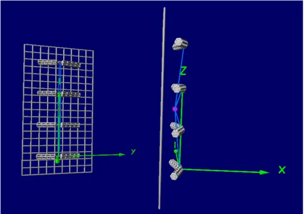
Back plane plays an important role in increasing directivity. Certain character-istics of the array are compared after the addition of back plane such as input impedance, return loss, gain and front-to-back ratio. The back plane affects the radiation patterns, gain, directivity and front-to-back ratio. Its size is already given and it is about 1000 mm x 500 mm. We made a grid using number of hori-zontal and vertical wires and the separation from the center of the antenna to the back plane is about λ/4, to get minimum number of side lobes. We model a wire
mesh of 9 horizontal and 18 vertical sections. Its size improves gain and front-to-back ratio. Although, increasing the size of front-to-back plane enhances the performance of antenna but it also increases the size of antenna that may be mounted on top of the tower. Figure 4.7 gives the 3D geometry of the array in the presence of finite back plane.
Figure 4.7: Dipole array with back Plane, front and side view
4nec2 provided consistent results about the characteristics of the array. How-ever, the center frequency is slightly shifted in the simulations. Table 4.2 gives summary of the characteristics of the antenna compared with Kathrein antenna at resonance frequency in both horizontal and vertical planes. The simulated results of the broadband dipole array for the VSWR, return loss, gain, SLL, front-to-back ratio and beamwidth well agree with that of Kathrein antenna. Return loss is even better than Kathrein antenna. The half power beamwidth is slightly smaller than Kathrein antenna which is reasonable because of getting higher gain.
Table 4.2: 4nec2 results compared with Kathrein antenna at resonance frequency
4nec2 Kathrein
Plane Horizontal Vertical Horizontal Vertical VSWR 1.082 1.082 1.1 1.1 Return Loss 28 dB 28 dB 26 dB 26 dB Gain 12.3 dB 12.3 dB 11dB 11 dB Side Lobe Level NA -11 dB NA NA Front-To-Back Ratio 18.9 dB 18.9 dB NA NA Beam Width 60o 24o 62o 28o
4.2.1
Far-field Patterns
The back plane affects the radiation pattern of the array. In case of infinite back plane there is no back lobe. However since we are using back plane with finite size there will be back lobes. but, its level will be smaller than the main lobe as shown in Table 4.2.
Both, horizontal and vertical patterns are plotted at f=640 MHz on Figure 4.8. Horizontal pattern is in xy-plane, while xz-plane contains vertical pattern. The distance between the back plane and the array is λ/4 in order to have less number of side lobes. If this distance becomes greater than λ/4, we may get some more side lobes apart from those coming due to array factor and number of elements.
Figure 4.9: Magnitude of |Zin| for dipole array
4.2.2
Input Impedance
The impedance variation with frequency is very important in the sense of band-width. If the variation is larger it can cause more reflections at the input. Fig-ure 4.9 gives the magnitude of the input impedance for the cases of with and without the backplane. The magnitude of impedance is dropped to some range of values at certain frequencies in comparison to array without the back plane.
It is varying around 80Ω -100Ω in the desired band. It is about 80Ω near center frequency, back plane reduced the impedance variation with frequency.
Figure 4.10: Phase of Zin for the dipole array
The phase variation in the required operational band also becomes smaller with the addition of the back plane. Figure 4.10 illustrates the phase variation of the input impedance. The phase was about −40o at center frequency before
adding the back plane. It become close to 0o around center frequency due to the inclusion of the back plane.
4.2.3
Return Loss
Return loss is improved as the input impedance variation with frequency becomes smaller in the desired band. The magnitude of the input impedance is varying
Figure 4.11: Reflection coefficient of dipole array
return loss above 10 dB. The bandwidth of the antenna after adding a back plane is much more improved. It was about 290 MHz before the back plane. With the back plane, bandwidth becomes about 560 MHz by looking at the reflection coefficient plots shown in Figure 4.11. Moreover, the return loss was low at the center frequency before. It even becomes above 25 dB near the center frequency with the back plane. The antenna array is matched very well in the desired band(470 - 860 MHz) of operation after the addition of the back plane.
4.2.4
Gain and Front-To-Back Ratio
The back plane also affects the gain and front-to-back ratio of the array. Fig-ures 4.12 and 4.13, respectively, show gain and front-to-back ratio of the array. The gain of the antenna increases with frequency and at the same time side lobe
will also increase. Antenna becomes more directive at higher frequencies with low front-to-back ratio.
Figure 4.12: Gain of the dipole array
Despite the fact that the gain of the antenna increases with frequency but front-to-back ratio also increases very slowly in case of array without the back plane. It can be due to non-symmetry of pattern because the dipoles are bent by 17o from the center and the patterns obtained from bent dipoles are not
totally symmetric. In this case the gain of the antenna is about 9 dB near center frequency while front to back ratio is about 0.7 dB. Gain of the antenna near mid of the band is about 12.5 dB, while front-to-back ratio is about 18.5 dB when the back plane is included. Here gain increases while front-to-back ratio decreases with frequency. It must be noted that when the frequency is sufficiently large in comparison to center frequency, the gain starts decreasing. It may be due to the current exciting the antenna passes through number of zeros, which distorts the
Chapter 5
Parasitic effect of Antenna
Towers
In this section, we will discuss the modeling of tower as a parasitic element. Its effect on the patterns, return loss, input impedance, gain, and front-to-back ratio will be discussed. There are many factors that must be taken into consideration while designing towers. For instance, environmental factors including wind and ice loading which affect tower life. Also, height, volume, structure type (rectan-gular or trian(rectan-gular), present and future loading must be carefully considered.
In this section, we are interested to see the parasitic effect of the tower on the characteristics of antenna.
5.1
Tower Structure in 4nec2
We used four equal face tower(rectangular tower) with each face about one meter and the total height of the tower is 30 meter. In 4nec2 using “4nec2 Editor New”, tower is designed in such a way that the height of tower is along z-axis and it is centered at the origin. Four legs(each 1 meter) are interconnected with multiple
horizontal ring girth. These four legs connected to ring girth are repeated 27 times using GM card. The tower is ready and antenna can be mounted on top of it. The structure of tower made in 4nec2 is shown in Figure 5.1.
Figure 5.1: Tower structure in 4nec2
The radius of the wires used for making tower are based on 4nec2 design rules. If the radius and number segments of the wires do not satisfy 4nec2 rules, then, we will run into segment check error or warnings. However, since the tower itself is not excited, one may ignore segment check error. While making tower, we used
a wire with a radius of 7 mm.
5.2
Antenna with Tower in 4nec2
To see the parasitic effect of the tower, antenna array designed in the previous section is mounted on top of the tower. Combing two separate programs (4nec2 codes) of the tower and antenna requires modification of tag numbers. Tag num-bers are modified so that it can give continuity of numnum-bers in one program. The antenna is mounted at a height of 28 meters. Figure 5.2 illustrates the mounted antenna array on top of the tower.
5.3
Effect of the Tower on Antenna
Character-istics
The configuration of tower with a panel antenna is simulated to see its effect on the antenna characteristics such impedance bandwidth, return loss, input impedance, gain and front-to-back ratio.
5.3.1
Input Impedance
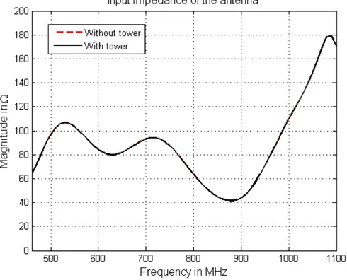
Parasitic effect of the tower on the input impedance of the antenna array is studied. Magnitude and phase of the input impedance after mounting antenna on top of a tower are illustrated by Figure 5.3 and 5.4 respectively. In the plot,
Figure 5.3: Effect of the tower on magnitude of Zin of the antenna
the two curves are overlapping each other, which means the difference between them is zero. Tower has no effect on the magnitude of input impedance of the
antenna due to back plane of the array separating tower and antenna array. Also, it has no effect on the phase of input impedance as can be seen from Figure 5.4.
Figure 5.4: Effect of the tower on phase of Zin of the antenna
5.3.2
Return Loss
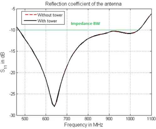
Input impedance of the array is not changing by the parasitic effect of the tower. It remained the same as it was before. The return loss at the input of array will also not change with the tower, since the input impedance is not changing. As a result, we will get the same bandwidth from return loss plot by looking at the frequency where return loss is equal or above 10 dB. The of return loss being higher than 10dB appears as 560MHz. Figure 5.5 shows the effect of the tower on the return loss of the antenna. It can be said that panel antenna is a suitable choice for broadcast applications as tower has almost no effect on its impedance and bandwidth.
Figure 5.5: Effect of the tower on reflection coefficient of the antenna
5.3.3
Gain and Front-To-Back Ratio
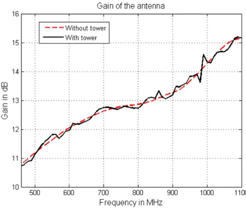
Figure 5.6 depicts the effect of the tower on the gain of the antenna. The gain of the antenna is marginally increased due to reflection of back lobe from the faces of tower at particular frequencies. Reflected back lobe may be added to the gain constructively or destructively, which fluctuates the gain of the antenna.
Figure 5.7 shows effect of the tower on the front-to-back ratio of the antenna. Parasitic effect of the tower on front-to-back ratio is significant at certain fre-quencies. The back lobes are not totally zero because of the diffraction from the edges and finite area of the back plane. It can also be due to the back plane made of wire grids containing vertical and horizontal sections. Back lobes get reflected from the tower, which minimize the level of back lobe at some angles. In turn it increases the front-to-back ratio of the antenna at some frequencies.
5.3.4
Far-field Patterns
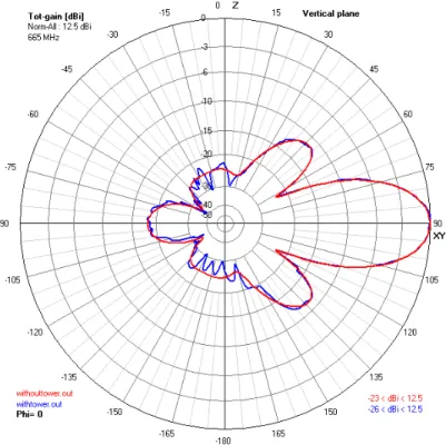
Tower effect on the vertical and horizontal patterns are depicted in figure 5.8 and 5.9 respectively.
Figure 5.8: Effect of the tower on the vertical pattern of antenna
In the previous section, we have seen that the front-to-back ratio was disturbed more than the gain of the antenna by the parasitic effect of tower. We can further see it here that the back lobe gets lowered by the tower which is responsible for the increase of front-to-back ratio. Side lobes are also affected slightly whereas main lobe remain intact.
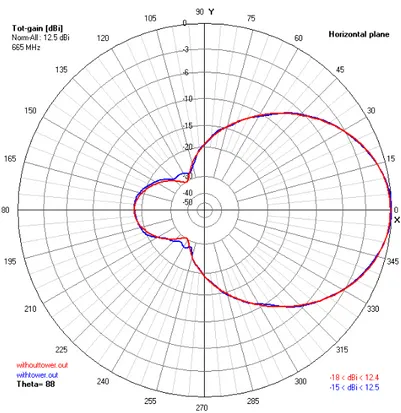
On the other hand, horizontal pattern is slightly affected by the tower in comparison to the vertical pattern of the antenna. Here the back lobe is increased marginally compared to the pattern of the antenna modeled without the tower. Overall effect of the tower on the horizontal pattern is minimum.
Figure 5.9: Effect of the tower on the horizontal pattern of antenna
5.4
The Nearby Tower Effect
A nearby tower also affects the radiation characteristics of the broadcasting an-tenna mounted on a tower. To see the effect of the nearby tower, we generate a copy of the tower and antenna designed in the previous section. The nearby tower is placed at a certain distance in the main beam direction of the broadcasting antenna. We have the following two cases to see the effect of a nearby tower.
1. Nearby tower without antenna 2. Nearby tower with antenna
Figures 5.10 and 5.11, show the structures of the towers for the two cases along with the vertical radiation pattern of the broadcasting antenna. In first case, there is no antenna on the nearby tower while in second case there is an antenna on the
Figure 5.10: Structure of the two towers, when there is no antenna on the nearby tower
Figure 5.11: Structure of the two towers, when there is an antenna on the nearby tower
nearby tower. The antenna on the nearby tower is not excited. The separation between the two towers is varied and characteristics of the broadcasting antenna such as far-field patterns, reflection coefficient, gain and front-to-back ratio are monitored continuously for the two cases.
5.4.1
Far-field Patterns
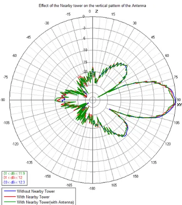
Figures figs. 5.12 to 5.15 and figs. 5.16 to 5.19 show vertical and horizontal radiation patterns respectively of the broadcasting antenna at different distances. In these figures, we compared the two cases of the nearby tower at f=640 MHz.
The nearby tower has some affect on the far-field radiation patterns of the broadcasting antenna for instance, when the separation between the two towers is 50m or 100m, the vertical and horizontal patterns of the broadcasting antenna are affected more by the nearby tower for the two cases. However, in the case when the nearby tower contains antenna, it affects the patterns of the broadcasting antenna more than the nearby tower without an antenna. The nearby tower introduced distortion in the radiation patterns of the antenna. On the other hand, when the separation between the two towers is at least 150m then, both cases of the nearby towers have smaller effect on the radiation patterns of the broadcasting antenna.
5.4.2
Input Impedance and Return Loss
Figures figs. 5.20 to 5.23 show input reflection coefficient at different distances. Input impedance and return loss of the broadcasting antenna are affected more by the nearby tower, when separation between the two towers is at most 9 meter. In case of the nearby tower without an antenna, the effect on the reflection coefficient of the broadcasting antenna is minimum in comparison to the nearby tower with an antenna. At d=5m, effect of the nearby tower (without antenna) on S11 is
Figure 5.12: Effect of the nearby tower on the vertical pattern at d=50m
Figure 5.16: Effect of the nearby tower on the horizontal pattern at d=50m
Figure 5.20: Effect of the nearby tower on S11 of the antenna when d=5m
Figure 5.24: Effect on the gain of the antenna in case of nearby tower without an antenna
than 10 dB due to the strong coupling between the broadcasting antenna and the antenna on the nearby tower at d=5m. As the separation between the two towers increases, the coupling between two antennas decreases.Thus, when the separation between the two towers becomes small, then nearby tower with antenna affects the input impedance and return loss of the broadcasting antenna.
On the other hand, when the separation between the two tower is at least 14m, then nearby tower effect on the input impedance and reflection coefficient in either cases is almost negligible. Ultimately, the impedance bandwidth of the antenna remains unchanged.
5.4.3
Gain and Front-to-Back Ratio
Figures 5.24 and 5.25 illustrate the effect of the nearby tower without and with antenna on the gain of the broadcasting antenna respectively. In case of the nearby tower without antenna, the gain of the broadcasting antenna is affected
Figure 5.25: Effect on the gain of the antenna in case of a tower with an antenna more by the nearby tower at d=27m. The gain is reduced in comparison to the broadcasting antenna without the nearby tower. The effect of the nearby tower on the gain of the broadcasting antenna is dependent on the frequency for instance, when the separation is 35m then, the gain is affected more in the higher band of the frequencies. As the separation between the two towers increases the effect of the nearby tower on the gain becomes minimum.
The gain of the broadcasting antenna is affected by the nearby tower with antenna and it depends on the frequency. It fluctuates with the frequency. The broadcasting antenna induced a small current on the antenna of the nearby tower, which radiate weak electromagnetic field. The weak EM field interferes construc-tively or destrucconstruc-tively with the EM field of the broadcasting antenna as a result the gain fluctuates with frequency. The effect of the nearby tower with antenna becomes minimum on the gain when the separation is at least 54 meter. Con-trasting nearby tower with and without antenna, we observed that nearby tower with antenna has more effect on the gain of the broadcasting antenna.
Figure 5.26: Effect on the F/B ratio of the antenna in case of a tower without an antenna
antenna respectively on the front-to-back ratio of the broadcasting antenna. The front-to-back ratio fluctuates with frequency in both of the cases and at some of the frequencies, the effect on the front-to-back ratio is high. In case of the nearby tower without an antenna, the effect on the front-to-back ratio is small when the towers are separated by a distance of at least 54 meter.
The nearby tower with an antenna affects the front-to-back ratio of the broad-casting antenna more in comparison to the nearby tower without an antenna. The effect of it on front-to-back ratio is minimum, if the separation is 63 meter or more.
These results are very important for a broadcast engineer. If in the main beam of the broadcasting antenna, there exist a unused tower and it is not at certain distance for the minimum distortion of the gain and front-to-back ratio, then it must be removed to get better radiation performance from the broadcasting antenna.
5.5
Effective Radiated Power
Effective radiated power(ERP) is an important parameter that is used in broad-casting. It can be calculated by adding maximum gain and transmitter output power in dB scale.
We will find ERP by putting antenna arrays on each face of the tower. For this purpose if we use wideband array designed earlier, then, we run into total number of segments exceeding the limits of NEC, So we will use antenna array made up of thin wires, which may not be wideband. To find the ERP from 4nec2 simulation results, one should look at the output text file generated by the program. The output file contains many information about the antenna, but we are interested in the radiated power, which can be found under the heading power budget. Figure 5.28 gives summary of power budget from the output file.
Figure 5.28: Power budget of the antenna
The gain of the antenna is 13.5 dB and radiated power is about 192.78 Watts. In dB scale the radiated power is about 22.84 dBW. The ERP is the sum of gain and radiated power in dB. It is 36.35 dBW in this case. ERP do not change whether to mount antenna array at each face or single face of the tower. Directiv-ity and radiated power changes with the addition of antenna array at each face of the tower, but ERP remains constant. With the addition of the antenna array at other faces of the tower, one can give coverage to wider area, but directivity will decrease and radiated power will increase. Table 5.1 gives gain, radiated power and ERP by mounting antenna array at one face or on multi faces.
Table 5.1: ERP with Different Configuration Antenna at Gain(dB) Prad(dBW) ERP(dBW)
one side 13.5 22.84 36.35 two side 10.5 25.826 36.33 three side 9.71 27.625 37.33 four side 8.46 28.9 37.36
When four set of antenna arrays are mounted at each face of the tower, we get almost omni directional like pattern with some gaps. ERP is an important factor for broadcast engineer, he/she can decide where to mount an antenna at the top of a tower for instance at single face or multi face and he can adjust the input power to get desired ERP. As an example when antenna is mounted at every face of tower, the horizontal pattern is given in Figure 5.29. In such a case, the gain
decreases and radiated power must increase to keep the same ERP.
4nec2 can be a useful tool for broadcast engineer, before installment of any new tower at any location, he/she can perform some simulations. He/She can do general survey of the location by identifying the nearby structures such as towers and the type of ground plane(e.g moderate, average, dry, sandy, coastal, fertile land etc.). In 4nec2, he can easily model ground planes , metal structures and its effect on the tower to be installed.
Chapter 6
Design of Stacked Suspended
Plate Antennas for Broadcasting
This section is about the design of the stacked suspended plate antenna(SSPA) with simulation and measured results. The antenna consist of ground plane, primary plate, secondary plate, vertical plate and feeding structure. Feeding structure capacitively feeds the primary plate, which in turn feeds the secondary plate in the same way. The height of primary and secondary plates from ground plane, position of feed point on ground plane and separation between primary and feeding plates are important parameters that must be tuned to get better performance from the SSPA.
6.1
Antenna Geometry
The antenna is designed at the center frequency fc=202 MHz(λc=1485 mm) of the
VHF frequency band in Turkey. The dimensions of the antenna are determined after in-depth parametric study in terms of return loss, gain, bandwidth and radiation patterns. The structure of the antenna, which includes top view, side view and front view are depicted in Figures 6.1 and 6.2. For the simulations,
Figure 6.1: Geometry of SSPA antenna
we used CST microwave studior. In CST microwave studior, the antenna is
configured to radiate along the x-axis so that vertical and horizontal patterns can be obtained with minimal effort. The dimensions of modified inverted L-probe feed are(hf = 0.07166λc, Wf = 0.1433λc, Lf = 0.1075λc). The vertical plate is at
0.493λc from the feed point denoted by VY.
The position of feed point on ground plane is also important [15] and it is not exactly in the center. The position of feed point(Xf, Yf, Zf) is (0,Lg/2,0.197λc).
It must be noted that modified inverted L-probe consist of triangular and rect-angular plates, where the trirect-angular plate connects the rectrect-angular plate after a gap of Le = 6mm(0.0043λc). Table 6.1 summaries rest of the dimensions of the
stacked suspended plate antenna .
The antenna is fabricated using 0.1 mm thick copper foil [15] and supported by foam with permitivity of 1.05. Primary plate is the main radiator, which is excited through electromagnetic coupling by inverted L-probe section of SSPA.
Figure 6.2: Geometry of SSPA antenna, front view
To get better results for return loss, gain and bandwidth, a secondary plate is introduced. Further matching and desired beam-width of the patterns are obtained through the insertion of vertical plate between primary plate and ground plane shown in Figure 6.2, where the small gaps Vx1 and Vx2 are equal to 1 mm
and 3 mm respectively.
Table 6.1: Dimensions of SSPA
Structure Type Length Width Height Ground Plane Lg = 0.896λc Wg = 0.753λc hg = 0
Primary Plate Lp = 0.394λc Wp = 0.394λc hp = 0.1125λc
Secondary Plate Ls = 0.337λc Ws= 0.337λc hs = 0.1899λc