A
bstrAct
The everchanging telecommunication industry is in severe need of a highly skilled workforce to shape and deploy future generation communi-cation systems. This article presents innovative telecommunication training that is designed to satisfy this need. The training focuses on hard-ware layers of the open systems interconnection model. It integrates theory, numerical modeling, and hardware implementation to ensure com-plete and long-lasting understanding. The key telecommunication concepts that are covered in the fundamental training phase are detailed along with best teaching practices. In addition, methods that enrich the learning experience, such as gam-ified microtasks and interactive use of daily tele-communication devices, are featured. The project development case studies that cultivate creative thinking and scientific interest are highlighted. Also, a well-established guideline to compose the teaching environment that emphasizes hands-on experience is provided. Therefore, the presented training can be exemplary to other institutions that share the same mission to educate the distin-guished engineers of the future.
I
ntroductIon
Telecommunication technologies have been evolving from smoke signals to deep space high-definition videoconferences at an accel-erating pace [1, 2]. Such a thriving technology requires a vast number of highly skilled engi-neers. Therefore, well-designed training is needed to satisfy the everchanging telecommunication industry’s thirst for resilient professionals. Distin-guished telecommunication engineers must have a solid understanding of the fundamental theory, an ability to translate this theoretical knowledge into numerical implementation, and the capabili-ty of implementing them in hardware. Also, they must be equipped with independent thinking and creative problem-solving skills to pioneer future telecommunication systems. Furthermore, these prodigious engineers have to express their ideas clearly and function effectively in a team. This article presents innovative telecommunications training that is designed to cultivate equipped telecommunication engineers by instilling the fol-lowing abilities:
• To identify, formulate, and solve telecom-munication systems’ problems by applying
principles of mathematics, digital signal pro-cessing (DSP), electromagnetic (EM) wave propagation, and communication theory • To apply these fundamental concepts to
design and test spectral/energy-efficient advanced telecommunication systems con-sidering a wide variety of system scenarios, channel conditions, and hardware limitations • To present designs and document outcomes
taking a diverse audience into account
The training emphasizes hands-on experience and focuses on hardware layers of the open sys-tems interconnection (OSI) model [3]. At least a senior-level standing in electrical engineering is required for the proposed training. Not only students but also industry professionals who are looking to expand their understanding of tele-communications are targeted. Although there are several courses considering either a particular technology [4–6] or a teaching method [7, 8], the proposed training covers various telecommuni-cation technologies and integrates many modern teaching methods such as gamified microtasks and novel doubly dispersive channel emulators. The foundations of the suggested training were laid in [9], and the training is rebuilt by including emerging concepts, contemporary teaching meth-ods, and futuristic projects over the last decade.
M
odern
t
eAchIng
M
ethodologIes
Comprehending certain subjects such as tele-communications is very challenging due to their highly abstract nature. Classical theoretical train-ing prevents observtrain-ing the immediate relation-ship between cause and effect. Also, theoretical knowledge without practice is destined to perish. A complete understanding can be achieved by an interactive learning experience [10, 11] as shown in Fig. 1. The proposed telecommunication engi-neering training is structured to modernize such a well-proven methodology.A solid design builds on a good understand-ing of theoretical concepts. However, telecom-munication systems exhibit numerous nonlinear behaviors that make them difficult to model with closed-form expressions. Therefore, numerical models are widely used to assist in the evalua-tion and visualizaevalua-tion of such complex systems. Trainees can manipulate the system and subsys-tem parameters independently and grasp their individual effects using various numerical tools. These skills are especially critical in their
profes-Ali Fatih Demir, Berker Peköz, Selçuk Köse, and Hüseyin Arslan
TELECOMMUNICATION AND NETWORK ENGINEERING EDUCATION
The ever changing tele-communication industry
is in severe need of a highly skilled workforce to shape and deploy future generation communica-tion systems. The authors
present innovative tele-communication training that is designed to satisfy this need. The training focuses on hardware
lay-ers of the open systems interconnection model. It integrates theory, numerical modeling, and hardware implementation to ensure complete and long-lasting understanding.
Ali Fatih Demir, Berker Peköz, and Hüseyin Arslan are with the University of Sourth Florida: Hüseyin Arslan is also with Istanbul Medipol University;
Selçuk Köse is with the University of Rochester. 10.1109/MCOM.001.1900245Digital Object Identifier:
Innovative Telecommunications Training
through Flexible Radio Platforms
sional career since troubleshooting problems with such tools is easier than fixing them in the hard-ware prototyping stage. Nonetheless, the validity of the aforementioned models is limited by the assumptions. Therefore, theoretically and numer-ically verified designs must also be implement-ed in hardware and testimplement-ed under various channel conditions and realistic scenarios. The hardware implementation can be achieved practically using fl exible radio platforms. Also, it should be pointed out that the numerical and hardware implemen-tations provide a convenient way for trainees to design telecommunication systems by themselves and assist reinforced learning.
The fundamental concepts of hardware layers are modularized and taught separately to examine each subsystem rigorously. In light of the discus-sions above, ideal training should integrate theory, numerical modeling, and hardware implementa-tion to train future telecommunicaimplementa-tion engineers well. Therefore, each training module starts with a theoretical discussion, followed by numerical anal-ysis, and is completed with hardware implementa-tion in the laboratory. The laboratory experiments feature telecommunication devices that are used daily such as smartphones and FM radio receivers to interest trainees. Furthermore, gamifi ed micro-tasks motivate them and establish confi dence in this challenging fi eld. The details of each module are given in the following section. At the end of each module, trainees are expected to deliver a technical report summarizing their key observa-tions. These reports allow receiving immediate feedback regarding trainees’ progress and help them keep on track throughout the fundamental training phase. Upon successful completion of this phase, trainees are examined, and they pro-ceed to the independent project development phase to demonstrate their vast proficiency on the topic.
d
esIgn
oF
t
elecoMMunIcAtIon
e
ngIneerIng
t
rAInIng
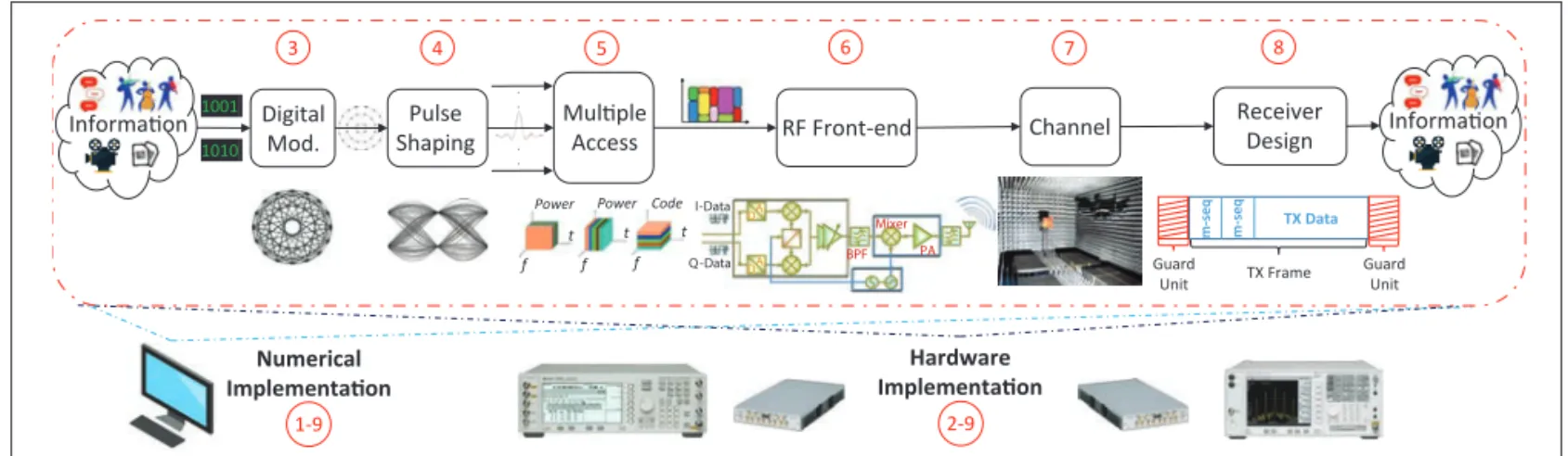
The proposed training teaches telecommunica-tions with an emphasis on physical, data link, and network layers. The training content presents the journey of bits through telecommunication sys-tems, as depicted in Fig. 2. An instructor must compose the teaching environment carefully to deliver this content eff ectively. Once the teaching environment is established, the fundamental train-ing and independent project development phases
can be conducted. The total training duration depends on the audience. For example, the train-ing is offered to students in 15 weeks, whereas the training is delivered to industry professionals to various extents. A good rule of thumb would be to allocate 2/3 of the fundamental training period for the independent project development phase.
t
hec
oMPosItIonoFAt
elecoMMunIcAtIont
eAchInge
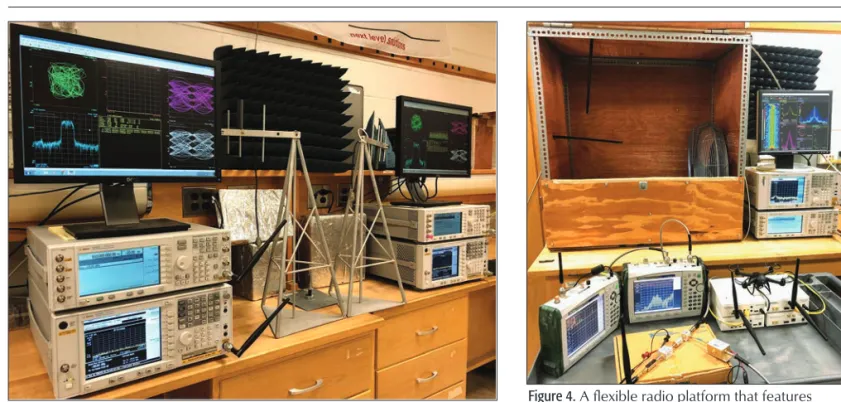
nvIronMentThe theoretical content and numerical modeling can be taught either in a conventional computer laboratory or remotely. On the other hand, the hardware implementation requires a fl exible radio platform that consists of software-defined radio (SDR)-capable transmitter and receivers along with the modular RF front-end and confi gurable chan-nel emulators. A basic SDR testbed includes a vec-tor signal generavec-tor (VSG), a vecvec-tor signal analyzer (VSA), and a computer that runs telecommunica-tion system design and analysis tools as well as cables/antennas, as shown in Fig. 3. A VSG can generate signals using various digital modulation techniques and baseband pulse shapes. Also, it can multiplex them in various domains such as time, frequency, and code to obtain standard and custom waveforms. These waveforms can be gen-erated either internally using the VSG in stand-alone operation or externally using the computer, and are conveyed to VSAs. A VSA has the ability to demodulate the standard and custom signals in a standalone mode similar to a VSG. Also, it can convey the in-phase and quadrature (IQ) sam-ples of the received signal to a computer for pro-cessing. The interaction between a computer and VSGs/VSAs is an excellent mechanism for teach-ing, studyteach-ing, and analyzing current and upcoming telecommunication systems.
Figure 1. The cone of learning adapted from [10]. Read Hear See Theoretical Evaluation Numerical Evaluation & Implementation Hardware Implementation Discuss & Document Observations
Design & Implement Project Present & Document Project Design & Conduct Training
Fundamental Training Phase Independent Project Phase Mastery
Figure 2.Functional model of the fundamental training.
1001 1010 . . . . 3 4 5 6 7 8 Guard Unit m -seq TX Data TX Frame Guard Unit m -s eq Power Power f t Code f t f t Hardware Implementation 2-9 Numerical Implementation 1-9 Digital Mod. Pulse
Shaping Multiple Access RF Front-end Channel
Receiver Design Information Information Mixer PA BPF I-Data Q-Data A D DA
The system design, scenarios, and channel con-ditions can be enriched further by extending the testbed with mobile transceivers, a modular RF front-end, and channel emulation tools as present-ed in Fig. 4. IQ modems, digital-to-analog convert-ers (DACs), analog-to-digital convertconvert-ers (ADCs), mixers, voltage-controlled oscillators (VCOs), power amplifiers (PAs), bandpass filters (BPFs), cables, and antennas are some of the critical RF front-end components of telecommunication sys-tems. Testing and measuring a telecommunication system using a modular RF front-end provides the ability to analyze the function and effect of each component separately. In addition, mobile trans-ceivers allow emulating various scenarios such as cellular handoff and positioning. For high accu-racy requirements, handheld VSGs and VSAs are preferable, whereas an abundance of low-cost SDR hardware is more convenient for experi-enced trainees to emulate applications involving networking and interference management. Fur-thermore, diverse channel conditions can be mim-icked via reverberation and anechoic chambers, unmanned aerial vehicles (UAVs), and metal fans [12]. The frequency selectivity of the channel is controlled through the use of chambers, whereas time selectivity is managed using multispeed fans.
F
undAMentAlt
rAInIngP
hAseBasic telecommunication concepts can be taught in eight modules, as numbered in Fig. 2. Also, the final module adapts trainees to contemporary telecommunication systems. A detailed descrip-tion is provided at the training website,1 and the key components of these modules are summa-rized as follows:
1. Introduction to the Basic
Telecommuni-cation Concepts: In this module, the
theoreti-cal aspects of the concepts that will be covered throughout the training are introduced. Also, a transceiver is modeled numerically to present the complete picture of a telecommunication system. First, text messages for each testbed are encod-ed to bits, modulatencod-ed, pulse-shapencod-ed, and
multi-plexed into different bands in the presence of additive white Gaussian noise by the instructor. The waveforms are supplied to trainees with com-binations of various RF impairment (i.e., frequency offset, phase noise, and PA nonlinearities) levels and signal-to-noise ratios (SNRs). Trainees are required to down-convert the signals and devel-op baseband receiver algorithms to complete the gamified microtask of this module, which is detecting individualized transmitted messages. Also, trainees assess the performance through the observation of bit error rate (BER) and sever-al diagrams such as constellation, IQ polar, and eye. The benefit of this module is twofold. First, trainees get familiar with the identification of tele-communication systems’ problems. Second, train-ees become acquainted with utilizing numerical tools to design and analyze telecommunication systems.
2. Introduction to the Basic SDR Testbed: The
primary objective of this module is to familiarize trainees with a basic SDR testbed. Trainees gener-ate standard single-carrier and multicarrier wave-forms at the VSGs and assess their performance using the built-in functions of the VSAs along with the corresponding computer software. The con-cepts that are theoretically and numerically covered in the first module are implemented in the hard-ware. The instructor allocates a different portion of the industrial, scientific, and medical (ISM) band to each testbed, and trainees practice transceiving cus-tom telecommunication signals. Not only the signals that are generated by VSGs but also over-the-air sig-nals such as FM, WiFi, and PCS are analyzed in this module. Observing the FM radio spectrum interests trainees and relates the taught concepts to daily life. Also, the burst transmission structure in ISM and PCS bands on WiFi and cellular calls is demon-strated. In the last part of the module, the received signal at a VSA is downloaded to a computer, and spectro-temporal characteristics are analyzed using numerical tools. This part is especially important to illustrate the interconnection between the compo-nents of a basic SDR testbed.
Figure 3. Basic SDR testbeds each consisting of a vector signal generator (VSG), a vector signal analyzer (VSA), a computer, and cables/antennas.
Figure 4. A flexible radio platform that features mobile SDR equipment, a modular RF front-end, and configurable channel emulators.
1 http://wcsp.eng.usf.edu/
3. Digital Modulation: Trainees commence the telecommunication system design by map-ping bits to symbols after the overview in the first two modules. The theory part of the module teaches the purpose of digital modulation and its limiting factors such as SNR and peak-to-average power ratio (PAPR). In the numerical and hard-ware implementation parts, various modulation schemes are demonstrated using built-in functions and characterized in terms of power efficiency, spectral efficiency, and ease of implementation. The analyses start with the throughput comparison of binary phase shift keying (BPSK) and higher-or-der quadrature amplitude modulation (QAM) and PSK modulation schemes as a function of SNR to demonstrate the trade-off between spectral and energy efficiency. This trade-off is made clear through the observation of error vector magni-tude (EVM), IQ polar diagram, eye diagram, and power CCDF curve. After initial characterization, alternative modulation schemes such as p/2-BPSK, p/4-differential quadrature PSK (DQPSK), offset QPSK (OQPSK), and minimum shift keying (MSK) that enhance PAPR to overcome hardware limita-tions at the expense of implementation complexity are demonstrated and examined. After trainees comprehend the distinguishing characteristics of various digital modulation schemes, the instructor transmits a signal, and trainees attempt to figure out the digital modulation scheme blindly. Trainees understand the motivation behind the existence of various digital modulation schemes and link adap-tation to channel conditions in this module.
4. Baseband Pulse Shaping: The objective of
this module is to study the impact of baseband pulse shaping filters, which map digitally modulat-ed symbols into waveforms, on telecommunica-tion system performance. The discussions take off with orthogonal raised cosine (RC) filters. Train-ees alter the roll-off parameter that controls the spectro-temporal characteristics, and they observe changes in the spectrum, time envelope, power complementary cumulative distribution function (CCDF) curve, IQ polar diagram, and eye diagram. Furthermore, the performance of the RC pulse shaping filter at the transmitter side is compared to using a root raised cosine (RRC) pulse shaping filter at both the transmitter and receiver, and the superiority of matched filtering is demonstrated. Also, an RRC pulse-shaped signal is transmitted without matched filtering at the receiver, and the presence of inter-symbol interference is pointed out. Once trainees are accustomed to the non-orthogonality in the filter design, the discussion continues with Gaussian pulse shaping filters that are preferred due to their spectral confinement. The similarity between the bandwidth-time (BT) product of Gaussian pulse shaping filters and the roll-off factor of RC pulse shaping filters are point-ed out. GSM signals with different BT products are generated, and their performances are eval-uated as similar to RC pulse-shaped signals. After understanding the spectro-temporal characteristics of baseband pulse shaping filters, the instructor transmits signals, and trainees predict the filter parameters. The fundamentals of spectrum- and energy-efficient design are taught in this mod-ule, and robust filter design against RF front-end impairments and multiple access wireless channel are further elaborated in the following modules.
5. Multiple Access: The purpose of this
mod-ule is to acquaint trainees with resource allocation among multiple users and to manage the resulting interference. Previously, the testbeds share the channel in a frequency-division multiple access (FDMA) manner. In this module, they get familiar-ized with other multiple access schemes such as time-division multiple access (TDMA) and code-di-vision multiple access (CDMA). Initially, GSM sig-nals with varying relative burst powers for each slot are broadcast by the instructor. Each slot is assigned to a certain testbed along with associ-ated relative burst power. Trainees observe the TDMA frame structure and locate their slot. In the following stage, the instructor transmits various DSSS-CDMA signals by assigning different codes to each testbed. As the number of active codes increases, trainees observe the power CCDF curve and conclude that an increased number of random variables degrades PAPR characteristics. Also, a joint time-frequency analysis is performed on Bluetooth signals from two smartphones using the spectrogram. The smartphones’ distances to a VSA are utilized to identify the hopping structure of each frequency hopping spread spectrum code.
Upon introducing conventional resource allo-cation techniques, multiple access interference is explained. Adjacent channel interference (ACI) is demonstrated by transmitting equipower RRC pulse-shaped signals in adjacent bands simultane-ously without a guard band in between. Although the testbeds can demodulate their signals with slight performance degradation, they cannot demodulate each others’ signals properly due to the near/far effect. In this step, trainees utilize their knowledge from the previous module and adjust the RRC roll-off factor to mitigate ACI. In the next stage, testbeds generate single-carrier signals at the same frequency and emulate a cochannel interfer-ence scenario. They observed that their commu-nication performance significantly degrades since there is insufficient spatial separation between the testbeds. Afterward, one of the testbeds switches to the DSSS scheme, and it is demonstrated that spread spectrum systems are more robust against narrowband interference. This module integrates previously learned concepts and improves multidi-mensional signal analysis skills.
6. RF Front-End: Teaching the functionalities
and characteristics of critical RF front-end com-ponents is the core objective of this experiment. In the first stage of this module, the instructor informs trainees on IQ modems and familiarizes them with various impairments using the inter-nal IQ modulator on VSGs. IQ gain imbalance, quadrature offset, and DC offset are intentionally introduced, and their effect on IQ polar diagram, eye diagram, and EVM are exhibited. Following this stage, quantization effects are demonstrated by connecting an external DAC with various res-olutions to VSGs and altering the dynamic range of VSAs. Trainees observe the results of quanti-zation errors such as spectral regrowth, increase in EVM, and interpolation issues in eye and IQ polar diagrams. Afterward, the analog signal is conveyed to an upconverter unit that consists of a mixer and a VCO to shift the baseband signal to IF or RF. Trainees compare the stability of low-end standalone VCOs’ output with that of VSGs. The reference signals generated by both VCOs After trainees
compre-hend the distinguishing characteristics of various
digital modulation schemes, the instructor
transmits a signal, and trainees attempt to fig-ure out the digital
mod-ulation scheme blindly. Trainees understand the motivation behind the existence of various dig-ital modulation schemes
and link adaptation to channel conditions in
are passed through mixers for up-conversion. It is demonstrated that low-end standalone VCOs can-not output stable tones and produce phase noise.
Trainees analyze the effect of nonlinear behav-ior of mixers and PAs. First, they observe the spec-trum while operating the PA in the linear region. Hence, the harmonics generated only by the mixer are presented. Afterward, the transmitted power is gradually increased, and power CCDF curve, EVM, IQ polar diagram, and spectrum are observed. It is demonstrated that increasing the transmit power beyond the hardware limitations does not increase SNR. BPFs are provided to sup-press harmonics caused by both components. Furthermore, PAPR is reduced by using digital modulation techniques that omit zero crossings and utilizing RRC pulse shapes with a higher roll-off factor. Thus, trainees understand both the inconvenience of coping with the disadvantag-es of thdisadvantag-ese devicdisadvantag-es and techniqudisadvantag-es. Also, this module provides them an opportunity to build a complete RF front-end by connecting all the aforementioned components.
7. Propagation Channel: The purpose of this
module is to present fundamental EM wave prop-agation concepts. The channel imposes various effects on EM waves such as distance and fre-quency-dependent path loss, large-scale fading (i.e., shadowing), and small-scale fading (i.e., delay spread and Doppler spread). In the first stage, the distance and frequency-dependent charac-teristics of the path loss are depicted by measur-ing the signal with different antenna separations at different frequencies. Trainees sweep the FM band and record the received power levels of various stations. They obtain the transmit power, antenna height, and distance information online. Afterward, a simple statistical path loss model is derived considering the measurements from the stations with the same parameters. Also, shadow-ing is demonstrated by pointshadow-ing out the variation around the path loss.
Small-scale fading can originate from two phe-nomena: delay spread and Doppler spread. In the second stage, a reverberation chamber is used to control the delay spread amount in an indoor environment. Trainees alter the transmission band-width, and they observe a frequency-selective channel when the signal bandwidth exceeds the coherence bandwidth of the channel. It is chal-lenging to demonstrate mobility in an indoor environment. Either the transceiver or the environ-ment must be mobilized. A multispeed metal fan is utilized to create the variation in time. Trainees place a metal fan in between two antennas and operate it at different speeds while monitoring the spectrogram. Furthermore, a doubly-dispersive channel is emulated by moving the fan inside the reverberation chamber [12, 13]. Finally, trainees apply the concepts that are discussed in the pre-vious modules to design telecommunication sys-tems robust against channel effects. For example, the symbol rate is decreased to elevate immunity to delay spread, whereas it is increased to boost resistance to Doppler spread. Furthermore, the RRC roll-off factor is raised to improve the perfor-mance in both spreads with a penalty of degrad-ed spectral localization.
8. Receiver Design: The objective of this
module is designing a complete digital baseband
receiver. The instructor transmits a BPSK mod-ulated TDMA frame. The frame consists of indi-vidualized messages following different repeated m-sequences for each testbed. Trainees capture the signal and record it for offline processing. They start with the coarse time synchronization step to pinpoint the position of their desired mes-sage. Since two m-sequences are appended back to back, their autocorrelation gives a rough esti-mate of the allocated slot start. Upon the coarse time synchronization step, the frequency offset amount is estimated using the constant delay between the consecutive m-sequences. The esti-mated frequency offset is compensated for the frequency synchronization. Then fine time syn-chronization is performed by crosscorrelating the local m-sequence copy with the frequency off-set compensated signal. Trainees downsample the signal at the best sampling locations using the fine time synchronization information. Afterward, channel estimation must be carried out to com-pensate for the channel effect. The m-sequence of the received signal is compared to the local m-se-quence copy in order to estimate the wireless channel. The phase and amplitude of the received signal are corrected upon estimation. In the final stage, digital demodulation is performed, and esti-mated bits are mapped to characters to reveal the transmitted information. Trainees are thrilled to be able to demodulate a physical signal similar to their daily devices. This module finalizes the mod-ules that are pointed out in the functional diagram in Fig. 2 and demonstrates a complete picture of a basic single-carrier communication system.
9. OFDM: The main features of orthogonal
frequency-division multiplexing (OFDM) modula-tion are studied in the last training module. The instructor supplies trainees with a cyclic prefix (CP)-OFDM transmission script along with the VSG and VSA connection libraries. In the first stage, trainees are expected to develop their OFDM baseband receiver algorithms similar to the previous module. Since there is no m-se-quence in the frame, CP is used for time and frequency synchronization. Trainees repeat the hardware implementation steps of the RF front-end and propagation channel modules for multi-carrier communication after the receiver design. Fast Fourier transform (FFT) size, number of active subcarriers, CP length, and modulation order are altered in each step, and their effect on the tele-communication system performance is analyzed through power CCDF curve, constellation, and spectrum. Also, they compare the impairments for single-carrier and multicarrier communication schemes and point out the main differences. This module combines all the concepts that are cov-ered in this training within the perspective of an advanced modulation scheme that is used in cur-rent cellular and WiFi systems.
I
ndePendentP
rojectd
eveloPMentP
hAseTrainees become ready to pursue independent projects upon completion of the fundamental training phase. Although novelty is not enforced, it is highly encouraged. Considering the last 50+ projects that have been completed under the authors’ supervision, the feasible and educational projects are categorically summarized to inspire prospective trainees as follows:
Trainees sweep the FM band and record the received power levels of various stations. They
obtain the transmit power, antenna height,
and distance informa-tion online. Afterward, a simple statistical path loss model is derived considering the
mea-surements from the stations with the same parameters. Also, shad-owing is demonstrated
by pointing out the variation around the
Software-Defined Radio: The expertise acquired with the higher-end SDR platforms in the fundamental training phase equips trainees with the ability to build low-cost SDRs. These projects are especially suitable for embedded sys-tem developers seeking to implement Internet of Things transceivers. The budget-limited SDR hardware comes at the price of excessive RF front-end impairments. Trainees must also devel-op advanced baseband algorithms to mitigate IQ impairments, PA nonlinearities, and low-resolution DAC/ADC quantization issues.
Wireless Channel: The fundamental training
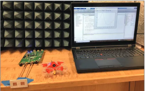
phase provides the ability to comprehend basic features of conventional cellular and WiFi chan-nels. Trainees with strong propagation engineer-ing backgrounds may characterize and model different environments such as the promising in-body channel, demonstrated in [14, Fig. 3]. Furthermore, advanced channel features can be extracted to determine line-of-sight/non-line-of-sight conditions or to design an object identifier via machine learning. Location services driven by channel properties are also compelling projects. Triangular positioning, channel-based authenti-cation, distance, and angle-of-arrival estimation techniques are exemplary candidates. Figure 5 illustrates an angle-of-arrival estimator for UAVs using a multiple-input multiple-output (MIMO)-ca-pable low-cost SDR. Moreover, the novel dou-bly-dispersive channel emulators [12, 13] used in the fundamental training phase were originally designed and implemented as trainee projects.
Wireless Channel Counteractions: After
obtaining a good understanding of channel char-acteristics, trainees can exploit them to improve telecommunication systems further. For example, MIMO systems are designed to take advantage of spatial diversity. Trainees with antenna and RF circuit design experience prefer MIMO front-end design and manufacturing, whereas trainees with solid communication theory backgrounds favor MIMO power allocation, channel estima-tion, and compensation projects. Furthermore, the mmWave channel, which will be deployed in 5G, can be studied as well. For instance, a train-ee dealt with the mmW blockage issue using an
adaptive antenna beam-width implementation as presented in [15, Fig. 2].
Signal Intelligence: Trainees with DSP and
communication theory backgrounds may utilize their extensive knowledge on multidimensional signal analysis and communication channel to pur-sue signal intelligence applications. These appli-cations include non-data-aided blind receivers, which estimate various parameters such as sym-bol rate, modulation type, and pulse shaping filter parameters in the presence of RF front-end and channel impairments. Furthermore, trainees can conceal the transmitted signal to prevent eaves-dropping using various single- and multi-antenna physical layer security techniques such as artificial noise transmission. Also, trainees may utilize chan-nel-based authentication methods to identify the legitimate transmitter as well.
Multiple Access and Interference
Manage-ment: The fundamental training phase mostly
cov-ers the centralized and orthogonal multiple access schemes. Alternative schemes such as cognitive radio (CR) and nonorthogonal multiple access (NOMA) attract trainees with data link layer inter-est and cultivate numerous projects. For exam-ple, the spectrum is utilized opportunistically in CR, and trainees avoid interfering with the prima-ry user. Furthermore, noncontiguous frequency resources can be aggregated in these projects. NOMA is another spectrally efficient resource utili-zation scheme and can be realized with multi-user detection, blind source separation, and interfer-ence cancellation algorithms. Moreover, trainees may manage self-interference and develop full duplex communication schemes to improve the capacity of telecommunication systems.
Standards: Trainees can improve their
exper-tise in telecommunication systems by partially implementing hardware layers of various standards such as 3G/4G/5G cellular, IEEE 802.11, Blue-tooth, and stereo FM. In addition, those inter-ested in the network layer may realize vertical handoff mechanisms to switch between different standards in a heterogeneous network scenario. Mobile SDR equipment is essential in these proj-ects. Moreover, trainees can assess new technol-ogies for future standards. For example, various waveforms might be implemented to evaluate their performance in realistic scenarios consider-ing diverse channel conditions, multiple access interference, and RF front-end impairments.
t
rAInee
I
MProveMent
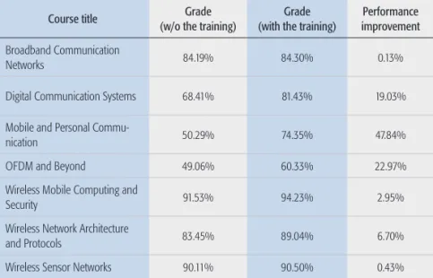
The fundamental training phase, which integrates theory, numerical modeling, and hardware imple-mentation, leads to competent telecommunica-tion engineers with a solid educatelecommunica-tion. Trainees who have completed the training are distinguished in their further telecommunication education and career. Their academic success was tracked, and their superiority to those who had not completed this training is revealed in both [9, Table V] and Table 1. Students’ final scores in telecommuni-cations-related courses from 2016 to 2019 are analyzed. Seventy students who have taken this training succeed better in the listed courses than 330 students who have not, as presented in Table 1. Also, [9, Table IV] points out that they feel more confident with telecommunication system design and analysis after the training.
Figure 5. A sample project: Angle-of-arrival estimator for UAVs using a MIMO-capable low-cost SDR.
The independent project development phase requires trainees to acquire and apply new knowl-edge as needed without well-defined instruc-tions and sharpens their analysis and synthesis skills. Also, it promotes teamwork and generates synergistic engineers. Trainees improve their presentation skills by demonstrating their proj-ects effectively to a wide ranging audience that includes undergraduate students, graduate stu-dents, faculty, and industry professionals. Discus-sions that take place during presentations and feedback received afterward are reportedly ben-eficial for professional interviews. The documen-tation of projects benefits technical writing skills. Furthermore, notable projects are encouraged for publication, and scientific interest among trainees is cultivated.
Finally, the instructors who are assisting train-ees throughout their telecommunication educa-tion journey also benefit from tutoring, which completes their mastery, as pointed out in Fig. 1.
c
onclusIons
Industry and academia require well-trained tele-communication engineers. The proposed train-ing is a well-established guideline to educate outstanding engineers and to build a bridge between these two institutions by integrating theoretical proficiency, numerical modeling skills, and hands-on experience. The provided array of skills as well as professional qualities help train-ees to succeed in their professional journeys and to design future generation telecommunication systems. Other institutions that are willing to set up similar training can profit from the expe-riences shared in this article. In particular, the improvement of trainees confirms the effective-ness and makes the proposed training a candi-date for flagship training in telecommunication education.
r
eFerences[1] S. Parkvall et al., “NR: The New 5G Radio Access Technolo-gy,” IEEE Commun. Standards Mag., vol. 1, no. 4, Dec. 2017, pp. 24–30.
[2] D. Consonni and M. T. M. Silva, “Signals in Communication Engineering History,” IEEE Trans. Educ., vol. 53, no. 4, Nov. 2010, pp. 621–30.
[3] ISO/IEC 8348:2002, “Information Technology — Open Sys-tems Interconnection — Network Service Definition,” Rev. 3, Nov. 2002.
[4] W. T. Padgett, B. A. Black, and B. A. Ferguson, “Low-Fre-quency Wireless Communications System-Infrared Laborato-ry Experiments,” IEEE Trans. Educ., vol. 49, no. 1, Feb. 2006, pp. 49–57.
[5] F. A. Cassara, “Wireless Communications Laboratory,” IEEE
Trans. Educ., vol. 49, no. 1, Feb 2006, pp. 132–40.
[6] Y. Linn, “An Ultra Low Cost Wireless Communications Lab-oratory for Education and Research,” IEEE Trans. Educ., vol. 55, no. 2, May 2012, pp. 169–79.
[7] H. Aliakbarian et al., “Implementation of a Project-Based Telecommunications Engineering Design Course,” IEEE
Trans. Educ., vol. 57, no. 1, Feb 2014, pp. 25–33.
[8] S. M. Berber and K. W. Sowerby, “Visual Presentation of Abstract Theoretical Concepts Using Animations in Com-munication Systems Courses,” Computer Applications in
Engineering Education, vol. 26, no. 1, 2018, pp. 49–61.
[9] S. Güzelgöz and H. Arslan, “A Wireless Communications Systems Laboratory Course,” IEEE Trans. Educ., vol. 53, no. 4, Nov. 2010, pp. 532–41.
[10] E. Dale, Audio-Visual Methods in Teaching, 3rd ed., Holt, Rinehart & Winston, 1969.
[11] N. Hoic-Bozic, V. Mornar, and I. Boticki, “A Blended Learn-ing Approach to Course Design and Implementation,” IEEE
Trans. Educ., vol. 52, no. 1, Feb. 2009, pp. 19–30.
[12] S. Güzelgöz, S. Yarkan, and H. Arslan, “Investigation of Time Selectivity of Wireless Channels Through the Use of RVC,” Measurement, vol. 43, no. 10, 2010, pp. 1532–41. [13] A. B. Kihero, M. Karabacak, and H. Arslan, “Emulation
Techniques for Small Scale Fading Aspects by Using Rever-beration Chamber,” IEEE Trans. Antennas Propag., vol. 67, no. 2, Feb. 2019, pp. 1246–58.
[14] A. F. Demir et al., “Anatomical Region-Specific in VIVO Wireless Communication Channel Characterization,” IEEE J.
Biomed. Health Info., vol. 21, no. 5, Sept. 2017, pp. 1254–62.
[15] S. Dogan, M. Karabacak, and H. Arslan, “Optimization of Antenna Beamwidth Under Blockage Impact in Millime-ter-Wave Bands,” Proc. 2018 IEEE 29th Annual Int’l. Symp.
Personal, Indoor and Mobile Radio Commun., Bologna, Italy,
Sept. 2018, pp. 1–5.
b
IogrAPhIesAli FAtih Demir [S’08] ([email protected]) received his B.S. degree in electrical engineering from Yıldız Technical University, Istanbul, Turkey, in 2011 and his M.S. degrees in electrical engi-neering and applied statistics from Syracuse University, New York, in 2013. He is currently pursuing a Ph.D. degree in the Depart-ment of Electrical Engineering, University of South Florida. Berker Peköz [S’15] received his B.S. degree in electrical and elec-tronics engineering from Middle East Technical University, Ankara, Turkey in 2015, and his M.S.E.E. from the University of South Flori-da in 2017. He is currently pursuing a Ph.D. degree in the Depart-ment of Electrical Engineering, University of South Florida. Selçuk köSe [S’10, M’12] received his B.S. degree in electrical and electronics engineering from Bilkent University, Ankara, Tur-key, in 2006, and his M.S. and Ph.D. degrees in electrical engi-neering from the University of Rochester in 2008 and 2012, respectively. He was an assistant professor of electrical engineer-ing at the University of South Florida. He is currently an associate professor of electrical engineering at the University of Rochester. hüSeyin ArSlAn [S’95, M’98, SM’04, F’16] received his B.S. degree in electrical and electronics engineering from Mid-dle East Technical University in 1992, and his M.S. and Ph.D. degrees in electrical engineering from Southern Methodist Uni-versity, Dallas, Texas, in 1994 and 1998, respectively. He is a professor of electrical engineering at the University of South Florida and the Dean of the School of Engineering and Natural Sciences at Istanbul Medipol University, Turkey.
Table 1. Academic success comparison.
Course title (w/o the training)Grade (with the training)Grade improvementPerformance
Broadband Communication
Networks 84.19% 84.30% 0.13%
Digital Communication Systems 68.41% 81.43% 19.03%
Mobile and Personal
Commu-nication 50.29% 74.35% 47.84%
OFDM and Beyond 49.06% 60.33% 22.97%
Wireless Mobile Computing and
Security 91.53% 94.23% 2.95%
Wireless Network Architecture
and Protocols 83.45% 89.04% 6.70%
Wireless Sensor Networks 90.11% 90.50% 0.43%
* The reader is referred to the website below for a detailed description of the courses listed: https://www.usf.edu/engineering/ee/