Huseyin Bulgurcu
Department of Air Conditioning and Refrigeration, Balikesir Vocational School of Higher Education, Balikesir University, 10023 Balikesir, Turkey
_______________________________________________________________________________________
Abstract
Process control laboratories in most colleges and universities include a single process trainer for control exercises in temperature, level, flow and pressure. Single trainers are present because of the size and cost of the systems; however, the use of single systems makes it difficult to use small laboratory teams without reducing the enrolment limit placed on the laboratory section. Ideally, the process laboratory should have multiple trainers in at least two of the four primary process variables to learn the basics of process control. Then the students could move to the larger more robust systems to study control of a large industrial process.
In this paper a multi control trainer has been developed in order to enable basic controls actions such as flow, level, pressure and temperature control. Process control apparatus of this multi control trainer can independently use on-off, float, P, PI, PD and PID control actions. On this device a water tank, a centrifugal pump, a global valve and driver, a tribune type fluid censor, a rotate-meter type flow meter, two pressure transducer, a SSR relay, an electrical heater an pressure tank, a heat exchanger and NC200 process control apparatus have been used. The device can process seven different experiments on above mentioned control actions.
Keywords: Multi process control, multi process control trainer, process control, PID control
trainer
Corresponding author: Tel.:+90-2666121209 fax: +90-2666121164 E-mail
Process Control Systems (PCS) may be defined as an arrangement of equipment related in such a manner so as to command, direct or regulate itself for the purpose of performing a Process. In a PCS, the input is the stimulus or excitation applied from an external source in order to produce a specified response from the system, and the output is the actual response obtained from it, which may or may not be equal to the specified response implied by the input [1, 2]
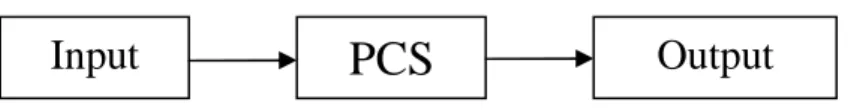
PCS can be classified into two categories, Open Loop Systems (OLS) and Closed Loop Systems (CLS). OLS is one in which the control action is dependent of the output. Figure 1 shows the basic block diagram of OLS [3].
Fig. 1 Open loop system
Some features of an open loop system are simple construction and ease of maintenance. It is less expensive than a corresponding CLS and has no stability problems. Disturbances and changes in calibration result in errors and the output may be different from desired. To maintain the quality of output recalibration is required from time to time.
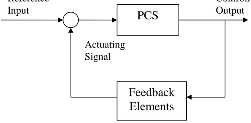
CLS is one in which the control action is somehow dependent on the output. Figure 2 shows the basic block diagram of a CLS.
These are usually called feedback control systems. Feedback is the property of a closed loop systems which permits the output (or some other controlled variable of the system) to be compared with the input to the system (or an input to some internally situated component or subsystem of the system) so that appropriate control action may be performed as some function of input and output. A cause and effect relationship exits between the system variables [4]. Some features of a closed loop systems are increased accuracy, reduced error, reduced sensitivity, reduced effect of nonlinearity and tendency toward oscillation and instability.
Fig. 2 Closed loop system
2. AUTOMATION
Automation relates with feedback control of process variables. Process automation deals with the automatic control of process variables such as flow, temperature, level, pressure, humidity, concentration, etc. The automatic control of the process variables refers to the regulation of these variables in the true sense. This means that any change in the process variable is brought to zero. In other words, the process variable is first sensed or measured and compared with a desired value. The error generated is then processed and fed to the system in such a way that the actual process variable reaches the desired value. Any change in the actual process variable shall render change in error which will drive the system to compensate for the change. Thus process automation is essentially an error actuating mechanism [5].
Automatic control has played a vital role in the advancement of engineering and science. An automatic controller compares the actual value of the system output with the reference (desired value); it determines the deviation, and produces a control signal that will reduced the deviation to zero or to a small value. The manner in which the automatic controller produces the control signal is called control action. The basic control actions are [6]:
1. Two Position or On-Off Control 2. Proportional (P) Control
3. Proportional + Integral (PI) Control 4. Proportional + Derivative (PD) Control
5. Proportional + Integral + Derivative (PID) Control
PCS
Feedback
Elements
Reference Input Controlled Output Actuating Signal3. PROCESS CONTROL TRAINER TYPES
Nowadays, Industrial Control and Mechatronic Education can be done various places on the world. In Turkey, at the level of pre-graduate Mechatronic Education was started in late 90s. For the 2008 – 2009 Academic year there are mechatronic program in 15 Vocational Colleges in Turkey. Today, at the level of graduate 5 Engineering Faculties and one Technical Education Faculty include mechatronic department in Turkey. There is a “Mechatronic Education Department” in Marmara University Technical Education Faculty [7].
Certainly understanding of basic automatic control actions are need process control devices. In generally this trainer based on level, pressure, flow and temperature control. Mostly they have use analog inputs and (level, pressure, etc.) analog outputs (SSR relay, proportional valve, pump motor driver, etc,), on-off, PID control, as a control action. A lot of in these trainers can be use PC connection and SCADA control systems. Some models are presented as below (Fig. 3,4,5,6):
Fig. 5 Pressure Control Trainer [10] Fig. 6 Temperature Control Trainer [10]
4. DESIGNING OF MULTI PROCESS CONTROL TRAINER 4.1 Trainers’ Construction
Control labs can be crowded when in use all together four basic process control trainers (pressure, flow, temperature and level). To solve this problem it can be use modular and multi purpose control trainers. Thus we design a multi process control trainers which it is very cheap and very simple construction.
This trainer is a pioneer application of basic control methods which level, pressure, flow and temperature. Moreover it can be done different control actions on the trainer (Fig. 7 and Fig. 8). Besides to be joined a float control at these control actions.
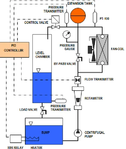
Fig. 7 Block diagram of multi process control trainer
The Multi Process Control Trainer (MPCT), a cupboard size laboratory model on a movable trolley is configured as shown in Fig. 7. The body is made of aluminum sigma profile. The steel panels are coated electrostatic powder. The MPCT consists of a level chamber, an expansion tank, a fan coil and a sump. The water sump on is located the bottom level. The sump has a water heater. Water is sucking from sump by the circulation pump, it then pumping to fan-coil and level chamber by thorough on the rota-meter type flow meter. A control valve is located upper side of water line and it controls water level and flow rate. The MPCT has two pressure transmitters. The upper pressure transmitter is sense water head pressure, then convert analog signal and transmit to the controller. The lower pressure transmitter is sense water pressure in the level chamber. An expansion tank allows head pressure rise. A load valve is located under the level chamber that it provided level load. A temperature sensor (PT-100) is located upper side of fan-coil and it sense water temperature which it come from fan-coil. Heat load is put out by the fan coil, thus water is cools while passed on the fan-coil. A by-pass valve is located in parallel line of the fan-coil, it is diverting
the water to the fan-coil for is forming of temperature control. Lastly the flow transmitter is sense water flow rate, then it convert analog pulse signal and it is transmit to the controller.
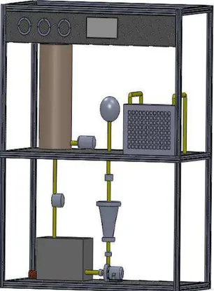
Fig. 8 Multi process control trainer
4.2Controller Structure
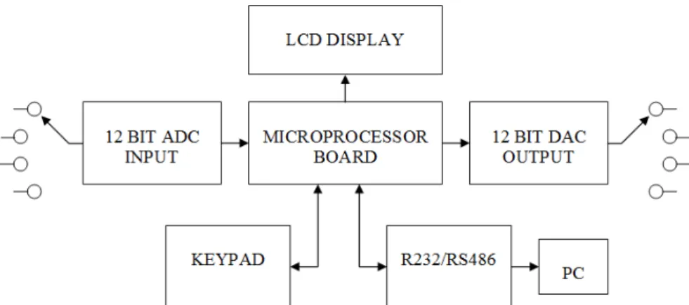
This controller (NC200) was designed for educational purposes by Endkon Ltd [11]. Specifications of NC200 are listed Table 1 and diagram illustrated Figure 9 and 10.
Dimension 800x600x1400 Input 0-10 Volt, 4-20 mA Output 0-10 Volt, 4-20 mA Communication RS 232
Processor 16 bit DSP
Memory 32 Kbytes EEprom Control Actions On-off, P, PI, PD, PID
Fig. 9 Control flow chart
Fig. 10 Front Panel of Controller
5. SOFTWARE SUPPORT
VisiDAQ 3.1 is an easy to use, integrated, industrial monitoring and control software system which is a Windows-based data acquisition, control, analysis and presentation development software package. In addition to typical human machine interface (HMI) functions, VisiDAQ 3.1 features a Visual Basic programming environment, and it provides numerous graphical control and display icons to assist in developing your HMI. Users can arrange control and display icons by dragging and dropping them on screen, resulting in a dynamic, real-time display of process data. Most data acquisition and control systems can be implemented
quickly through this graphical design and presentation system [12]. Features are listed as below:
• Microsoft Windows 3.1/95 platform
• Open real-time data center
• Visual Basic compatible script programming
• Simultaneously performs multiple monitoring and control tasks
• Object-oriented graphics
• Graphical icon (Drag and Drop) programming
• Configurable report designer
• Real-time display/calculation/control
• Real-time & historical trending
• Password protection
• Alarm/event handling
• Dynamic Data Exchange (DDE)
• OLE automation
• User defined DLL
• LAN communications
5.1 Process Monitoring
It interfaces to wide variety of process variables types, such as 0-10 VDC analog voltage and 4-20 mA current, discrete I/O, RTDs, counter and frequency inputs. Thermocouple and RTD linearization are handled by the software. Other variable types include RS-232 devices, time, replay and stored data. Analog and digital inputs are supported as is the pulse input for frequency devices such as a flow transmitter and tachometer.
5.2 Data Logging
Process data can be monitored on a continual basis. As data is collected, values, tag names, and alarm conditions are time stamped and stored. Data can also be displayed and logged as it is acquired, as a function of time-of-day, or as a result of a decision made by the operator or by the system.
of a calculated variable or operator action. The system can be configured so that when an alarm occurs, the operator is notified and must acknowledge the condition.
5.4 Process Control
It provides control functions allow for the turning on and off of equipment for control applications or to indicate alarm conditions. Its PID loops provide closed loop control for constant or variable set points. Set points can be entered through the keyboard, automatically through on-line calculations, or as a preset schedule of values stored on the computer’s disk. It allows tuning of control loops on-line. Control parameters-upper and lower alarm limits, gain, reset, scan rate and set points of the PID algorithms-can be adjusted manually from the keyboard.
5.5 Real-Time Operator Interface
Its flexible operator interface allows for the easy configuring of the system using menu driven set-up screens. For process diagram display, it allows drawing program. One can animate the control strategy in real-time by graphically creating production flows or physical layouts of the system.
5.6 Real-Time Display
It allows the display of process data in any variety of formats. They include, trend line (variable versus time), X-Y graph (variable 1 versus variable 2) and control faceplates.
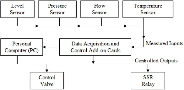
5.7 Sensors and Transmitters
Temperature sensor and transmitter sense the temperature with help of a PT-100 type RTD whose material is made of Platinum. It is provided by resistant change to give the desired analog value of current which serves as a measure of the temperature (Fig. 11).
The flow sensor and transmitter sense the flow with the help of a turbine type flow meter which uses an optical source and detector. The output of detector is a train of pulses which is converted into a corresponding analog voltage using a frequency to voltage converter.
The pressure sensor and transmitter sense pressure with help of strain gage. It has got a wide range of applications. It can be used for measurement of force, torque, pressure, acceleration and many other parameters. The basic principle of operation of a strain gage is simple: when strain is applied to a thin metallic wire, its dimension changes, thus changing the resistance of the wire. Let us first investigate what are the factors, responsible for the change in resistance [13].
The level sensor and transmitter sense level with help of strain gage. Thus a pressure transmitter can be use as a level sensor. Sometimes can be uses an ultrasonic sensor. It sense water level with help of an ultrasonic sound.
Fig. 11 Flow of signals
6. EXPERIMENTAL SET-UPS
Various experimental set-ups were configured for the trainer and executed. Firstly we can select a process type which it can be level, pressure, flow and temperature. Then we can select a control action type is as follows:
1. Two position control (ON-OFF) 2. Float control
3. Proportional (P) control
6. Proportional, integral and derivative (PID) control
Totally it can be made 24 different experimental setups. One of the experimental setups is as follows:
A) NUMBER OF THE EXPERIMENT: MPCT-06
B) NAME OF THE EXPERIMENT: Proportional, integral and derivative Control
(PID) of the level
C) PURPOSE OF THE EXPERIMENT: To understand why integral and derivative times join together to the fault signal (e) on the proportional control.
D) TOOLS AND DEVICES:
E) CONDUCTING COMPONENTS THE EXPERIMENT: 1) Turn on the main switch
2) Turn on the pump by switching on the fuse
3) Entering the SET value of the device chose the automatic status
4) Chose PID option from the automatic status and enter the proportional gain as 50% and integral time as 5 seconds.
5) Adjust the derivative time to 5
6) Watch the reaction time of the system and differentiations on the processing variables
7) Change the integral and derivative times to 10 seconds and watch the differences
8) Repeat the above action this time with 15 seconds
Measured feature / number of the measurement 1 2 3 Set point (SP) [cm] 40 40 40 Process variable (PV) [cm] Proportional gain Kp=0.5 Integral time 5 10 15 Derivative time 5 10 15
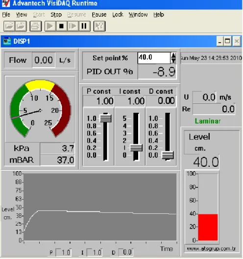
F) WHAT SHOULD BE IN THE REPORT: Number of the experiment, the name and the purpose of the experiment, table values and characteristic curve (Fig. 12).
Fig. 12 PID level control experiment results on the PC
7. CONCLUSION
The MPCT provides user with the practical ascent of Process Control, Intelligent Instrumentation, Automation and Interfacing the PC with real time processes. Experimental setups have been configured on the MPCT to observe the various types of control actions and automate processes on the trainer. It can be done on the MPCT all basic control processes as a level, pressure, flow and temperature. In addition to basic control actions, as on-off, P, PI, PD and PID, can be use the float control action. The Float Control takes a part to On-Off Control and Proportional Control. The MPCT has been successfully designed, developed and applied for automation.
REFERENCES
[1] K. Ogata, (2001), Modern Control Engineering, 4th ed., Prentice Hall 2001.
[2] J.J. Distefano, A.R. Stubberud, & I.J. Williams, Feedback and Control Systems, McGraw Hill 1967.
[3] D. Patranabis, Principles of Process Control, McGraw-Hill Education 1982.
[4] D.R. Coughanowr, Process Systems Analysis and Control, 2nd ed., McGraw-Hill Higher Education. 1991.
[5] B. Kuo & F. Golnaraghi, Automatic Control Systems, 8th ed., Wiley. 2002. [6] P. Harriott, Process Control, Krieger Publishing Co. 1983.
[7] H. Bulgurcu, Development of flow control trainer for mechatronic and industrial control education, UPTRONİC Project Summer School, Opole University, Wisla, Poland, 27 September-2 October 2009.
[8] http://www.sapengineers.co.in/1-pcst-01-flow-control.pdf (was reached date 25.05.2010). [9] http://www.sapengineers.co.in/2-pcst-02-level-control.pdf (was reached date 25.05.2010). [10] http://www.gunt.de (was reached date 29.05.2010).
[11] http://www.endkon.com.tr (was reached date 28.05.2010).
[12] http://www.advantech.gr/ia/111.htm (was reached date 26.05.2010).
[13]
![Fig. 5 Pressure Control Trainer [10] Fig. 6 Temperature Control Trainer [10]](https://thumb-eu.123doks.com/thumbv2/9libnet/5971053.124946/5.892.490.740.102.456/fig-pressure-control-trainer-fig-temperature-control-trainer.webp)