Near field imaging in microwave regime using double layer split-ring
resonator based metamaterial
K. GUVEN
*1,2and E. OZBAY
1,2,31
Nanotechnology Research Centre, Bilkent University, 06-800 Ankara, Turkey
2Department of Physics, Bilkent University, 06-800 Ankara, Turkey
3
Department of Electrical and Electronics Engineering, Bilkent University, 06-800 Ankara, Turkey
A planar metamaterial structure consisting of two layers of split-ring resonator (SRR) arrays is demonstrated to form the im-age of a point source with subwavelength resolution. The source frequency is swept through the resonance gap of the metamaterial layers and the lateral field intensity distribution is recorded on the transmission side of the metamaterial. When the source is tuned to the resonance frequency of SRRs, the metamaterial acts as a high permeability medium and a distinct image with subwavelength resolution in the lateral direction is obtained. Increasing the distance between the individual SRR layers reduces the interlayer coupling, and the intensity and spatial resolution of the image decrease rapidly.
Keywords: metamaterial, subwavelength imaging, near field imaging.
1. Introduction
The intriguing electrodynamics of materials with simulta-neous negative dielectric permittivity e and negative per-meability µ were proposed and discussed by Veselago [1]. Decades after, the pioneering works of Pendry et al. opened the way for the practical realization of artificial ma-terials with the aforementioned electromagnetic properties at different wavelength regimes of the electromagnetic spectrum, for which no naturally occurring material is known to exist [2,3]. In particular, the imaging capabilities of the metamaterials are envisaged as tools which can change the paradigm of microwave and optical imaging de-vices, since they can overcome the diffraction limit of con-ventional lenses [4]. The present studies are focused mainly on two areas, i.e., the development and analysis of meta-materials as lenses having negative effective index of re-fraction and as subwavelength diffracting devices in the near field zone. While the former is closer to the behaviour of a conventional focusing lens, the anisotropic dispersive characteristics of the metamaterials prohibited the practical realization so far [5,6]. Nevertheless, there are some exper-imental reports indicating the lensing behaviour [7]. The latter approach makes use of the metamaterial as the nega-tive high permittivity e or the permeability µ medium to operate in the near field zone, as proposed in Ref. 4. If the system is located in the near field zone (in which all dimen-sions are smaller than the wavelength of light), the electro-static limit may be applied, and hence the electric and mag-netic response of the medium can be treated decoupled.
In-deed, a number of theoretical and experimental studies based one < 0 or µ < 0 metamaterials reported promising results in terms of imaging in the microwave regime [8–14], magnetic resonance imaging (MRI) [15], and even in submicron regime [16].
In this work, we investigate the imaging properties of a layered metamaterial consisting of 2D array of split-ring resonators (SRRs) in the microwave regime. A similar metamaterial lens employing broad side coupled split ring resonators and working by the magneto-inductive coupling was recently reported to provide subwavelength imaging [11]. Here, we consider edge coupled SRRs and show that the resonance of the SRR can be induced via the electric field component of the source provided that the asymmetric geometry of the SRRs on the metamaterial planes are prop-erly oriented. The relation between the subwavelength re-solved image formation and the SRR resonance is clearly demonstrated by spectral measurements.
2. Experiment and analysis
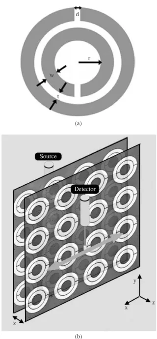
The SRR units are fabricated on FR4 circuit boards (thick-ness 1.6 mm, dielectric constantå = 4.4) with a deposited copper layer of 30-µm thickness. The geometric parameters of the SRR depicted in Fig. 1(a) are d = t = 0.2 mm, w = 0.9 mm, and r = 1.6 mm. The SRR units form a 2D array with periodicity ax = ay = 8.8 mm. This SRR structure is
re-ported to provide a magnetic resonance (µ < 0) around 3.7 GHz and was successfully utilized in a metamaterial which has a left-handed (i.e., negative refractive index) transmis-sion band at this frequency [17]. The fabricated layer con-tains 15 and 18 SRR units in the x, and y directions,
respec-Opto-Electron. Rev., 14, no. 3, 2006 K. Guven
213
OPTO-ELECTRONICS REVIEW 14(3), 213–216
DOI: 10.2478/s11772-006-0028-7
tively. The metamaterial consists of two SRR layers; sepa-rated by a distance z. Figure 1(b) shows schematically the measurement setup for the imaging experiment. A mono-pole source is fixed at 5 mm away from the centre of the first SRR layer. Another monopole serves as the detector, scanning the field intensity along the other (transmission) side of the second SRR layer, at a distance of 5 mm. The metamaterial and the detector are both located in the near field zone of the source. The separation between the layers is made adjustable by a mechanical slider up to 30 mm. The source and detector are connected to a network analyser for measuring the transmission spectrum. In Fig. 1(b), the ordering of the experimental components from back to front are SOURCE – PCB – SRR – z – PCB – SRR – DETECTOR. Note, that the SRR units are not separable from their respective PCB layers. We have defined the interlayer spacing z, such that z = 0 corresponds to the case when the SRRs of the first layer are in contact with the PCB of the second layer. Thus, when z = 0, the two SRR layers are still separated by a PCB layer of thickness 1.6 mm, and the (minimum) separation between the source and detector is 13.2 mm (10 mm + 2PCB layers). Different configurations are possible, e.g., SRR layers are facing each other or away from each other. When the SRR layers face each other, z = 0 would imply that the SRRs are elec-trically in contact which is not desired. In either case, the imaging properties discussed further below would show some changes for each configuration but the essential con-clusions of the study remain valid.
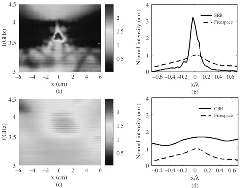
In the configuration depicted in Fig. 1(b), the electric field vector is perpendicular to the splits of SRRs. This causes an imbalance of the charge distribution in each ring, which then induces circulating currents on the rings. The result is a resonant electric response of the SRR de-termined by the capacitance of the splits and inductance between the concentric rings. When the SRR is located in the near field zone of a source which radiates at resonance wavelengths of the SRR, the propagating and, in particu-lar, the evanescent modes of the radiation can couple to the SRRs and transferred spatially through the meta-material to the image plane. A near field probe on the transmission side of the metamaterial would then be able to detect the source with subwavelength resolution. The spectral and spatial properties of the image are investi-gated by sweeping the source frequency across the reso-nance gap of SRRs, and by scanning the lateral intensity profile. Figure 2(a) shows the measured intensity map in colour scale for z/ë = 0. Within the gap, a distinct peak profile is observable in the spatial direction at around
f = 3.7 GHz. Indeed, the lateral intensity profile (solid
line) plotted in Fig. 2(b) shows that the metamaterial can form the near field image of the source with substantial enhancement in both the intensity and spatial resolution when contrasted to the intensity profile in the absence of the metamaterial (dashed line). The full width half max (FWHM) of the intensity is approximately 0.15ë.
In order to make the connection of image formation with the resonance of SRRs, we made a control experiment using closed-ring (CRR) structures. Since the splits are ab-sent in the CRR, no capacitance is preab-sent in the rings and a resonance behaviour is not available in contrast to SRR [17]. Figure 2(c) shows the spectral distribution of the lat-eral intensity for the control experiment. In this case a re-solved image of the source is not present. Apparently, the CRRs degrade the image further by diffraction as seen in the lateral profiles given in Fig. 2(d). The overall slight en-hancement of the signal with respect to freespace propaga-tion can be attributed to the refracpropaga-tion by the circuit board having a larger dielectric constant than air.
Near field imaging in microwave regime using double layer split-ring resonator based metamaterial
214
Opto-Electron. Rev., 14, no. 3, 2006 © 2006 COSiW SEP, WarsawFig. 1. The split-ring resonator structure (a). The parameter values are d = t = 0.2 mm, w = 0.9 mm, and r = 1.6 mm. Schematic view of the experimental setup consisting of source and detector monopoles, and the two layers of SRR metamaterial (b). The
Opto-Electron. Rev., 14, no. 3, 2006 K. Guven
215
Fig. 2. The spectral map of the lateral field intensity distribution for double layer SRR metamaterial (a). The interlayer spacing is z = 0.0 mm. The intensity is normalized by the maximum of the intensity for freespace propagation at z = 0 and x = 0. Lateral cross section of the field intensity at f = 3.7 GHz in the presence of double layer SRR metamaterial (solid lines) and in the absence (i.e. freespace) (dashedlines) (b). Same as in case (a) using CRR metamaterial (c). Same as in case (b) using CRR metamaterial (d).
Fig. 3. Spectral map of the lateral field intensity distribution for double layer SRR metamaterial for different amounts of interlayer spacing. The intensity color map is calibrated with respect to the freespace propagation taken when z = 0 (hence the intensity values larger than
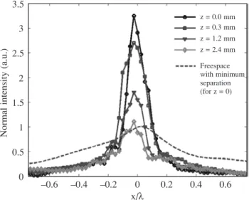
The spectral measurement for the SRR metamaterial is repeated by varying the distance between the SRR layers. The spectral-spatial intensity maps are plotted in Fig. 3. In-creasing the interlayer distance, decreases the coupling be-tween the layers and the SRR resonance band shrinks from ~0.9 GHz for z = 0.0 mm to ~0.6 GHz for z = 2.4 mm. At the same time, the intensity of the focused image rapidly decreases. We also note that all the intensity maps plotted in Fig. 3 are normalized by the maximum of the freespace propagation profile for z = 0, at the centre point (x = 0) of the spatially scanned region. Thus, the intensity plots for z
¹ 0 are actually suppressed in magnitude, since they are not
normalized by their respective freespace measurement. It should be noted that the freespace profile degrades faster than that observed in the presence of SRR layers, since the evanescent modes do not acquire any enhancement in freespace at all. Figure 4 shows the lateral intensity profiles at f = 3.74 GHz obtained from the data in Fig. 3. The rapid decrease in the intensity and the broadening of the profile are observed.
3. Conclusions
In conclusion, we investigated experimentally the near field image formation by a metamaterial consisting of dou-ble layer arrays of split-ring resonators. For a monopole source radiating at the resonance frequency of SRR and lo-cated close to the metamaterial surface, the electric field coupling to the SRR induces the resonance and the image of the source can be formed on the transmission side. The full width half max of the image profile is found to be 0.15 ë, well within the subwavelength regime. The image resolution is quite sensitive to the interlayer spacing of the double layer metamaterial.
References
1. V.G. Veselago, “The electrodynamics of substances with si-multaneously negative values ofå and µ”, Sov. Phys. Usp. 10, 509–514 (1968).
2. J.B. Pendry, A.J. Holden, D.J. Robbins, and W.J. Stewart, “Extremely low frequency plasmons in metallic mesostruc-tures”, Phys. Rev. Lett. 76, 4773–4776 (1996).
3. J.B. Pendry, A.J. Holden, D.J. Robbins, and W.J. Stewart, “Magnetism from conductors and enhanced nonlinear phe-nomena”, IEEE Trans. Microwave Theory Tech. 47, 2075–2084 (1999).
4. J.B. Pendry, “Negative refraction makes a perfect lens”, Phys. Rev. Lett. 85, 3966–3969 (2000).
5. N. Garcia and M. Nieto-Vesperinas, “Left-handed materials do not make a perfect lens”, Phys. Rev. Lett. 88, 207403 (2002).
6. D.R. Smith, D. Schurig, M. Rosebluth, S. Schultz, S. Anantha-Ramakrishna, and J.B. Pendry, “Limitations on subdiffraction imaging with a negative refractive index slab”, Appl. Phys. Lett. 82, 1506–1508 (2003).
7. K. Aydin, I. Bulu, and E. Ozbay, “Focusing of electromag-netic waves by a left-handed metamaterial flat lens”, Opt. Exp. 13, 8753–8759 (2005).
8. N. Fang, and X. Zhang, “Imaging properties of a metamaterial superlens”, Appl. Phys. Lett. 82, 161–163 (2003).
9. A.N. Lagarkov and V.N. Kissel, “Near-perfect imaging in a focusing system based on a left-handed-metamaterial plate”, Phys. Rev. Lett. 92, 077401 (2004).
10. S. Maslovski, S. Tretyakov, and P. Alitalo, “Near-field en-hancement and imaging in a double planar polariton-reso-nant structures”, J. Appl. Phys. 96, 1293–1300 (2004). 11. R. Marqués, F. Mesa, and F. Medina, “Near field enhanced
imaging by a magnetized ferrite slab”, Appl. Phys. Lett. 86, 023505 (2005).
12. M.J. Freire and R. Marqués, “Planar magnetoinductive lens for three-dimensional subwavelength imaging”, Appl. Phys. Lett. 86, 182505 (2005).
13. F. Mesa, M.J. Freire, R. Marqués, and J.D. Baena, “Three dimensional superresolution in metamaterial slab lenses: Experiment and theory”, Phys. Rev. B72, 235117 (2005). 14. P. Alitalo, S. Maslovski, and S. Tretyakov, “Near-field
en-hancement and imaging in double cylindrical polariton-resonant structures: Enlarging perfect lens”, http:// arxiv.org/abs/physics/0509232.
15. M.C.K. Wiltshire, J.V. Hajnal, J.B. Pendry, D.J. Edwards, and J.C. Stevens, “Metamaterial endoscope for magnetic field transfer: near field imaging with magnetic wires”, Opt. Exp. 11, 709–715 (2003).
16. D.O.S. Melville, R.J. Blaikie, and C.R. Wolf, “Submicron imaging with a planar silver lens”, Appl. Phys. Lett. 84, 4403–4405 (2004).
17. K. Aydin, K. Guven, M. Kafesaki, L. Zhang, C.M. Soukoulis, and E. Ozbay, “Experimental observation of true left-handed transmission peaks in metamaterials”, Opt. Lett. 29, 2623–2625 (2004).
Near field imaging in microwave regime using double layer split-ring resonator based metamaterial
216
Opto-Electron. Rev., 14, no. 3, 2006 © 2006 COSiW SEP, WarsawFig. 4. Lateral cross section of the field intensity at f = 3.7 GHz taken from Fig. 3. The freespace measurement is taken when z = 0, and the SRR metamaterial was removed. In this case, the separation