Electrically small split ring resonator antennas
Kamil Boratay Alici, and Ekmel Ozbay
Citation: Journal of Applied Physics 101, 083104 (2007); doi: 10.1063/1.2722232 View online: http://dx.doi.org/10.1063/1.2722232
View Table of Contents: http://aip.scitation.org/toc/jap/101/8
Published by the American Institute of Physics
Articles you may be interested in
Split-ring resonator for use in magnetic resonance from 200–2000 MHz
Review of Scientific Instruments 52, 213 (1998); 10.1063/1.1136574
Split ring resonator-based left-handed coplanar waveguide
Applied Physics Letters 83, 4652 (2003); 10.1063/1.1631392
Split ring resonator sensors for infrared detection of single molecular monolayers
Applied Physics Letters 95, 043113 (2009); 10.1063/1.3194154
Electromagnetic resonances in individual and coupled split-ring resonators
Journal of Applied Physics 92, 2929 (2002); 10.1063/1.1497452
Tuned permeability in terahertz split-ring resonators for devices and sensors
Applied Physics Letters 91, 062511 (2007); 10.1063/1.2768300
An antenna-coupled split-ring resonator for biosensing
Electrically small split ring resonator antennas
Kamil Boratay Alicia兲 and Ekmel OzbayNanotechnology Research Center, Department of Physics,
Department of Electrical and Electronics Engineering, Bilkent University, 06800 Ankara, Turkey
共Received 21 January 2007; accepted 26 February 2007; published online 20 April 2007兲
We studied electrically small resonant antennas composed of split ring resonators 共SRR兲 and monopoles. The antennas considered have the same ring radius, but slightly different geometry. The resonance frequency depends on the geometry of the SRRs. Two SRR antennas are designed. The first one, which operates at 3.62 GHz, is demonstrated theoretically and experimentally. The size of this antenna is 0.0950⫻0.1000 and is low profile at the other dimension. The gain and
directivity of the antenna was 2.38 and 5.46, respectively. The corresponding efficiency was 43.6%. The estimated radiation Q 共rad Q=23.03兲 was much larger than the minimum radiation
Q共min Q=1.78兲. The second one is a rather small SRR antenna in which the capacitance between
the rings is increased. The size is reduced to 0.0740⫻0.0790. This structure is called serrated SRR共SSRR兲. Both antennas have similar far-field patterns but the efficiency of the SSRR antenna is less. © 2007 American Institute of Physics.关DOI:10.1063/1.2722232兴
I. INTRODUCTION
Electrically small antennas共ESAs兲 occupy a volume of the sphere whose radius is a small fraction of the free-space wavelength of the radiated electromagnetic field.1 The fun-damental limitations of ESAs were investigated by Wheeler in 1947.2One year later, Chu derived a theoretical relation-ship between the dimensions of an antenna and its minimum quality factor.3Fundamental limitations of antennas are still an active research area.4–6The general techniques applied in order to achieve these theoretical limits are the optimization of the antenna topology7,8 and usage of magneto-dielectric materials.9,10
Artificial materials that exhibit unusual physical proper-ties attracted much attention in the last decade of the last century.11Can the introduction of these materials into anten-nas improve the current performance, especially in terms of their rather small size? The invention of antennas, which resonantly couple to external radiation, composed of single negative materials is a rather interesting study.12 Moreover, research on obtaining an electrically small size by using metamaterials has been presented in the literature recently.13–17 Eleftheriades et al. proposed a metamaterial ring antenna of efficiency 54% 共Ref. 16兲 and Stuart et al. theoretically demonstrated an electrically small antenna with
ka⬍0.5.17
One of the most important elements of metamaterials is the split ring resonator 共SRR兲, which was designed by Pendry et al. in 1999.18 The geometrical parameters of this structure determine its resonance frequency. The SRR can show resonant behavior at wavelengths that are much larger than its own size. Experimental demonstrations of these structures have been achieved by many researchers.19–21 In the present work, we explain a technique that uses the SRRs in order to obtain ESAs.
II. EXPERIMENT
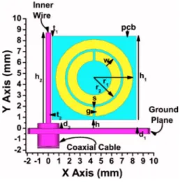
The SRR is electrically excited with a monopole an-tenna. The configuration is shown in Fig. 1, in which the geometrical parameters of the structure are as follows: outer ring radius r1= 3.6 mm, inner ring radius r2= 5 mm, width of
the strips w = 0.9 mm, separation between the two adjacent rings s = 0.2 mm, the length of the splits g = 0.2 mm. Distance to the ground plane h = 0.8 mm, the distance of the end of the radiating inner wire part to the top of the printed circuit board共PCB兲 t1= 0.2 mm, the distance between the PCB and radiating inner wire part of the monopole t2= 0.1 mm, thick-ness of the ground plane d1= 0.5 mm, length of the coaxial cable above the ground plane 共this part was necessary for physically strengthening the monopole兲 d2= 0.5 mm, PCB
side length h1= 7.8 mm, and inner wire height h2= 8.32 mm.
The coaxial cable has four major parts: the inner wire with a radius of 0.245 mm, Teflon part with a thickness of 1.08 mm, and a dielectric constant 2, conducting shield part with a thickness of 0.48 mm and insulator coating with 0.48 mm thickness.
a兲Electronic mail: [email protected] FIG. 1. The geometry of the SRR antenna is shown, but only a part of theground plane and the coaxial cable.
The substrate PCB was standard FR-4 material with rela-tive permittivityr= 3.5. The thickness of the PCB was 1.6 mm and the deposited copper thickness on the PCB was 30m. SRR was obtained by properly etching the metal deposit of the PCB. The ground plane is nearly square-shaped at the x-z plane, with the square side length being
equal to the free-space wavelength共0兲 at the operation
fre-quency 共f0兲. The operation frequency is selected to be the frequency at which the SRR shows resonant behavior. This frequency is determined as 3.62 GHz by considering the minimum of the input reflection coefficient, S11. The antenna is simulated by using the commercial software Computer Simulation Technology, Microwave Studio共CST MWS兲, which is based on the finite integration method. The experiments are performed via an HP8510C network analyzer. The simu-lation and experiment data of the S11are presented in Fig.2.
The minimum of the S11 data of the reflection experiment
was⫺32 dB.
III. RESULTS AND DISCUSSION
The overall size of the antenna part is 0.0950
⫻0.1000. Since the antenna part is above a conducting
plane while defining the radius of the minimum sphere that encloses the antenna, we should also, therefore, consider the antenna’s image.6Therefore, the minimum radius a for our antenna is 0.1440, i.e., 11.95 mm.
FIG. 2. S11of the SRR antenna, experiment, and simulation
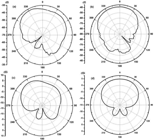
FIG. 3. Far-field radiation patterns of the SRR antenna.共a兲 E-plane measured 共x-y plane兲; 共b兲 H-plane measured 共y-z plane兲; 共c兲 E-plane simulated; 共d兲
H- plane simulated.
The radiation quality factor of an ESA is of fundamental interest. It is defined as 2 times the ratio of the maximum energy stored to the total energy lost per period.3,4 We esti-mate the minimum radiation Q of our antenna by using the following equation:4 Q =1 2
冉
1 k3a3+ 2 ka冊
, 共1兲where k is the wave number associated with the electromag-netic field operating at f0frequency. Therefore, we estimate
the minimum radiation quality factor of the antenna as min Q = 1.78.
The Q of the antenna was calculated by using the Fos-ter’s reactance theorem.5 The fractional bandwidth 共FBW兲 and⫺10 dB BW are obtained from the experimental S11data as 0.043 and 2.42%, respectively. Therefore, the Q⬃1/BW is 23.03 and is adequately large22 and well above the theo-retical limit.
The far-field radiation pattern measurements were per-formed by using a standard gain horn antenna as a receiver. The distance between the antennas was⬃1 m, which corre-sponds to the far-field region for our antenna. The measured and simulated copolarized E- and H-plane far-field radiation patterns are presented in Fig. 3. We see that the simulated and measured far-field patterns are similar; however, the simulation predicts symmetric sidelobe levels for the
H-plane pattern. We were unable to see this symmetry due to
experimental limitations. The value of the maximum direc-tivity is approximately equal to23
D0= 41 253 ⌰1d⫻ ⌰2d
, 共2兲
where⌰1dis the half-power beamwidth in one plane and⌰2d
in the perpendicular plane to the first, in degrees. The
mea-sured half power beamwidth was 76° along the E-plane and was 92° along the H-plane. The absolute gain measurements are followed by the two antenna method calculations, in which we obtained the antenna gain as G = 2.38. The corre-sponding radiation efficiency of the antenna was 43.6%. The figures of merit of the antenna obtained from the measure-ments and simulation are summarized in Table I.
Finally, we should compare the gain of our antenna with the fundamental limit given by Fante.24The maximum pos-sible gain for our antenna estimated from the Fante’s analysis is 4.51. We see that our gain is less than the theoretical limit. If we can excite the SRR electrically at rather small fre-quencies, the antenna size can be further miniaturized since the SRR resonance frequency can be tuned by increasing the capacitance between the rings. Considering this fact we de-signed serrated SRR, which has a resonance at 2.84 GHz. Just by changing the shape of the rings as shown in Fig.4we obtained a smaller SRR antenna. However, though the size is smaller, the maximum theoretical gain is thereby reduced to 2.33. Correspondingly, the antenna efficiency was then 18.8%. The calculated figures of merit are presented in Table I. The simulation results for the insertion loss and the far-field radiation patterns are shown in Figs. 4 and5, respec-tively.
IV. CONCLUSION
We conclude that metamaterials can play a role in the development of ESAs. By electrically exciting the SRRs placed on a ground plane we were able to obtain resonant antennas with efficiencies exceeding 40%. The sizes of the antenna were less than0/ 10.
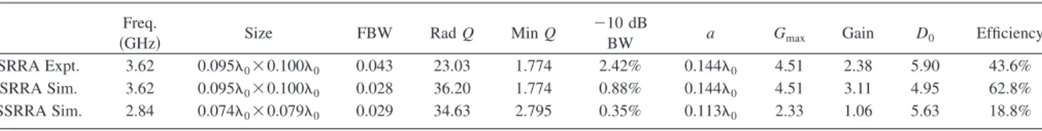
We observed that as we continued decreasing the reso-nant frequency of the SRRs, the maximum theoretical gain and simultaneously the gain decreased. Therefore, we can estimate the limit of our method, which is used to miniatur-TABLE I. The figures of merit of some of the antennas.
Freq.
共GHz兲 Size FBW Rad Q Min Q ⫺10 dBBW a Gmax Gain D0 Efficiency SRRA Expt. 3.62 0.0950⫻0.1000 0.043 23.03 1.774 2.42% 0.1440 4.51 2.38 5.90 43.6%
SRRA Sim. 3.62 0.0950⫻0.1000 0.028 36.20 1.774 0.88% 0.1440 4.51 3.11 4.95 62.8%
SSRRA Sim. 2.84 0.0740⫻0.0790 0.029 34.63 2.795 0.35% 0.1130 2.33 1.06 5.63 18.8%
FIG. 4. 共a兲 Serrated SRR geometry; 共b兲 Return loss for the SSRR antenna and SRR antennas.
ize antennas. Moreover, it is important to note that when excited properly, SRRs above a ground plane radiate effi-ciently. These results can have applications in future wireless systems and in the development of the steerable phased array antennas.
ACKNOWLEDGMENTS
This work is supported by the European Union under the projects EU-DALHM, EU-NOE-METAMORPHOSE, EU-NOE-PHOREMOST, and TUBITAK under Project Nos. 104E090, 105E066, and 105A005. One of the authors 共Ek-mel Ozbay兲 also acknowledges partial support from the Turkish Academy of Sciences.
1R. C. Hansen, Proc. IEEE 69, 170共1981兲. 2H. A. Wheeler, Proc. IRE 49, 1479共1947兲. 3L. J. Chu, J. Appl. Phys. 19, 1163共1948兲.
4J. S. Mclean, IEEE Trans. Antennas Propag. 44, 672共1996兲.
5W. Geyi, P. Jarmuszewski, and Y. Qi, IEEE Trans. Antennas Propag. 48,
401共2000兲.
6J. C. E. Sten, A. Hujanen, and P. K. Koivisto, IEEE Trans. Antennas
Propag. 49, 829共2001兲.
7S. R. Best, IEEE Trans. Antennas Propag. 53, 502共2005兲. 8E. E. Altshuler, IEEE Trans. Antennas Propag. 50, 297共2002兲. 9K. L. Wong, Compact and Broadband Microstrip Antennas共Wiley, New
York, 2002兲.
10K. Buell, H. Mosallaei, and K. Sarabandi, IEEE Trans. Microwave Theory
Tech. 54, 135共2006兲.
11J. Pendry, Nat. Mater. 5, 599共2006兲.
12E. D. Isaacs, P. M. Platzman, and J. T. Shen, U.S. Patent No. 6,661,392共9
December 2003兲.
13S. Hrabar, J. Bartolic, and Z. Sipus, IEEE Trans. Antennas Propag. 53, 110
共2005兲.
14M. E. Ermutlu, C. R. Simovski, M. K. Karkkainen, P. Ikonen, S. A.
Tretyakov, A. A. Sochava, in International Workshop Antenna Technol-ogy: Small Antennas and Novel Metamaterials共IEEE, New York, 2005兲, p. 87.
15P. Ikonen, M. Karkkainen, and S. Tretyakov, Experimental study of a
/2–patch antenna loaded with an array of metasolenoids as artifical mag-netic substrate共IEEE, New York, 2005兲.
16F. Qureshi, M. A. Antoniades, and G. V. Eleftheriades, IEEE Antennas
Wireless Propag. Lett. 4, 333共2005兲.
17H. R. Stuart and A. Pidwerbetsky, IEEE Trans. Antennas Propag. 54, 1644
共2006兲.
18J. B. Pendry, A. J. Holden, D. J. Robbins, and W. J. Stewart, IEEE Trans.
Microw. Theory Tech. 47, 2075共1999兲.
19D. R. Smith, W. J. Padilla, D. C. Vier, S. C. Nemat-Nasser, and S. Schultz,
Phys. Rev. Lett. 84, 4184共2000兲.
20A. A. Houck, J. B. Brock, and I. L. Chuang, Phys. Rev. Lett. 90, 137401
共2003兲.
21O. Moser, B. D. F. Casse, O. Wilhelmi, and B. T. Saw, Phys. Rev. Lett. 94,
063901共2005兲.
22G. A. Thiele, P. L. Detweiler, and R. P. Penno, IEEE Trans. Antennas
Propag. 51, 1263共2003兲.
23C. A. Balanis, Antenna Theory: Analysis and Design共Wiley, New York,
1997兲.
24R. Fante, IEEE Trans. Antennas Propag. 40, 1586共1992兲.
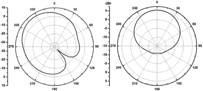
FIG. 5. 共a兲 E- plane and 共b兲 H- plane simulated patterns of the SSRR antenna.