ISTANBUL KULTUR UNIVERSITY
INSTITUTE OF SCIENCES & ENGINEERING
INTEGRATING MOBILE MAPPING,GPS AND GIS
TECHNOLOGIES
An M.Sc THESIS
By
AWAD ALI AWAD ALHADAD
DEPARTMENT OF CIVIL ENGINEERING
Supervised By Assoc. Prof.Dr. Gursel GUZEL
ISTANBULTURKEY
September 2005
GIS TECHNOLOGIES by
AWAD ALI AWAD ALHADAD
Chairperson of the Supervisory Committee:Professor Turgut UZEL Department of Civil Engineering
ABSTRACT
A detailed definition of Global Positioning System (GPS) as given by Wooden 1985] reads: “The Navstar Global Positioning System (GPS) is an all weather, space based navigation system under development by the U.S. Department of Defense (DoD) to satisfy requirements for the military forces to accurately determine their position, velocity, and in a common reference system, anywhere on or near the earth on a continuous basis”.
Despite the main military goal of GPS, it has attracted a broad spectrum of users. Moreover, it has become an essential component of various applications ranging from surveying and mapping as well as precise time determination, vessel navigations and oceanography to international air traffic management [Parkinson et al., 1994].
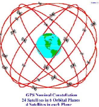
Basically, GPS is comprised of three main segments: the space segment, the control segment and the user segment. The purpose of these segments is to provide continuous reliable positioning and timing services for GPS users. The space segment consists of 24 satellites orbiting around the earth at an altitude of about 20200 km and with a period of Approximately 12 hours as illustrated in Figure 2.1 [Hoffmann-Wellenhof et al., 1994].
Each satellite transmits a signal that includes the navigation messages based on periodically uploaded data from the control segment. The control segment is a set of monitor stations, ground control stations, and a master control station (that is the central control node for GPS operations) and backup master control station. The user segment consists of GPS receivers from wide varieties of manufacturers. These receivers process The received GPS signals and compute the user position.
The GPS reference coordinate system is the World Geodetic System 1984 (WGS-84) [Decker, 1986]. The user’s coordinates are determined in this frame and can then be transformed to other systems. Timing is the heart of GPS; GPS time uses an atomic time scale. GPS time is defined as the number of seconds elapsed from Saturday midnight of the present week. The GPS time was coincident with Universal Time Coordinated (UTC is maintained by the U.S. Naval Observatory USNO) at the GPS standard epoch of January 6, 1980.
GPS time is synchronized with UTC at the microsecond level, within an integer number of seconds. The integer offset between GPS time and UTC arises because of the leap seconds periodically inserted for UTC [Hoffmann-Wellenhof et al., 1994].
Fundamentals of GPS signal structure, observations and error sources, as well as a brief history of the Global Positioning System, Segments of the GPS, A primer on how the GPS works, Problems with the GPS, Advancements in the GPS are presented in the following sections. These fundamentals are directly relevant to the research presented in this thesis.
Mobile mapping has been the subject of significant research and development by several Research teams over the past decade. A mobile mapping system consists mainly of a moving platform, navigation sensors, and mapping sensors. The mobile platform may be a land vehicle, a vessel, or an aircraft. Generally, the navigation sensors, such as GPS (Global Positioning System) receivers, vehicle wheel sensors, and INS (Inertial Navigation System), provide both the track of the vehicle and positional and orientational information of the mapping sensors. Objects to be surveyed are sensed directly by mapping sensors, for instance CCD (Charge Coupled Device) cameras, laser rangers, and radar sensors. Since the orientation parameters of the mapping sensors are estimated directly by the navigation sensors, complicated computations such as photogrammetric triangulation are greatly simplified or avoided. Spatial information of the objects is extracted directly from the georeferenced mapping sensor data by integrating navigation sensor data. Mobile mapping technology has evolved to a stage which allows mapping
information with less time and effort, and high productivity. In addition, a successful Extension of this technology to helicopter - borne and airborne systems will provide a powerful tool for large scale and medium scale spatial data acquisition and database updating. This thesis provides a systematic introduction to the use of mobile mapping technology for spatial data acquisition. Issues related to the basic principle, data processing, automation, achievable accuracies and a break down of errors are given. Application considerations and application examples of the technology in highway and utility mapping are described. Finally, the perspective of the mobile mapping technology is discussed.
ACKNOWLEDGEMENTS
This thesis would not have been possible without the efforts of a large number of other people. Foremost among them Professor Turgut UZEL for his continuous guidance and support every day of my graduate studies, for his patience and his confidence in me, I have learned technology, leadership, and management from him. Dr Gursel GUZEL my supervisor. Professor Kamil EREN from GEOTECH GROUP. Professor Ali Riza GUNBAK the head of Marine Works in STFA Group for his supportive. Dr-Ing. Karsten Jacobsen The head of institute of Photogrammetry and geoinformation at University of Hannover in Germany. Professor Muhammed SAHIN from Istanbul Technical University (ITU). Thanks to all of these for their expertise, friendship and support.
I would like to express my deep appreciation to Professor Hasan KARATS (God mercifulness is upon him) for all his help, insight and encouragement.
I wish to thank my family; I would like to express my deep appreciation to my Father, Ali ALHADAD, my brothers, and sisters for being supportive in every possible way.
Last but definitely not least, I would like to express my deepest gratitude to my wife Mabrouka, for being patient and supportive, despite our busy life the past year with little Lujain.
APPROVALPAGE i ABSTRACT ii ACKNOWLEDGMENT v TABLE OF CONTENTS vi LIST OF TABLES ix LIST OF FIGURES x LIST OF ABBREVIATIONS xi CHAPTER ONE 1 INTRODUCTION 1
1.1 BACKGROUND AND MOTIVATIONS 1
1.2 RESEARCH OBJECTIVES 2
1.3 THESIS OUTLINE 2
CHAPTER TWO: 3
2.1 GPS THEORY OVERVIEW 3
2.2 The Segments Of GPS System 4
2.2.1 Control Segment 4
2.2.2 Space Segment 6
2.2.3 User Segment 9
2.3 Basic Functions of the GPS 10
2.4 GPS Satellite Theory And Signals 10
2.4.1 Position, and Time from GPS 12
2.4.1.1 Receiver Position is Based on Time 13
2.4.1.2 How the Current Locations of GPS Satellites are Determined 14 2.4.1.3 How A GPS Receiver Determines Its Position 14
2.4.1.4 Time from GPS 17
2.5 GPS SURVEY TECHNIQUES 20
2.5.1 Pseudo-Range Navigation 20
2.5.2 Carrier Phase Tracking (Surveying) 21
2.5.3 Differential GPS (DGPS) Techniques (General principals) 22
2.5.3.1 Differential Code GPS (Navigation) 23
2.5.3.2 Differential Carrier GPS (Survey) 23
2.6 Trilateration, How GPS Determines a Location 25
2.6.1 Signals From One Satellites 25
2.6.2 Signals From Two Satellites 26
2.6.3 Three Satellites (2D Positioning) 27
2.6.4 Triangulating Correct Position 28
2.7 The GPS Error Budget 31
2.7.1 Sources of GPS Error 31
2.7.1.1 Selective Availability ( S / A ) 31
2.7.1.2 Satellite clock errors 32
2.7.1.3 Orbit errors 32
2.7.1.4 Ionospheric interference 33
2.7.1.5 Tropospheric interference 33
2.7.1.6 Receiver noise 33
2.7.1.7 Wide Area Augmentation System Accuracy 33
2.7.1.8 Control Segment blunders 35
2.7.1.9 User mistakes 35
2.8 GPS Dilution of Precision and Its Affects On GPS Accuracy 38
2.8.1 Ideal Satellite Geometry 39
2.8.2 Good Satellite Geometry 40
2.8.3 Poor Satellite Geometry 41
2.9 Accuracy And Data Corrections Techniques 44
2.9.1 Accuracy vs Precision 44
2.9.2 Definitions of accuracy 46
2.9.3 Attainable accuracies 46
2.9.4 Positioning Service (PS) 47
2.9.4.1 Precise Positioning Service (PPS) 47
2.9.4.2 Standard Positioning Service (SPS) 48
2.9.5 Improving Accuracy 49
2.9.5.1 Differential GPS (DGPS 49
2.9.5.2 Post processing 51
2.9.5.3 Real-Time Kinematic 52
2.9.6 Wide Area Augmentation System 53
2.9.6.1 Wide Area Augmentation System Accuracy 55
CHAPTER THREE: 56
MOBILE MAPPING SYSTEM 56
3.1 INTRODUCTION ( BACKGROUND ) 56
3.2 OUTLINE 57
3.3 Mobile Mapping System Configuration 58
3.4 Mobile Mapping Infrastructure and architecture 61
3.4.1 Wireless Phones 61 3.4.2 WAP Phones 61 3.4.3 GPRS Phones 61 3.4.4 IMode Phones 62 3.4.5 PDAs 62 3.4.6 PalmOS Devices 63 3.4.7 WindowsCE devices 63 3.4.8 EPOC devices 63 3.4.9 Land Phones 64
3.5 GPS-Aided-INS for Mobile Mapping 64
3.5.1 Introduction 64
3.5.2 Inertial Navigation System (INS) 64
3.5.3 Kalman Filter 65
3.5.4 Advantages of GPS/INS integration 66
3.6.2 Direct GPS integration 68
3.6.3 Indirect Laser/GPS integration 69
3.6.4 Independent Laser Mapping 69
3.7 Mobile Mapping System Selection Considerations 70
3.7.1 GPS Receiver Selection Consideration 70
3.7.2 Data Collector Selection Consideration 70
3.7.3 Laser Range Finder Selection Consideration 70
3.7.4 Software Selection Consideration 71
3.8 Development of Mobile Mapping Systems Technology 72
3.8.1 Photo-Logging 72
3.8.2 Video-Logging 72
3.8.3 Mobile Mapping 73
3.8.3.1 Mobile Mapping vs. Real-Time Mapping 74
3.9 Multi-Sensor Integrated Mobile Mapping Technology 75
3.9.1 Direct Georeferencing 75
3.10 Positioning and Mapping Sensors 77
3.10.1 Positioning sensors 77
3.10.2 Mapping sensors 77
3.11 Accuracy Assessment of Sensors 78
3.11.1 Accuracy of Positioning Sensors 78
3.11.2 Accuracy of Mapping Sensors 79
3.11.3 Accuracy Improvement 80
CHAPTER FOUR 82
SPECIAL APPLICATIONS 82
4.1 Highway Application 82
4.2 Application to Facility Mapping 84
4.3 Application in precision agriculture 86
4.3.1 Precision agriculture 86
4.3.2 Mobile Mapping System in Precision Agriculture 87
4.3.2.1 Improve the Accuracy of Soil Sampling 88
4.3.2.2 Plant Growth, Diseases and Insect Pests Monitor 88 4.3.2.3 Analysis of the Crop and Field Information 89
4.4 Infrastructure mapping for emerging responses 89
4.5 Some Papers on New Developments and Applications of Mobile Mapping Systems 90
4.5.1 New Applications: 90
4.5.2 New Development 92
CHAPTER FIVE 94
CONCLUSION AND RECOMMENDATIONS 94
5.1 CONCLUSION 94
5.2 RECOMMENDATIONS 95
LITERATURES 97
LIST OF TABLES
Table 2.1 Different time offsets for various cities. 19
Table 2.2 GPS Error Budget 37
Table 2.3 Dilution Of Precision( DOP ) 43
Table 2.4 GPS Error Budget With Differential Correction. 51
Table 3.1 Position accuracy of GPS 78
Figure 2.1 Monitor and control stations. 6
Figure 2.2 GPS Nominal Constellation 8
Figure 2.3 GPS Signal Structure 11
Figure 2.4 Radio signal. 13
Figure 2.5 The pseudo random noise (PRN) code. 15
Figure 2.6 Differential GPS Positioning. 24
Figure 2.7 GPS Carrier Phase Positioning. 24
Figure 2.8 Signal From One Satellite. 25
Figure 2.9 Signal From Two Satellite. 26
Figure 2.10 2D Positioning. 27
Figure 2.11 Triangulating Correct Position 29
Figure 2.12 3D Positioning. 30
Figure 2.13 GPS Multipath Errors. 34
Figure 2.14 Sources of Signal Interference. 36
Figure 2.15 Receiver Errors. 37
Figure 2.16 Ideal Satellite Geometry. 39
Figure 2.17 Good Satellite Geometry. 40
Figure 2.18 Poor Satellite Geometry (Set 1). 42
Figure 2.19 Poor Satellite Geometry (Set 2). 42
Figure 2.20 Poor Satellite Geometry (Set 3). 43
Figure 2.21 Accuracy vs Precision. 45
Figure 2.22 Differential GPS. 50
Figure 2.23 Wide Area Augmentation System. 54
Figure 2.24 WASS ACCURACY. 55
Figure 3.1 Mobile Mapping System Configuration 58
Figure 3.2 Mobile (moving) platform 59
Figure 3.3 lllustration of Geo-referencing 60
Figure 3.4 Accessing Map content on devices that can connect to the
internet 63
Figure 3.5 Block Diagram of GPS/INS Integration 66
Figure 3.6 GPS may be blocked by Trees, buildings, and mountains but
INS keeps on working. 67
Figure 3.7 The Laser Range Finder 68
Figure 3.8 Direct and Indirect Laser / GPS Integration 69
Figure 3.9 The concept of direct georeferencing 76
Figure 4.1 Facility Mapping 85
LIST OF ABBREVIATIONS 1-D one-dimensional
2-D two-dimensional
2DRMS two Distance Root Mean Square C/A code Coarse/Acquisition code
DGPS Differential Global Positioning System IGS International GPS Service
IPP Ionospheric Pierce Point ISM Ionosphere Scintillation Monitor GIS Geographic Information System GPS Global Positioning System
NOAA National Oceanic and Atmospheric Administration MPC Modulated Precision Clock
P code Precise code PLL Phase Lock Loop
PRN Pseudo-Random Noise Relative TEC Relative Total Electron Content
RTEC time Rate of change of Total Electron Content RTECI time Rate of change of Total Electron Content Index RTK Real-Time Kinematic
TEC Total Electron Content (el/m2)
TECU Total Electron Content Unit (1016 el/m2) SED Storm Enhanced Density
SNR Signal-to-Noise Ratio
SSP Standard Positioning Service (SPS) UT Universal Time
UTC Universal Time Coordinated UV Ultra Violet
IMU Inertial Measurement Unit INS Inertial Navigation System GAINS GPS-Aided-INS
WML Wireless Markup Language GPRS General Packet Radio Service HTML Hypertext Markup Language
CHTML Compressed HyperText Markup Language XHTML eXtended HTML
GSM Global System for Mobile Communications XML eXtensible Markup Language
IVR Interactive Voice Response SMSC Short Message Service Centre J2ME Java 2 Platform Micro Edition VOIP Voice over Internet Protocol WAP Wireless Application Protocol SQL Structured Query Language PDAs personal digital assistants IOC Initial operating capability FOC Full operational capability LEO Low Earth Orbit
Downloaded from
INTRODUCTION 1.1 BACKGROUND AND MOTIVATIONS
Since the late 1950’s both military and civilian agencies have actively pursued the idea of position determination and navigation using satellites.
This resulted in the development of several military systems which used specialized equipment responsive to particular mission requirements, but usually with varying degrees of accuracy. In order to integrate these independent efforts, the Department of Defense in 1973 issued a memorandum naming the Air Force as the Executive Service for the initial development of a Defense Navigation Satellite System (DNSS). This system was eventually designated the Navigation Satellite Timing and Ranging Global Positioning System, or NAVSTARGPS. The designed purpose of this system is to provide U.S. military forces and its allies a means to navigate worldwide without dependence on ground based navigation aids. The system is specifically designed to provide guidance and weapons tracking for aircraft, ships, armor and missiles (so-called “smart weapons” systems).
During the early design phase of the GPS it was determined that only 17 satellites were actually needed to provide coverage for the entire earth. However, the Pentagon decided that 24 satellites would provide enough redundancy to prevent failures or gaps in the global system. Today the GPS system is made up of 29 satellites of a version called “Block II.” The first GPS satellite, a Phase 1, Block I satellite, was launched in 1978. Nine more of these developmental satellites were deployed as part of the Block I system. Then 23 Block II production satellites were launched in the 1980’s and 1990’s. The launch of the 24th satellite in 1994 completed the functional system we use today. The USAF NAVSTARGPS Joint Program Office, Space and Missile Systems Center in Colorado oversees overall operations of the System, and formally declared the GPS as having met the requirement for Full Operational Capability on April 27, 1995. At that time the system had cost US taxpayers $14 billion to develop and deploy.
Newer satellites are constantly being built and launched into orbit. Currently the system is comprised of 29 Block II, IIA and IIR satellites, with the newest Block IIF
satellite scheduled to be launched in the near future. Of the 29 satellites currently in orbit, five are considered operational in-orbit “spares.” The newest version of satellite includes technology that will allow the GPS to function for weeks without ground control support in the event of a war. But it also includes new features specifically designed to enhance civilian use of the GPS.
In the 1980’s civilian scientists began to use GPS for non-military purposes, such as data collection. Since then GPS use in the private sector around the world has exploded. Many companies now provide products and services utilizing GPS products and services. In a study conducted by the Rand Corporation in the 1990’s, the projected civilian uses for the GPS were expected to exceed those of the military by a ratio of 8:1. It was the dramatic growth in civilian sector use of the GPS that brought a premature end to the military’s intentional dithering of the signal received by civilian GPS receivers (called “Selective Availability”) on May 2, 2000 in a decree signed by former President Clinton.
1.2 RESEARCH OBJECTIVES
1 A brief history of the Global Positioning System 2 GPS Theory
3 Segments of the GPS
4 A primer on how the GPS works 5 GPS Signals
6 GPS Survey Techniques 1.3 THESIS OUTLINE
Fundamentals of GPS signal structure, observations and error sources, as well as a brief history of the Global Positioning System, Segments of the GPS, A primer on how the GPS works, Problems with the GPS, Advancements in the GPS are presented in the following sections. These fundamentals are directly relevant to the research presented in this thesis.
2.1 GPS THEORY OVERVIEW
“GPS provides users with accurate information about their position and velocity as well as the time, anywhere in the world and in all weather conditions”.
[“Global Positioning System.” Microsoft Encarta Encyclopedia. 2002 ed].
A detailed definition of Global Positioning System (GPS) as given by Wooden [1985] reads: “The Navstar Global Positioning System (GPS) is an all weather, space based navigation system under development by the U.S. Department of Defense (DoD) to satisfy the requirements for the military forces to accurately determine their position, velocity, and time in a common reference system, anywhere on or near the earth on a continuous basis”.
Despite the main military goal of GPS, it has attracted a broad spectrum of users. Moreover, it has become an essential component of various applications ranging from surveying and mapping as well as precise time determination, vessel navigations and oceanography to international air traffic management [Parkinson et al., 1994].
Basically, GPS is comprised of three main segments: the space segment, the control segment and the user segment. The purpose of these segments is to provide continuous reliable positioning and timing services for GPS users. The space segment consists of 24 satellites orbiting around the earth at an altitude of about 20200 km and with a period of Approximately 12 hours as illustrated in Figure 2.1 [Hoffmann-Wellenhof et al., 1994]. Each satellite transmits a signal that includes the navigation messages based on periodically uploaded data from the control segment. The control segment is a set of monitor stations, ground control stations, and a master control station (that is the central control node for GPS operations) and backup master control station. The user segment consists of GPS receivers from wide varieties of manufacturers. These receivers process the received GPS signals and compute the user position.
The GPS reference coordinate system is the World Geodetic System 1984 (WGS-84) [Decker, 1986]. The user’s coordinates are determined in this frame and can then be transformed to other systems. Timing is the heart of GPS; GPS time uses an atomic time scale. GPS time is defined as the number of seconds elapsed from Saturday midnight of the present week. The GPS time was coincident with Universal Time Coordinated (UTC is maintained by the U.S. Naval Observatory USNO) at the GPS standard epoch of January 6, 1980.
GPS time is synchronized with UTC at the microsecond level, within an integer number of seconds. The integer offset between GPS time and UTC arises because of the leap seconds periodically inserted for UTC [Hoffmann-Wellenhof et al., 1994].
2.2 The Segments of GPS System
“The Global Positioning System (GPS) is a Constellation of Earth-Orbiting Satellites Maintained by the United States Government for the Purpose of Defining Geographic Positions On and Above the Surface of the Earth. It consists of Three Segments, the three major components that make up the GPS system: Space Segment, Control Segment, and User Segment.”[NIMA, NATIONAL IMAGERY AND MAPPING AGENCY]
2.2.1 Control Segment
“This segment consists of 5 Monitor Stations on islands near the equator (Hawaii, Ascension, Diego Garcia, and Kwajelin) and one Master Control Station located at Falcon AFB, Colorado. All of these stations track the GPS signals, and send them back to the Master Control Station at Falcon. The four stations track and monitor the where-about of each GPS satellite each day. Then land-based and space-based communications are used to connect the monitoring stations with MCS.”[NIMA, Geodesy workshop, Fred henistredg, 1999]
The Master Control Station or MCS (also known as the Consolidated Satellite Operations Center) is located at the US Air Force Space Command Center at Schriever Air Force Base (formerly Falcon AFB) in Colorado Springs, Colorado. It's responsible for satellite control and overall system operations. The Control segment is made up of a Master Control Station (MCS), four monitor stations, and three ground antennas (plus a reserve antenna at Cape Canaveral used primarily for pre-launch satellite testing) used to
transmissions, and relay this information in real time to the Master Control Station in Colorado. The user segment also receives these same transmissions.
Monitor stations (MS) are located at Schriever Air Force Base, Hawaii, Kwajalein Atoll, and Diego Garcia, and Ascension islands. These stations are unmanned remote sensors that passively collect raw satellite signal data and re-transmit it in real time to the MCS for evaluation. Monitor stations basically function as very precise radio receivers, tracking each satellite as it comes into view. Ground antennas are remotely controlled by the MCS. They are also located at Ascension, Diego Garcia, Kwajalein Atoll, as well as Cape Canaveral, Florida. Ground antennas transmit data commands received from the Master Control Station to GPS satellites within their sky view. They also collect telemetry data (the transmission of data from space vehicles to receiving stations on the ground) from the satellites.
The MCS uplinks data to GPS satellites which includes:
-Clock-correction factors for each satellite; necessary to insure that all satellites are operating at the same precise time (known as “GPS Time”).
-Atmospheric data (to help correct most of the distortion caused by the GPS satellite signals passing through the ionosphere layer of the atmosphere).
-Almanac, which is a log of all GPS satellite positions and health, and allows a GPS receiver to identify which satellites are in its hemisphere, and at what times. An almanac is like a schedule telling a GPS receiver when and where satellites will be overhead. Transmitted continuously by all satellites, the almanac allows GPS receivers to choose the best satellite signals to use to determine position. The almanac is automatically downloaded from satellites whenever a receiver is collecting a GPS signal. An almanac can also be downloaded from a computer, a base station or other archived almanac. -Ephemeris data is unique to each satellite, and provides highly accurate satellite position (orbit) information for that GPS satellite alone. It does not include information about the GPS constellation as a whole. Ephemeris information is also transmitted as a part of each satellite’s time signal.
By using the information from the GPS satellite constellation almanac in conjunction with the ephemeris data from each satellite, the position of a GPS satellite can be very precisely determined for a given time.
“The MCS, at Falcon AFB, is responsible for the overall command and control, which includes maintaining the exact orbits of each satellite and determining any timing errors that may be present in the highly accurate atomic clocks. The errors are corrected by Falcon with updated orbits and clock corrections relayed once a day to each satellite via four ground antennas. In the future, more monitor stations will be added to further refine the system. Military customers get better than required accuracy as a result. It is important to note that even though the Air Force operates the constellation of satellites on a day-to-day basis, the overall GPS program is jointly managed. The unit that develops the hardware (both military receivers and the actual satellites) is the GPS Joint Program Office (JPO) at Los Angeles AFB. There are, among others, Army, Navy, DoT, and even DMA Deputy Program Managers. .”[NIMA, Geodesy workshop, Fred henistredg, 1999]
The space segment is an earth-orbiting constellation of 24 or more active and five spare GPS satellites circling the earth in six orbital planes. Each satellite is oriented at an angle of 55 degrees to the equator. The nominal circular orbit is 20,200-kilometer (10,900 nautical miles) altitude. Each satellite completes one earth orbit every twelve hours (two orbits every 24 hours).” Actually, a satellite will pass over the same location every 23 hours and 56 minutes. This also means that the SVs are not geostationary - they are constantly moving overhead, rising and falling from the perspective of someone on the ground. The orbit is fairly high, making it is a little harder to attack the SVs than if they were in a Low Earth Orbit (LEO). The higher altitude gives broader ground coverage than satellites in a LEO, and allows each SV to pass over an Upload Station twice in every 24 hour period.” .[ NIMA, NATIONAL IMAGERY AND MAPPING AGENCY]
That's an orbital speed of about 1.8 miles per second, so that each satellite travels from visible horizon to horizon in about 2 hours.
Each satellite has a design life of approximately 10 years, weighs about 2,000 pounds, and is about 17 feet across with its solar panels extended. Older satellites (designated Block II/IIA) still functioning are equipped with 2 cesium and 2 rubidium atomic clocks. Newer satellites (designated Block IIR) are equipped with rubidium atomic clocks. All satellites also contain 3 nickel-cadmium batteries for backup power when a satellite is in earth eclipse (out of view of the sun).
Each satellite transmits as part of its signal to ground stations and all users the following information:
-Coded ranging signals (radio transmission time signals that allow receivers to triangulate their positions).
-Ephemeris position information (a message transmitted every 30 seconds containing precise information on the location of the satellite in space).
-Atmospheric data (necessary to help correct signal interference from the satellites to the receiver).
-Clock correction information defining the precise time of satellite signal transmission (in GPS Time), and a correction parameter to convert GPS Time to UTC.
-An almanac containing information on the GPS constellation, which includes location and health of the satellites. Whenever a GPS receiver is operating outdoors it automatically downloads an almanac from the satellites. This almanac is stored in the receiver’s memory until the next time it is turned. The stored almanac allows a receiver to more quickly acquire GPS satellite signal because it already knows the general location, and other information, about the satellites in the constellation. However, if a GPS receiver is left turned off for several months, or is moved more than 300 miles while turned off (or turned on but not picking up satellites), the stored almanac may not be of any use to the receiver when it is finally turned back on. A new almanac will be needed to be downloaded to the receiver for it to be able to quickly acquire satellite signals again.
“
The User Segment consists of GPS Receivers that convert satellite signals into position, velocity, and time. Four satellites are needed for computation (longitude, Latitude, Altitude, & clock offset).”[Introduction to: Global Positioning System, Michael Feramez, 2003].The GPS User Segment consists of the GPS receivers and the user community. GPS receivers convert SV signals into position, velocity, and time estimates. Four satellites are required to compute the four dimensions of X, Y, Z (position) and Time. GPS receivers are used for navigation, positioning, time dissemination, and other research. •Navigation in three dimensions is the primary function of GPS. Navigation receivers are made for aircraft, ships, ground vehicles, and for hand carrying by individuals. Precise positioning is possible using GPS receivers at reference locations providing corrections and relative positioning data for remote receivers. Surveying, geodetic control, and plate tectonic studies are examples. •Time and frequency dissemination, based on the precise clocks on board the SVs and controlled by the monitor stations, is another use for GPS. Astronomical observatories, telecommunications facilities, and laboratory standards can be set to precise time signals or controlled to accurate frequencies by special purpose GPS receivers. •Research projects have used GPS signals to measure atmospheric parameters.
GPS receivers normally track more than one signal at a time using multiple channels or multiple signals on a time sharing single channel.
“Most common use of GPS is for navigation, examples including helicopter search and rescue, munitions guidance such as the NAVY’S Stand off Attack Missile (SLAM), Military., Search and rescue., Disaster relief., Surveying ,Marine, aeronautical and terrestrial navigation., Remote controlled vehicle and robot guidance., Satellite positioning and tracking ,Shipping., Geographic Information Systems (GIS).,Recreation.” [NIMA Geodesy workshop, Fred henistredg, 1999,].
2.3 Basic Functions of the GPS
The four primary functions of the GPS fall into four categories:
1) Position and waypoint coordinates. Using the GPS a receiver can provide position or waypoint information for its current location or for any remote location on the earth, and display that information in a variety of coordinates.
2) The distance and direction between a receiver’s position and a stored waypoint, or between two remote waypoints.
3) Velocity reports: Distance to and between waypoints; tracking to a waypoint; heading (direction of travel); speed; estimated time of arrival.
4) Accurate time measurement: GPS has become the universal timepiece, allowing any two receivers (as well as any two clocks or watches) to be precisely synchronized to each other anywhere in the world.
2.4 GPS Satellite Theory
andSignals
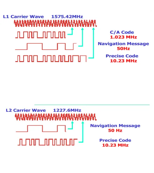
•The SVs transmit two microwave carrier signals. The L1 frequency (1575.42 MHz) carries the navigation message and the SPS code signals. The L2 frequency (1227.60 MHz) is used to measure the ionospheric delay by PPS equipped receivers.
•Three binary codes shift the L1 and/or L2 carrier phase.
•The C/A Code (Coarse Acquisition) modulates the L1 carrier phase. The C/A code is a repeating 1 MHz Pseudo Random Noise (PRN) Code. This noise-like code modulates the L1 carrier signal, "spreading" the spectrum over a 1 MHz bandwidth. The C/A code repeats every 1023 bits (one millisecond). There is a different C/A code PRN for each SV. GPS satellites are often identified by their PRN number, the unique identifier for each pseudo-random-NOISE code. The C/A code that modulates the L1 carrier is the basis for the civil SPS.
•The P-Code (Precise) modulates both the L1 and L2 carrier phases. The P-Code is a very long (seven days) 10 MHz PRN code. In the Anti-Spoofing (AS) mode of operation, the P-Code is encrypted into the Y-Code. The encrypted Y-Code requires a classified AS Module for each receiver channel and is for use only by authorized users with cryptographic keys. The P (Y)-Code is the basis for the PPS.
Message is a 50 Hz signal consisting of data bits that describe the GPS satellite orbits, clock corrections, and other system parameters. [K.EREN, 2003
L1 Carrier Wave 1575.42MHz C/A Code 1.023 MHz Navigation Message 50Hz Precise Code 10.23 MHz L2 Carrier Wave 1227.6MHz Navigation Message 50 Hz Precise Code 10.23 MHz
Figure 2.3- GPS Signal Structure[NIMA
2.4.1 Position, and Time from GPS
Since GPS is based on knowing your distance to satellites in orbit, a method must be devised to figure out how far we are from the satellites. The GPS system works by timing how long it takes a radio signal to reach us from a satellite and then calculating the
distance from that time. We calculate this by measuring distance or the velocity times travel time. Radio waves travel at the speed of light: 186,000 miles per second.
If we can then compute the exactly when the signal started at the satellite and ended at the receiver then we have our required distance. We then multiply the time by the velocity to derive the distance.
The time is differential is computed by synchronizing the satellites and receivers so they are generating the same code at exactly the same time
Figure (2.4) is a diagram that shows how radio signals work in general. Each SV generates a plain sine wave called the Carrier 1575.42 MHz and 1227.6 MHz. This carrier is modulated (altered) by adding three signals to it. (The C/A code, P-Code and the Navigation message). In this case, it is that particular SV's Pseudo-Random Noise (PRN) Code this is essentially the P-Code and the C/A code for each SV. The PRN code looks like a square wave because it's just 1's and 0's; digital information that is Phase Modulated (PM).
Then what the SV actually broadcasts is that modulated signal. Your receiver picks this up, subtracts the carrier (it can generate a copy of the carrier on its own), and is left with a copy of the original signal. All radios works this way. The significance for GPS is that the signal that is produced in the receiver is delayed by a small amount of time. For GPS, the information in the signal is not the only important part - as we've seen, it's the time delay that we really care about. In fact, GPS receivers already have to have a copy of the signal (most of it anyway) just to pick it up in the first place. Remember, all the SVs are talking on the same frequency, so we can't pick them out of the chatter without knowing what to expect ahead of time.
Transmission Time Receiver Time delay The Carrier... combined with The PRN code... produces the
Modulated carrier signal which is transmitted... demodulated...
Producing the same code at the user, but delayed...
Satellite
Figure 2.4 - Radio signals [NIMA]
2.4.1.1 Receiver Position is based on Time
The Global Positioning System allows a GPS receiver to determine its position by using a simple formula: Velocity x Time = Distance
GPS satellites continuously transmit digital radio pulses at precise, known times. So by measuring the exact instant when the pulses arrive, the receiving GPS equipment can determine the distance to each satellite. But there’s a problem. The clocks on board the satellites are all extremely accurate, while the clock in the GPS receiver is not. So a GPS receiver calculates what are called pseudo-ranges (“false” ranges), which are approximate calculated distances (as a measurement of time) to every satellite the receiver has acquired.
Eventually, in order for the GPS receiver to determine a precise position it will have to get its own clock synchronized with the satellite clocks. A clock error in the GPS receiver of as little as a few nanoseconds (billionths of a second) can translate into a position error on the ground of as much as 300 meters. (More about this later.)
For example, if a GPS satellite transmits its signal at precisely T+ 0 nanoseconds, travels at 186,000 miles per second (light speed) to the earth, and arrives at the receiver at precisely T+ 645,160 nanoseconds later, then the signal traveled 12,000 miles (12,000 miles at 186,000 miles per second = 64.516 milliseconds, or 645,160
nanoseconds). The receiver does this for every satellite signal it acquires, tracking each satellite’s code by its unique pseudo random noise (PRN) number. This example was presented without introducing any errors into the signal or its path to the GPS receiver. More about that later. [Charlie Leonard 1999.]
2.4.1.2 How the Current Locations of GPS Satellites are Determined
GPS satellites are orbiting the Earth at an altitude of 11,000 miles. The DOD can predict the paths of the satellites vs. time with great accuracy. Furthermore, the satellites can be periodically adjusted by huge land-based radar systems. Therefore, the orbits, and thus the locations of the satellites, are known in advance. Today's GPS receivers store this orbit information for all of the GPS satellites in what is known as an almanac. Think of the almanac as a "bus schedule" advising you of where each satellite will be at a particular time. Each GPS satellite continually broadcasts the almanac. Your GPS receiver will automatically collect this information and store it for future reference.
The Department of Defense constantly monitors the orbit of the satellites looking for deviations from predicted values. Any deviations (caused by natural atmospheric phenomenon such as gravity), are known as ephemeris errors. When ephemeris errors are determined to exist for a satellite, the errors are sent back up to that satellite, which in turn broadcasts the errors as part of the standard message, supplying this information to the GPS receivers. By using the information from the almanac in conjunction with the ephemeris error data, the position of a GPS satellite can be very precisely determined for a given time.
2.4.1.3 How A GPS Receiver Determines Its Position
Each satellite transmits what’s called a Navigation Message, which is downloaded by GPS receivers. The NAV Message the following information: GPS constellation status (all the satellites) satellite ephemeris and health data (individual satellites), GPS Time and UTC time transfer parameters, and ionosphere interference correction parameters. The GPS currently uses two frequencies to accomplish data transmission, L1 and L2. The NAV Message and coarse acquisition information are provided on the L1 frequency.
position and navigation precision of GPS receivers.
Receiver PRN
Satellite PRN Time
Difference
Figure 2.5- The pseudo random noise (PRN) code [Charlie Leonard 1999.]
The pseudo random noise (PRN) code is a fundamental part of the GPS. It's a very complicated digital code unique to each satellite. It’s a complex sequence of "on" and "off” digital pulses (see the diagram). The signal looks like random electrical noise (similar to the “snow” you might see on a TV), but is actually a very precise code. Hence the name “pseudo-random noise.”
When a GPS receiver acquires a GPS signal it examines the satellite’s incoming PRN and begins generating a matching digital signal to mimic the satellite’s signal. The receiver matches each satellite’s PRN code with an identical copy of the code contained in the receiver’s database. Its next task is to try and determine how long ago the signal was generated by the satellite. But there’s a problem. As explained earlier, each satellite is equipped with atomic clocks; clocks which are constantly monitored for accuracy by the Master Control Station. The GPS receiver on the other hand is equipped only with a single digital clock comparable to a cheap wrist watch. The only way for the receiver to calculate an accurate position is if it can accurately measure the precise travel time of the satellite radio signal. A discrepancy of just a few nanoseconds between satellite and receiver will translate into a large position error on the ground.
So the GPS receiver uses a clever technique to calculate the precise time it took for the GPS signal to reach it. By shifting its own generated copy of the satellite’s PRN code in a matching process, and by comparing this shift with its own internal clock,
the receiver can calculate how long it took the signal to travel from the satellite to itself. By comparing the time difference between the two, and multiplying that time by the 186,000 miles per second travel speed of the signal, the receiver can roughly determine the distance separating it from the satellite. This process is repeated with every satellite signal the receiver locks on to.
The distance between satellite and receiver derived from this method of computing distance is called a pseudo-range (“false range”) because the receiver’s clock is not synchronized with the satellites clocks. Pseudo-range is subject to several error sources, such as delays caused by the atmosphere, and multipath interference. More about that later.
Here’s a simplified example of how a GPS receiver synchronizes itself to GPS Time for precise positioning. Imagine that the GPS satellite PRN signal is a song being broadcast by a radio station. The GPS receiver is a record player which is playing the same song, but it’s not synchronized to the broadcast song. Both songs are playing, but at different places in the song and at different speeds. By speeding up or slowing down the turntable, the two songs can be precisely matched. They become synchronized. Similarly, the GPS receiver synchronizes its digital signal to match that of each satellite’s signal.
Once the receiver has its internally generated PRN code in synch with the satellite’s code it can determine a pseudo-range distance to the satellite. It does this for every satellite signal it receives. As will be explained later, under ideal conditions four satellites are used to calculate a precise position.
Since GPS Time is one of the most important components of the System, it’s important to understand what GPS Time actually is. GPS Time is measured in weeks and seconds from 24:00:00, January 5, 1980 and is adjusted to within one microsecond of Universal Coordinated Time (UTC). Universal Coordinated Time is the international standard for time, and is tied to the earth’s rotation. Because of this it must be periodically adjusted to compensate for the slowing of the earth’s rotation – these adjustments are called leap seconds. But because GPS Time has no leap seconds, it is not adjusted, which puts it ahead of UTC time by several seconds. Universal Coordinated Time is computed from GPS Time using the UTC correction parameters sent by the Master Control Station to the satellite constellation as part of the navigation message. At
1997, UTC time was retarded one additional second, putting GPS Time ahead of UTC time by thirteen seconds. A GPS receiver will use the GPS Time to UTC time correction parameter to provide the user with UTC time on the receiver’s display.
It’s important to note that setting an incorrect time zone in a GPS receiver has no effect on the receiver’s ability to provide an accurate position. An incorrect time zone merely provides different time on a receiver’s display, not inaccurate time.
2.4.1.4 Time from GPS
Universal Time Coordinated (UTC) is the same as Greenwich Mean Time (GMT), which runs through Greenwich, England - hence its name. It’s also known as “Zulu” time (a term used mostly by pilots and the military). Greenwich, England is where east meets west for both time zones and latitude and longitude coordinates. The world is broken down into 24 time zones of one hour each. Universal Time Coordinated is the “official” time standard recognized by most of the world, and it forms the basis for GMT and Zulu time.
Midnight in Greenwich, England is 0000 hours UTC and Zulu (and 0000 hours + 13 seconds in GPS Time!). Each time zone east of Greenwich adds one hour, and each time zone west of Greenwich subtracts an hour. Most of the United States practices Daylight Saving Time (DST) during spring and summer, which adds one hour to each U.S. time zone. The rest of the year is referred to as Standard Time. When it’s midnight in Greenwich, it’s five hours (or five time zones) behind on the eastern seaboard of the U.S. during Standard Time (7:00 PM), or four hours (or four time zones) behind Greenwich during Daylight Saving Time (8:00 PM).
Universal Time Coordinated is not military time. Military time is simply using a 24 hour clock to represent local time. For example, 1800 hours in military time is 6:00 p.m. local time. But 1800 hours Zulu time (or UTC time, or Greenwich Time) is 6:00 p.m. in Greenwich, England.
Presented another way, 1800 hours in military time in Boise, Idaho (6:00 p.m. local) is 2400 hours in UTC time during Mountain Daylight Saving Time, or 0100 hours during Mountain Standard Time (Boise lies in the seventh time zone behind Greenwich). But if it’s 9:00 AM (0900 military time) in Boise, and you tell someone that you will
meet them at a pub at 1600 Zulu (assuming Standard Time), then you had better hurry because 0900 Mountain Standard Time is 1600 Zulu Time!
Some points to remember about time:
UTC, GMT and Zulu time are all the same, and refer to local official time set in Greenwich, England. All other time zones must add or subtract hours to convert UTC, GMT and Zulu to local time.
Military time is nothing more than local time converted to a 24 hour clock (2:00 p.m. is 1400 hours, and so on).
UTC time is the “official” time for the entire world, and is kept by a number of observatories around the world (the U.S. Naval Observatory is one – http://tycho.usno.navy.mil).
The Global Positioning System operates on GPS Time, which is UTC time plus approximately 13 seconds (periodic adjustments in leap seconds may vary the number of seconds).
The following chart shows different time offsets for various cities. All times shown assume Standard Time, but the last column provides Daylight Saving Time (DST) conversion for that city. Remember, Daylight Saving Time occurs only in spring and summer, and most of the world does not subscribe to it.
Place Local Time Military (local)
UTC, GMT,
Zulu Time Zone Local DST Offset Greenwich, UK 12:00p.m 1200 hours 0000 hours 0 offset 0
Tallahassee, FL 7:00 p.m 1900 hours 0000 hours - 5 hours -4 hours (8:00 p.m.)
Tallahassee, FL 11:00 a.m 1100 hours 1600 hours -5 hours -4 hours (12:00 p.m.)
Joshua Tree, CA 2:00 a.m 0200 hours 1000 hours -8 hours -7 hours (03:00 a.m.) Joshua Tree, CA 10:30 p.m. 2230 hours 0630 hours* -8 hours -7 hours (03:00 a.m.)
Paris, FR** 4:00 p.m. 1600 hours 1500 hours +1 hour
Table 2.1- different time offsets for various cities [Charlie Leonard 1999.]
* 0630 (or 6:30 a.m.) the next day.
** Paris lies east of Greenwich by one hour, so time is added rather than subtracted. But DST is not affected.
Note: all GPS receivers perform position calculations using GPS Time. But the time shown on a receiver’s screen is UTC time (currently 13 seconds behind GPS Time). According to the Garmin Company, their receiver clocks usually vary from ½ to 1 second from true UTC time if a current almanac is loaded in the receiver.
2.5 GPS SURVEY TECHNIQUES 2.5.1 Pseudo Range Navigation
The position of the receiver is where the pseudo-ranges from a set of SVs intersect.
Position is determined from multiple pseudo-range measurements at a single measurement epoch. The pseudo range measurements are used together with SV position estimates based on the precise orbital elements (the ephemeris data) sent by each SV. This orbital data allows the receiver to compute the SV positions in three dimensions at the instant that they sent their respective signals.
Four satellites (normal navigation) can be used to determine three position dimensions and time. Position dimensions are computed by the receiver in Earth-Centered, Earth-Fixed X, Y, Z (ECEF XYZ) coordinates.
Time is used to correct the offset in the receiver clock, allowing the use of an inexpensive receiver clock.
SV Position in XYZ is computed from four SV pseudo-ranges and the clock correction and ephemeris data.
Receiver position is computed from the SV positions, the measured pseudo-ranges (corrected for SV clock offsets, ionospheric delays, and relativistic effects), and a receiver position estimate (usually the last computed receiver position).
Three satellites could be used determine three position dimensions with a perfect receiver clock. In practice this is rarely possible and three SVs are used to compute a two-dimensional, horizontal fix (in latitude and longitude) given an assumed height. This is often possible at sea or in altimeter equipped aircraft. Five or more satellites can provide position, time and redundancy. More SVs can
provide extra position fix certainty and can allow detection of out-of-tolerance signals under certain circumstances. [K.EREN,2003]
2.5.2 Carrier Phase Tracking (Surveying)
Carrier-phase tracking of GPS signals has resulted in a revolution in land surveying. A line of sight along the ground is no longer necessary for precise positioning. Positions can be measured up to 30 km from reference point without intermediate points. This use of GPS requires specially equipped carrier tracking receivers.
The L1 and/or L2 carrier signals are used in carrier phase surveying. L1 carrier cycles have a wavelength of 19 centimeters. If tracked and measured these carrier signals can provide ranging measurements with relative accuracies of millimeters under special circumstances.
Tracking carrier phase signals provides no time of transmission information. The carrier signals, while modulated with time tagged binary codes; carry no time-tags that distinguish one cycle from another. The measurements used in carrier phase tracking are differences in carrier phase cycles and fractions of cycles over time. At least two receivers track carrier signals at the same time. Ionospheric delay differences at the two receivers must be small enough to insure that carrier phase cycles are properly accounted for. This usually requires that the two receivers be within about 30 km of each other.
Carrier phase is tracked at both receivers and the changes in tracked phase are recorded over time in both receivers.
All carrier-phase tracking is differential, requiring both a reference and remote receiver tracking carrier phases at the same time.
Unless the reference and remote receivers use L1-L2 differences to measure the ionospheric delay, they must be close enough to insure that the ionospheric delay difference is less than a carrier wavelength.
Using L1-L2 ionospheric measurements and long measurement averaging periods, relative positions of fixed sites can be determined over baselines of hundreds of kilometers.
Phase difference changes in the two receivers are reduced using software to differences in three position dimensions between the reference station and the remote receiver. High accuracy range difference measurements with sub-centimeter accuracy are possible. Problems result from the difficulty of tracking carrier signals in noise or while the receiver moves.
Two receivers and one SV over time result in single differences. Two receivers and two SVs over time provide double differences.
Post processed static carrier-phase surveying can provide 1-5 cm relative positioning within 30 km of the reference receiver with measurement time of 15 minutes for short baselines (10 km) and one hour for long baselines (30 km). Rapid static or fast static surveying can provide 4-10 cm accuracies with 1
kilometer baselines and 15 minutes of recording time.
Real-Time-Kinematic (RTK) surveying techniques can provide centimeter measurements in real time over 10 km baselines tracking five or more satellites and real-time radio links between the reference and remote receivers. [K.EREN,2003]
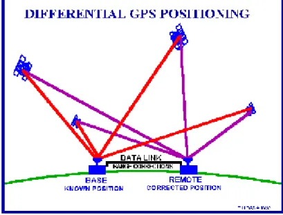
2.5.3 Differential GPS (DGPS) Techniques (General principals)
The idea behind all differential positioning is to correct bias errors at one location with measured bias errors at a known position. A reference receiver, or base station, computes corrections for each satellite signal.
Because individual pseudo-ranges must be corrected prior to the formation of a navigation solution, DGPS implementations require software in the reference receiver that can track all SVs in view and form individual pseudo-range corrections for each SV. These corrections are passed to the remote, or rover, receiver which must be capable of applying these individual pseudo-range corrections to each SV used in the navigation solution. Applying a simple position correction from the reference receiver to the remote receiver has limited effect at useful ranges because both receivers would have to be using the same set of SVs in their navigation solutions and have identical GDOP terms (not possible at different locations) to be identically affected by bias errors. . [K.EREN,2003]
2.5.3.1 Differential Code GPS (Navigation)
Differential corrections may be used in real-time or later, with post-processing techniques.
Real-time corrections can be transmitted by radio link. The U. S. Coast Guard maintains a network of differential monitors and transmits DGPS corrections over radio beacons covering much of the U. S. coastline. DGPS corrections are often transmitted in a standard format specified by the Radio Technical Commission Marine (RTCM).
Corrections can be recorded for post processing. Many public and private agencies record DGPS corrections for distribution by electronic means.
Private DGPS services use leased FM sub-carrier broadcasts, satellite links, or private radio-beacons for real-time applications.
To remove Selective Availability (and other bias errors), differential corrections should be computed at the reference station and applied at the remote receiver at an update rate that is less than the correlation time of SA. Suggested DGPS update rates are usually less than twenty seconds.
DGPS removes common-mode errors, those errors common to both the reference and remote receivers (not multipath or receiver noise). Errors are more often common when receivers are close together (less than 100 km). Differential position accuracies of 1-10 meters are possible with DGPS based on C/A code SPS signals. . [K.EREN,2003]
2.5.3.2 Differential Carrier GPS (Survey)
All carrier-phase tracking is differential, requiring both a reference and remote receiver tracking carrier phases at the same time.
In order to correctly estimate the number of carrier wavelengths at the reference and remote receivers, they must be close enough to insure that the ionospheric delay difference is less than a carrier wavelength. This usually means that carrier-phase GPS measurements must be taken with a remote and reference station within about 30 kilometers of each other.
Special software is required to process carrier-phase differential measurements. Newer techniques such as Real-Time-Kinematic (RTK) processing allow for centimeter relative positioning with a moving remote receiver. . [K.EREN,2003]
Figure 2.6- Differential GPS Positioning
2.6 Trilateration, How GPS Determines a Location
For simplicity sake, we calculate our position by understanding where a satellite is in orbit and then further computing how far we are from those satellites.
2.6.1 Signals from One Satellite
Signal From One Satellite
Signal From One Satellite
The receiver is somewhere on this sphere.
Figure 2.8 Signals From One Satellite [Charlie Leonard 1999.]
GPS receiver to accurately calculate the distance between it and each satellite provided that several factors are met.
Those factors are:
Good satellite signal lock by the GPS receiver (already covered) A minimum of four satellite signals (discussed next)
Good satellite geometry (discussed later)
When a GPS receiver is turned on it immediately begins searching the sky for satellite signals. If the receiver already has a current almanac (such as one acquired on a previous outing), it speeds up the process of locating the first satellite signal. Eventually it locates and acquires its first signal. Reading this signal the receiver collects the Navigation Message. If the receiver does not have a current almanac, or was moved
about 12-13 minutes after the first satellite signal is acquired. Why the need for a new almanac if the receiver is moved more than 300 miles while turned off? Beyond 300 miles from its last used location the receiver is presumed to be using different GPS satellites, and therefore should download a new almanac to reflect the new PRN codes. If the receiver is turned on and collecting satellite signals while moving over 300 miles, its almanac is automatically updated.
In the above graphic, the GPS receiver calculates a rough location somewhere on this three dimensional sphere, which is actually thousands of miles in diameter. All the receiver can really do at this point is collecting system data and search for more satellites. [Charlie Leonard 1999.]
2.6.2 Signals from Two Satellites
Signals From Two Satellites
Signals From Two Satellites
Figure 2.9 Signals From Two Satellite [Charlie Leonard 1999.]
In a perfect world, where both satellite and receiver clocks were perfectly synchronized with each other, an accurate position could be determined from just two satellites. However, most receivers are incapable of calculating an accurate position using just two satellites. The dot in the example represents the approximate location of where the receiver thinks it is based on the information provided by two satellites. At least now the
receiver knows that it is somewhere at the intersection of those two satellite signals. But that’s the only improvement in its position calculations.
The satellite signal spheres should intersect at precisely the receiver’s location, but don’t because the clock in the GPS receiver isn’t yet synchronized with GPS Time. So the receiver estimates a “pseudo-range” to each satellite.
2.6.3 Three Satellites (2D Positioning)
Three Satellites (2D Positioning)
Three Satellites (2D Positioning)
Figure 2.10- 2D Positioning [Charlie Leonard 1999.]
Three satellites can provide only a two-dimensional (2D) position. Without manually entering the receiver’s exact elevation (most GPS receivers don’t allow elevation to be entered manually), the rendered 2D position may be off by several kilometers on the ground. If the exact elevation of the GPS receiver is known, entering that elevation into a receiver with this capability replaces the need for a fourth satellite signal to allow a receiver to triangulate a precise position. The receiver essentially uses elevation in lieu of a fourth satellite, and makes the appropriate adjustments to trilaterate a reasonably good 3D position.
But without manual elevation correction most GPS receivers must rely on a fourth satellite to provide the final clock correction information necessary to calculate a 3D position. Until a fourth satellite signal is acquired the receiver will not be able to determine x and y horizontal, and z vertical positioning (a true 3D position). This is
data, but, rather, the final time correction factor in its ranging calculations.
As a rule, 2D positions should always be avoided whenever possible. Use 2D positioning only when a 3D position is not possible, but be aware of the horizontal error inherent in any 2D position. The inability of a GPS receiver to triangulate a 3D position may be due to a variety of factors, including user error, poor satellite geometry, and harsh landscape conditions (tall buildings, canyons, and dense tree cover among others). As will be shown later in the course, all GPS receivers provide some means for informing the user which mode they are operating in. It’s up to the user to be aware of the errors associated with 2D positioning.
2.6.4 Triangulating Correct Position
Unfortunately, accessing only two or three satellite signals, the clock in the GPS receiver cannot yet be synchronized precisely with GPS Time. The pseudo-range spheres (the diagram here shows only two satellites for simplification), as interpreted by the GPS receiver, will either be just a little too large (if the receiver’s clock is running faster than GPS Time) or too small (if the receiver’s clock is slower than GPS Time). The spheres will not intersect with each other. In this example, the “do not” could be the false pseudo-range position if the GPS receiver’s clock is running faster than GPS Time, or the dot is the position if the receiver’s clock is slower than GPS Time. For the purpose of this example, we’ll pretend that the receiver’s clock is running a little fast, so the dot is the true location.
Triangulating Correct Position
Triangulating Correct Position
Figure 2.11- Triangulating Correct Position [Charlie Leonard 1999.]
2.6.5 Three Dimensional (3D) Positioning
For a GPS receiver to achieve three-dimensional (3D) positioning it needs to acquire four or more satellite signals. A 3D position is comprised of X and Y (horizontal), Z (vertical) positions, and precise time (not varying more than a few hundred nanoseconds). The receiver’s processor uses the fourth satellite pseudo-range as a timing cross check to estimate the discrepancy in its own ranging measurements and calculate the amount of time offset needed to bring its own clock in line with GPS Time (recall the radio station and record player simultaneously playing the same song). Since any offset from GPS Time will affect all its measurements, the receiver uses a few simple algebraic calculations to come up with a single correction factor that it can add or subtract from all its timing measurements that will cause all the satellite spheres to intersect at a single point (x, y, and z).
Figure 2.12- 3D Positioning [Charlie Leonard 1999.]
That time correction synchronizes the receiver's clock with GPS Time. Now the receiver essentially has atomic clock accuracy with the time correction factor needed to achieve precise 3D positioning. The pseudo-ranges calculated by the GPS receiver will correspond to the four pseudo-range spheres surrounding the satellites, causing the four spheres to intersect at precisely the receiver’s location (the dot in the diagram).
2.7 The GPS Error Budget
The GPS system has been designed to be as nearly accurate as possible. However, there are still errors. Added together, these errors can cause a deviation of +/- 50 -100 meters from the actual GPS receiver position. There is a host of errors that are inherent with a GPS system. The accuracy of a GPS is influenced by this budget. Collectively these factors combine to induce the 100m plan position error, at 2 deviations root mean square (2drms) at 98% probability experienced by Standard Positioning System (SPS) users, and 17.8m at 2 deviations root mean square (2drms) at 98% probability experienced by the Precise Positioning System (PPS) users. The sum of all the errors or biases is referred to as bias range or “pseudo range.”
Principal contributors to the final range error that also contribute to the overall GPS error are ephemeris error, satellite clock error, electronic inaccuracies, tropospheric and ionospheric refraction, atmospheric absorption, receiver noise and multipath effects. In addition to these errors, GPS also contains other interruptions to the service that can be introduced by the U.S. DoD are Selective Availability and Anti-Spoofing.
2.7.1 Sources of GPS Error
GPS errors are a combination of noise, bias, and blunders.
Noise errors are the combined effect of PRN code noise (around 1 meter) and noise within the receiver noise (around 1 meter).
Bias errors result from Selective Availability and other factors: SV clock errors, Ephemeris data errors, unordered ionosphere delays, Multipath.
Blunders can result in errors of hundred of kilometers from: Control segment mistakes, User mistakes, Receiver errors.
2.7.1.1 Selective Availability (S / A)
Selective Availability (S/A) was the intentional degradation (referred to as “dithering”) of the Standard Positioning Service (SPS) signals by a time varying bias. Selective Availability is controlled by the DOD to limit accuracy for non-U. S. military and government users. The potential accuracy of the coarse acquisition (C/A) code at
![Figure 2.1- Monitor and control stations [NIMA]](https://thumb-eu.123doks.com/thumbv2/9libnet/3505485.16784/18.892.172.785.512.960/figure-monitor-and-control-stations-nima.webp)
![Table 2.1- different time offsets for various cities [Charlie Leonard 1999.]](https://thumb-eu.123doks.com/thumbv2/9libnet/3505485.16784/31.892.115.779.217.590/table-different-time-offsets-various-cities-charlie-leonard.webp)
![Figure 2.8 Signals From One Satellite [Charlie Leonard 1999.]](https://thumb-eu.123doks.com/thumbv2/9libnet/3505485.16784/38.892.274.688.412.704/figure-signals-from-one-satellite-charlie-leonard.webp)
![Figure 2.9 Signals From Two Satellite [Charlie Leonard 1999.]](https://thumb-eu.123doks.com/thumbv2/9libnet/3505485.16784/39.892.285.657.603.827/figure-signals-from-two-satellite-charlie-leonard.webp)
![Figure 2.10- 2D Positioning [Charlie Leonard 1999.]](https://thumb-eu.123doks.com/thumbv2/9libnet/3505485.16784/40.892.285.654.423.649/figure-d-positioning-charlie-leonard.webp)
![Figure 2.11- Triangulating Correct Position [Charlie Leonard 1999.]](https://thumb-eu.123doks.com/thumbv2/9libnet/3505485.16784/42.892.288.687.227.479/figure-triangulating-correct-position-charlie-leonard.webp)
![Figure 2.13- GPS Multipath Errors [Fred T. Henstridge 1999]](https://thumb-eu.123doks.com/thumbv2/9libnet/3505485.16784/47.892.270.695.416.629/figure-gps-multipath-errors-fred-t-henstridge.webp)
