Full Terms & Conditions of access and use can be found at
https://www.tandfonline.com/action/journalInformation?journalCode=nsme20
International Journal of Mining, Reclamation and
Environment
ISSN: 1748-0930 (Print) 1748-0949 (Online) Journal homepage: https://www.tandfonline.com/loi/nsme20
A pick force calculation method suggested for tool
lacing of mechanical excavators employing drag
tools
Osman Zeki Hekimoglu
To cite this article: Osman Zeki Hekimoglu (2018) A pick force calculation method suggested for tool lacing of mechanical excavators employing drag tools, International Journal of Mining, Reclamation and Environment, 32:8, 564-585, DOI: 10.1080/17480930.2017.1317946 To link to this article: https://doi.org/10.1080/17480930.2017.1317946
Published online: 20 Apr 2017.
Submit your article to this journal
Article views: 211
View related articles
View Crossmark data
Citing articles: 3 View citing articles
.'.ll.•; ... .,, .. , MINING, RECLAMATION AND ENVIRONMENT ~~
1.111
11
CrossMdrke2]
13' 13' 13' 13'https://doi.org/10.1080/17480930.2017.1317946
A pick force calculation method suggested for tool lacing of
mechanical excavators employing drag tools
Osman Zeki Hekimoglu
faculty of engineering, department of Mining engineering, Mugla Sitki Kocman university, Mugla, turkey
ABSTRACT
This paper deals with tool lacing design of partial-face cutting machines employed for mechanical excavations of rocks, coal and stones. A rational comparison between relief cutting and groove deepening was made by simulating actual cutting actions of picks under the same conditions at different spacing to depth ratios, respectively, through full-scale laboratory linear cutting experiments with radial and point attack tools. It was found that the top portion of a groove with approximately polygonal-shaped cross section has no significant effect on the magnitude of tool forces. The effective cutting was understood to take place mainly in the lower portion of this cross section, termed ‘effective area’, which is encompassed by a triangle with an apex angle twice the breakout angle of unrelieved groove. This finding has led to the introduction of a pick force calculation method for computer assessment of tool lacing for rock, coal and stone cutting machines. The ‘effective area’ of cross sections which were calculated by this method, was found to be in good correlation with corresponding measured tool forces. The method is simple and free from assumptions which have to be specified for various pick cutting position. It was also verified by the results of some experimental data of previous investigations.
1. Introduction
In mechanical excavation, roadheaders, continuous miners and coal shearers, are widely employed for underground mining and tunnelling, while chain saw machines are employed for production of natural stones in quarry mining. Point attack type cutter picks, among all drag tools, are predominantly employed by roadheaders and drum shearers for excavations of rocks and coal. Radial tools are no longer common in underground mining and tunnelling today, whereas they are extensively employed for chain saw machines in quarry mining.
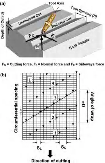
Arrangement of cutter picks on a given cutting unit of above-mentioned machines, known as tool lacing, is one of the important factors affecting machine performance. Tool spacing, circumferential spacing, number of tracking cutters, angle of wrap and tilt angle are the fundamental design parame-ters in tool lacing. Some of them relevant to the scope of this paper are shown in Figure 1. The lateral distance between the immediate neighbouring tools along the axis perpendicular to the direction of cutting is known as ‘line spacing (SL)’, while that between the tools of the same sequence is termed
© 2017 Informa uK limited, trading as taylor & francis group
KEYWORDS
cutting head design; roadheaders; drum shearers; natural stones; mechanical excavation
ARTICLE HISTORY
received 5 april 2017 accepted 7 april 2017
CONTACT osman Zeki Hekimoglu [email protected]
InternatIonal Journal of MInIng, reclaMatIon and envIronMent
2018, Vol. 32, No. 8, 564–585
C\
~ Taylor&
FrancisTaylor&FrancisGroup
‘cut spacing (SC)’. The angular distance between the successive tools along the axis in-line with the direction of cutting is called ‘circumferential spacing’. The angular extent of a spiral line measured along drum circumference is known as ‘angle of wrap’.
Laboratory linear cutting trials on flat rock surface showed that a minimum specific energy occurs when the line spacing are set to a certain value at a given depth of cut which is called optimum spacing to depth ratio (s/d). The limit of interaction between adjacent grooves was reported to occur at ‘2 tan
θ’, where θ is half breakout angle of the groove which generally varies between 52° and 70° depending
upon rock properties [1–3].
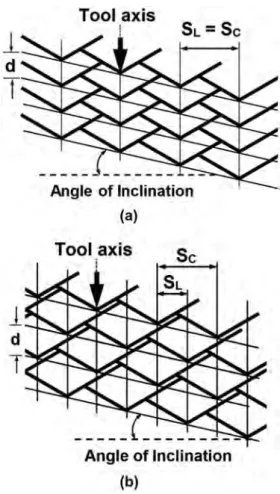
A pick is said to perform a ‘relief cutting’ when it hits the midway between the tools of a preced-ing sequence, whereas the cuttpreced-ing mode is called ‘groove deepenpreced-ing’ if the picks in a given sequence exactly follow the same lines or the tracks of the tools of preceding sequence (Figure 2). With groove deepening, the line spacing equals cut spacing, while with relief cutting, the cut spacing is always a multiple of line spacing.
Early studies emphasised that the groove deepening should be avoided, since it is inefficient [3,4]. These findings were, however, based upon the results of laboratory trials carried out on a flat rock surface and their results are not necessarily applicable to the case of tools on an actual cutting head or a drum which cut into a surface formed by preceding cutting sequences. The action of a roadheader
Figure 1. Some fundamental parameters considered (a) in laboratory linear cutting experiments and (b) in tool lacing with the vane picks of a practical shearer drum having four starts with 2 tools per line.
Fe :: Cutting force, Fn = Normal force and Fs :: Sideways force (b) - 1 4 "' 3 ,_ :ct
I
CI
-
2 1--
,~
-l
I-Sc'
Direction of cuttingwas simulated in relief cutting mode with point attack tools, using a medium strength limestone [5]. The specific energy was reported to decrease with spacing to depth of cut ratio (s/d) rapidly at first and then more slowly, while tool forces increase continually (Figure 3). Lower specific energy contin-ues beyond the point of interaction between the adjacent grooves, at the expense of high tool forces, as opposed to the previous laboratory investigations on flat rock surface. A balance was, therefore, noted to be reached between optimum cutting efficiency and acceptable level of tool forces, thus, the tool life, not cutting efficiency, was suggested to be the primary selection criterion. A laboratory linear cutting investigations on simulating a cycloidal action of a drum shearer at a fixed tool spacing for groove deepening and relief cutting, respectively, showed that, with groove deepening, the tool forces were initially high and then gradually attained the same value of relief cutting at higher cutting depths (Figure 4) [6]. Underground investigations on coal shearers demonstrated significant increase in overall machine performance, when groove deepening lacing was modified to relief cutting [6]. The cutting rate was reported to increase while tool wear was minimised when the tool lacing of a chain saw machine which was designed in groove deepening was partially modified to relief cutting, and the fundamental procedures for tool lacing of roadheaders cutting head were noted to be very similar to that of chain saw machines [7]. Chain saw machines operating in practice were reported to adopt groove deepening concept, and relief cutting was suggested for these machines [8]. The profile shape of grooves deepened by successive cuts of picks arranged in groove deepening mode was investigated through laboratory linear cutting experiments [9]. The cutting was reported to be successful and breakout angles were consistent with optimum s/d value. However, pick damage was
Figure 2. Breakout pattern of successive picks (a) in groove deepening and (b) in relief cutting.
566 O. Z. HEKIMOGLU
Tool axis
1SL= Sc
Angle of Inclination (a)Tool axis
Angle of Inclination (b)observed and, breakout angles were drastically decreased after the first pass, at an excessive tool spacing. Despite the advantages of relief cutting, the groove deepening mode has, however, been still persistently employed in practice with many rock, coal and stone cutting machines, probably due to a lack of conclusive investigations. The author of this paper has found no investigations in published literature, on simulating the practical actions of these two cutting modes for a rational comparison. Such an investigation is believed to fill an important gap in this subject.
The importance of tool lacing has increased developments in computer-aided design of cutting heads and cutting drums. A computer software was introduced at British Coal in UK [10,11]. It was stated that the relative duty required of each tool should be estimated by examining the relation of each cut to its predecessors. This can be achieved by constructing a ‘cutting (breakout) pattern’ which is the arrangement of cross sections of cuts formed by combining the cutting sequences with the spatial position of each tool tip during cutting, as shown in Figure 5. Any conflicting design requirement
Figure 3. effect of cut depth and spacing on (a) mean cutting force and (b) specific energy [5]. 24
z
20
.:.::-
QIf
16 0u.
a, 12 CE
:i 8 0 C:3
4==
Cul Spacing (mm) Depth of Cut (mm) 20 0 .,__--r--- ~ -..---..--~.---. 0 J 2 3 4 5 6Spacing to Depth Ratio
(a)
I'.! Depth ;;- (mm) 10E
-
-,
~-
>, 8e>
Q) 6 C:w
u
4!E
u
8.
2 Ul Cut Spacing (mm)(I~-~
-
- -
-
- - - - ~
u 2 3 4 5 6Spacing to Depth Ratio
can be detected and then resolved through the breakout patterns. The cutting force component was reported to be proportional to the cross-sectional area swept by a tool on the breakout pattern, pro-vided that the cut is relieved, and force magnitudes were calculated by empirical equations related to these cross-sectional areas [12]. Successful machine performances were reported through the use this software [13]. A computer programme was also reported for performance assessment of roadheaders cutting heads, however no information was available on tool force calculation considered with this software [14]. Further researches on designing roadheaders cutting heads and shearer drums with the aid of computer were carried out predominantly in China, and to a certain extent, in Europe and South Korea, especially after 2000 [15–27]. However, with none of these studies the tool forces were seen to be calculated from cross-sectional areas swept by tools.
Considering the whole area of cross sections alone is obviously not a realistic approach for tool force calculation method, since different tool forces are inevitable when the same cross sections are cut at different tool positions. Laboratory linear cutting research with roadheaders cutting head where cutting order of picks was compared in terms of starting from machine side to face or vice versa, showed that tool forces varied with relative tool positions, despite the fact that the picks were cutting the same cross sections, respectively, under equal conditions [28]. Furthermore, very similar finding was also reported when different angle of wraps at a fixed s/d value were compared through linear cutting experiments for a given cutting drum [29]. The pick cutting positions, therefore, have to be
Figure 4. variation of mean cutting force with depth of cut at constant spacing [6].
Figure 5. a breakout pattern of the picks on an axial-type roadheaders cutting head.
568 O. Z. HEKIMOGLU
4 6
taken into account for correct force calculations, since tool forces are not directly proportional to the whole cross-sectional areas.
Hurt investigated the effects of tool cutting position on pick forces [10]. In this study, cutting posi-tion of picks was classified into six categories in order to obtain a cutting factor, as in Figure 6. For each group of cuts, line spacing and cut spacing are to be specified for each sides of the groove, respectively. Also for each group, the breakout angles were classified into relieved and confined ‘angles of break’, while the confined angles of breakout were further specified for each side of the cut. A cutting factor related to a relieved cut without confinement (Kr) was, then, obtained by multiplying tool spacing with depth of cut. It was, however, stated that this procedure can be improved further for complicated cutting patterns, as it relied upon limited data obtained from linear cutting trials. No further inves-tigation, other than this study, has been found on this topic, in the published literature. In practice, many different tool lacing designs were adopted for machines of various types. It may, therefore, be impractical and difficult to specify tool lacing parameters within the limits of some assumptions for each individual tool position, respectively. Therefore, a basic method with a single-step procedure that is easily applicable to all relieved pick cutting positions without a number of assumptions would prove to be very useful for the accuracy of such computer-aided design of cutting heads or drums for rock and coal cutting machines.
This paper presents a rational comparison of groove deepening to relief cutting mode, and intro-duces a new geometrical method of pick force calculations suggested for tool lacing with drag picks for machines employed in mining, tunnelling, and to a certain extent, in civil engineering. Actual cutting actions of picks were simulated in full-scale for both cutting modes at different s/d ratios with radial and point attack tools, respectively, through laboratory linear cutting experiments under the same rock, machine and operating conditions. Based upon the results of these experiments, the suggested method along with the idea behind the superiority of relief cutting over groove deepening are presented and discussed in details.
Figure 6. Illustration of tool confinement for various tool positions [10]. ' Rock suriace
!
ilu ___ ,__ --...:---L
,, ,,. .... ~-
-
-_.
-~L .1.. suu= Unrelieved angle of break.
a,= Relieved angle of break.
S = Cut spacing
··7
1i _
__
_
/---
--<-.
2 ,' /✓~
.
_ /
3 d" def __ _I
S'I
S"I
3 is a doubly confined cut
s', d' = Spacing and depth from confining cut 1
s", d" = Spacing and depth from confining cut 2
6 Is a confined unrelieved cut. 7 and 8 are relieved cuts.
9 Is a confined relieved cut.
a;,
is confined angle of break> au2. Laboratory trials
2.1. Description of laboratory full-scale linear cutting experiments
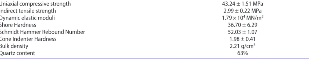
Simulating the actual cutting action of picks depends upon the type of tool lacing, as numerous design combinations are available in practice. Tools having their axes parallel to each other, like vane picks found on the cylindrical surface of a cutting drum with zero degree tilt angle, were considered for simplicity. The perimeter of a cutting sequence formed by tools of this type, normally describes a slope (angle of inclination) rather than a horizontal line during actual cutting, due to transverse motion of tools with helical arrangement as seen in Figure 2. A horizontal perimeter was, however, preferred for the sake of simplicity. The cutting action of a shearer drum of fixed web depth, fitted with two vanes (two spirals) and operating at 12 mm advance per revolution, was simulated at different tool spacing. A fine-grained homogeneous and isotropic sandstone obtained from Springwell, England, was used for the cutting experiments, since the scope of the investigations was to compare the variables under the same conditions. Some mechanical and physical properties of the rock sample are presented in Table 1.
Laboratory full-scale linear cutting trials were conducted by a 0.66 m instrumented shaping machine capable of producing in-line thrust force of 50 kN, at the University of Newcastle Upon Tyne in England (Figure 7). Radial picks having −5° rake angle and 10° back clearance angle with 50 mm gauge (tool reach), designed for cutting medium strength rocks, and slender-type point attack picks, having 75° cone angle and 55° angle of attack were used. Slender-type picks were preferred due to limitation of machine which could not withstand to high forces that are generated by heavy duty picks. Utmost care was paid to use sharp picks for each single cut throughout the cutting trials. The trials were car-ried out both in groove deepening and relief cutting for all levels of parameters as shown in Table 2.
Initially, the experiments were carried out on flat surface of the rock sample to obtain data on con-ventional cutting procedure. For simulated cuttings, the rock surface was initially trimmed and then
Table 1. Some mechanical, physical and mineralogical properties of the rock sample.
uniaxial compressive strength 43.24 ± 1.51 MPa
Indirect tensile strength 2.99 ± 0.22 MPa
dynamic elastic moduli 1.79 × 10⁴ Mn/m2
Shore Hardness 36.70 ± 6.29
Schmidt Hammer rebound number 52.03 ± 1.07
cone Indenter Hardness 1.98 ± 0.41
Bulk density 2.21 g/cm3
Quartz content 63%
Figure 7. Instrumented shaping machine used for laboratory linear cutting experiments.
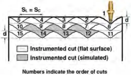
coated with paint. The simulated cuts were not instrumented until a stabilised cutting regime which was perceived by disappearance of painted surface and consistent groove profiles, was reached, This procedure is illustrated in Figure 8 as an example for groove deepening trials, and similar procedure is also the case with relief cutting. Debris collected for each cut was weighed and corresponding cutting and normal force components were recorded, and the specific energy was calculated.
2.2. Results of laboratory linear cutting trials
It is important to note that the trials for groove deepening with radial picks could only be carried out up to s/d value of 6, since the shaping machine was stalled at s/d of 8 (Figure 9). Following experi-ments planned for groove deepening with point attack picks, therefore, had to be abandoned to avoid a potential damage to the shaping machine. The trials for relief cutting were, however, successfully resumed for the all s/d values planned for both pick types.
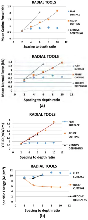
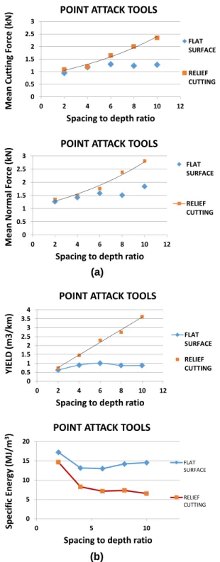
Variations in mean tool forces, yield and specific energy with s/d ratios are presented for radial tools and for point attack tools, respectively, in Figures 10 and 11. The cutting force and normal force components increased towards higher values of s/d for both modes of cutting. The groove deepening,
Table 2. the parameters investigated during linear cutting experiments.
Variables Levels Description
cutting modes 3 groove deepening, relief cutting, trimmed surface cutting
cut spacing (S) 5 12 mm, 24 mm, 36 mm,48 mm, 60 mm
depth of cut per start 1 6 mm
advance per revolution 1 12 mm
Pick type 2 radial pick, Point attack pick
rock type 1 Springwell Sandstone, england
replications 4
Figure 8. description of instrumented cuts for groove deepening trials.
Figure 9. Machine stalling during simulation experiments with groove deepening at s/d of 8.
D
Instrumented cut (flat surface)D
Instrumented cut (simulated)however, exhibited higher values than did relief cutting for the all s/d values except 2. Magnitude of forces with point attack tools was higher than that radial picks. Ratio of normal force to cutting force was less than 1 for radial tools, whilst being vice versa for point attack tools. The values for yield shown in Figures 10(b) and 11(b), indicate that in both cutting modes the same cross-sectional areas were physically removed with tool forces of different magnitudes at all s/d values but 2. With relief cutting
(a)
(b)
Figure 10. variation of (a) mean tool forces, and (b) yield and specific energy with spacing to depth ratios measured for flat surface, relief cutting and groove deepening with radial tools.
572
@
O. Z. HEKIMOGLUz
2.5 ~ QI 2 ~ 0 1.5...
bO C: E 1 ::, u 0.5 C:..
QI 0 :ii 0z
1.4 ~ QI l.2 u l...
0....
0.8 ;;; 0.6 E 0 0.4 2 0.2 s::..
0 QI ~ 0 4e
3.5 ~ 3 ... tl'l 2.5.5.
2 C 1.5 -' 1 LO.I 0.5>
0 0 '" E 12 ...~
10 8 > !!.II 6 QI s:: LO.I 4 u Ii: 2 ·.:; QI 0 C. Ill 0 RADIAL TOOLS •FLAT SURFACE • RELIEF CUTTING -"GROOVE DEEPENING 2 4 6 8 10 12Spacing to depth ratio
RADIAL TOOLS FLAT SURFACE •REUEF CUTIING GROOVE DfiPENING 2 4 6 8 10 12
Spacing to depth ratio RADIAL TOOLS • / /2 ~
.,,,.
,
- /"'-_, 2 4 6 8 10Spacing to depth ratio
RADIAL TOOLS A.
•
& A-~
--
"'-2 4 6 8 - + -FLAT SURFACE • RELIEF CUTTING -;..--GROOVE DEEPENING 12•
• FLAT SURFACE ---RELIEF CUTTING GROOVE DEEPENING 10 12the specific energy decreased rapidly up to s/d of 4 and then more slowly after this value, whereas it was higher with groove deepening than relief cutting for all measured s/d ratios except 2, and ceased
(a)
(b)
Figure 11. variation of (a) mean tool forces, and (b) yield and specific energy with spacing to depth ratios measured for flat surface and relief cutting with point attack tools.
z
POINT ATTACK TOOLS=-
3 QI 2.5 u • FLAT..
0...
2 SURFACE tu) 1.5 CE
:::, 1 • RELIEF u 0.5 CUTTING C n, 0 QI ~ 0 2 4 6 8 10 12Spacing to depth ratio
POINT ATTACK TOOLS
z
3=-
• FLAT QI 2.5 u SURFACE..
0 2...
ia 1.5 E ---RELIEF..
1 0 CUTTING z C 0.5 n, 0 QI ~ 0 2 4 6 8 10 12Spacing to depth ratio
POINT ATTACK TOOLS
4
e
3.5 ~ 3 ... -+-FLAT f'/l 2.5 .§. 2 SURFACE Q 1.5...
1 • RELIEF w>
0.5 CUTTING 0 0 2 4 6 8 10 12Spacing to depth ratio
POINT ATTACK TOOLS
-M 20 E ......
~ 15 FLAT > SURFACE tu)..
10 QI C w RELIEF u 5 ;;:::: CUTTING ·.; QI 0 12. Ill 0 5 10to exist after s/d value of 6. The results of trials on flat rock surface indicated that minimum specific energy tends to occur between s/d values of 4 and 5.
The average breakout angle for unrelieved cutting on flat rock surface was measured to be around 66° for radial picks, while being approximately 67.5° for point attack picks. The breakout angles were observed to vary with s/d values of each cutting mode in such a way that being asymmetrical at s/d of 2, and reasonably symmetrical at s/d of 4, and beyond this value they were not consistent. The highest breakout angle observed for groove deepening was found to be always lower than that of unrelieved cut on flat rock surface, whereas the opposite was true for relief cutting mode.
3. Discussion
3.1. On the geometrical method for pick force calculation
Before proceeding to the discussion, it is worth to consider the findings reported by Hurt and Evans [5]. They noted that when cutting with point attack picks, the rock surface disintegrates into a series of scallops which have an approximate ‘V’ cross section, and the apex angle of ‘V’ (half of which is also known as `breakout angle) showed a roughly constant value in experiments where depth of cut and tool angle were varied. The failure surfaces were assumed to be planes at right angles to the plane of the diagram making angles θ with the vertical, and thus a V-shaped section of rock is removed as given in Figure 12. The breakage mechanism observed with groove deepening and relief cutting during the laboratory simulation trials described in this paper may be explained better on the bases of V-shaped cross section of grooves. The main objective of this discussion is to establish a relationship between measured tool forces and the geometry of relative profiles of adjacent grooves, rather than constructing a mathematical model.
It is to note that at s/d value of 4 there is no significant difference between the respective values of tool forces measured for flat surface cutting and relief cutting with radial picks; in fact they are almost equal with the case of point attack picks, as in Figures 10(a) and 11(a). The corresponding yield values for flat surface cutting were also found to constitute nearly 55–60% of those of relief cutting, indi-cating that at s/d of 4, the cross-sectional area swept in relief cutting is about 40–45% more than that of flat surface cutting (Figures 10(b) and 11(b)). Furthermore, the magnitude of tool force required for sweeping the area of triangle ABC in flat surface cutting (Figure 13(a)) is very similar or almost equal to that required to remove the total area of polygon ACDB in relief cutting, as shown in Figure
13(b). Therefore, with relief cutting, the extra cross-sectional area of triangle ABC at the top portion of the polygon can be discarded, since it does not impose any confinement on the cutting action of the pick. Otherwise the magnitude of tool forces with relief cutting should have been about 40–45% more than those of flat surface cutting. The effective cutting action of the tool, then, seems to take place within an area depicted by a triangle which has an apex angle twice the breakout angle of the rock, and with a base line defined by a point where the confined side of apex angle intersects with free surface, or the longer side instead, if there is no tool confinement. The part remaining within this
Figure 12. Illustrations of assumptions for theoretical calculation of breakout angle (θ) [5].
BCD triangle may be considered as an ‘effective area’, for tool force calculations. The methodology for construction of triangles representing effective areas may be better explained, if profile views of the grooves cut by adjacent tools are taken into account, in accordance with observations during the simulation trials, as follows.
The state of breakouts at s/d of 2 is illustrated in the form of conceptual drawings in Figure 14. The bold line denotes the profile view of grooves already cut by the neighbouring tools. With both cutting modes, the pick hits the rock at point C, and tends to break it by forming a ‘V-shaped’ groove with an apex angle twice normal breakout angle of rock obtained from unrelieved grooves on flat rock surface. The point at which the longer side of this angle or any side which lies in the confined section of cut, intersects with free rock surface (the point B in the figure) determines the location of base line
Figure 13. the profile view of breakouts between adjacent grooves at s/d value of 4, observed during the laboratory trials; θ is half breakout angle, d is depth of cut and SC is cut spacing.
Figure 14. depiction of breakouts at s/d of 2.
TOOL AXIS
-
1 ~
__j -~ d d THE A DJA,CENT TOOl Sc ; C a) Flat surface TOOL AXIS b) Relief cutting EFFECTIVE AREA. s/d=
2 Relief cutting AREA SWEPT BY~ ,
=
~
·
B
·
~
/
5ikbM
[ Sc / C EFFECTIVE AREA 1of the isosceles triangle ABC. The last point (the point E) where the base line intersects with an uncut rock surface while moving from B up to A defines the length of upper boundary of the effective area which is the length of line EB in the figure. Any part of rock lying below this line, whether previously cut or uncut, is counted in the effective area (the shaded areas in the figure), while those areas which are above this line is totally discarded. During the trials, the longer side of the apex angle was seen to terminate easily through point B for both cutting modes. This is because the tool is able to exert its full potential without any confinement, due to very close tool spacing.
At s/d of 4, with relief cutting, the tool hits the rock at point D, and the right side of the apex angle tends to terminate at point E through point C, in an effort to create its complete breakout angle (Figure
15(a)). During the trials, the fracture was, however, seen to terminate at the nearest free surface located at point B, meaning that the pick is unable to create its complete breakout angle. A question may, then, arise in such that why the fracture did not terminate at point E as it did so with groove deepening at s/d of 2? This may be attributed to the fact that the tool is unable to exert its full potential at s/d of 4, due to greater pick spacing which is twice that of s/d of 2. The tool was, therefore, too confined to induce the intended fracture at the target point of E. Under such a circumstance, the respective values of s/d, however, needs to be defined to avoid misleading calculations, if a computer programme on tool lacing is concerned. However, no problem is likely to arise from this issue, since such a lower s/d values is not usual in tool lacing. The above-mentioned tool confinement has to be taken into account with the effective area. It may be defined by an additional areal value of a triangle (BCD) added to that of the main triangle (ACD) to obtain the total effective areal value, as shown in Figure 15(a). With groove deepening, the rock fracture was observed to terminate at Point B which defines the location for the base line of the isosceles triangle (Figure 15(b)). It is to note that the uncut rock above the base line was discarded, since it is out of the effective area, as explained in Figure 13. The effective area (the shaded area in the Figure 15(b)) calculated for groove deepening was higher than that of relief cutting, indicating the higher tool forces with groove deepening as measured at this s/d.
The state of profiles of grooves at s/d of 6 is shown for both cutting modes, respectively, in Figure 16. The groove surfaces were observed to be no longer smooth, while being more pronounced with groove deepening which also exhibited greater effective areas, compared to previous s/d values, probably due
Figure 15. depiction of breakouts at s/d of 4 (a) for relief cutting and (b) for groove deepening.
576 O. Z. HEKIMOGLU AREA SWEPT av THE ADJACENT TOOL S0 s/d = 4 Relief cutting (a) AREA SWEPT BY
THE ADJACENT TOOL
d
EFFECTIVE AREA
s/d = 4 Groove deepening
{b)
to higher tool spacing. Much more irregular grooves particularly with groove deepening were observed at s/d of 8, as shown in Figures 9 and 17(b). This was probably the reason why the tools were failed to accomplish cutting at this stage of the simulation trials with groove deepening.
The method described above may be validated by plotting all measured tool force values against the all calculated areal values for both relief cutting and groove deepening together. It is seen that there is a good correlation between tool forces and their corresponding effective areas for both modes of cutting with both radial and point attack tools (Figure 18(a) and (b)). It is also important to emphasise that for the sake of simplicity and reliability, the breakout angle adopted for this method is that obtained from unrelieved cuts on a flat rock surface. This was because it was difficult to obtain a consistent value from relieved cutting.
Figure 16. depiction of breakouts at s/d of 6.
Figure 17. depiction of breakouts at s/d of 8 (a) for relief cutting and (b) for groove deepening. AREA SWEPT BV
,~
ti
!~=-::;~
8 1 d 1 S, c f - .c.EFFECTIVE AREA= ABC s/d = 6 Relief cutting
AREA SWEPT av
THE ADJACENT TOOL TOOL AXIS
'
S/d " 6 Groove deepening
TOOL AXIS
~
i Sc IC...
EFFECTIVE AREA= ABC
s/d
= 8 Relief cutting(a)
EFFECTIVE AREA= SHADED AREA
s/d
= 8 Groove deepening(a)
(b)
Figure 18. correlation of mean tool forces with effective areas for (a) for radial tools and (b) for point attack tools.
578 O. Z. HEKIMOGLU
z
combined with groove deepening) RADIAL PICKS (Relief cutting: . 2.5 ~ -(11 ~ 2+ - - - -~ ~ '--- -0 ~ 1.5 C
E
1+ - - ---:.~ =---- -:::, U 0.5 C y = 0.0074x + 0.2936 R2 = 0.9192 ~ 0 + ~ -::!!: 0z
: , 1.6 (II 0.8 100 200 300 Effective Area (mm2)RADIAL PICKS (Relief cutting combined with groove deepening)
• ~ if iii E
...
0 z C Ill (II 0.4 + - - - ~Y = 0.004x + 0.39 _ R2 = 0.901 0 + - - - ~ - - - - ~ - - - , ::!!: 0 100 200 Effective Area (mm2)POINT ATTACK TOOLS (Relief cutting)
Z 3
-
=-300 0 + - - - ~ 0 50 100 150 200 250 Effective Area (mm2)POINT ATTACK TOOLS (Relief cutting)
cu 2.5 + - - - ..-::-~ -~ if 2 + - - - -~ .C... -iii 1.5 +---c---=-F- -E
s
1 + -zc 0_5 y = 0.0096x + 0.7736 R2 = 0.9893 ~ 0 + - - - ~ - - ~ - - ~ - - ~ - - ~ ::!!: 0 50 100 150 200 250 Effective Area (mm2)The experiments also demonstrated that confined area is particularly the case for relief cutting, and it occurred immediately below the s/d ratio where the interaction between the adjacent grooves takes place at a line spacing equals ‘2 d tan θ’. This, hence, indicates that the line spacing for relief cutting should not be set below this critical ratio, and it should be equal to or slightly greater than this value.
The concept of this method may be verified by considering experimental data from previous studies in a similar aspect. The first group of data was related to full-scale laboratory linear cutting simulation experiments on the effects of variation in the angle of wraps of a cutting sequence on tool forces and specific energy [29]. Four different angle of wraps corresponding the angle of inclinations of a given cutting sequence, being 0°, 10°, 20° and 30°, were considered. Tool forces and specific energy were found to be minimum at 10°, while being maximum at 30°. The results also showed that tool forces were different for each cutting sequences, despite the fact that the same cross sections of rocks were cut. This was attributed to differences in tool cutting position which was defined by ‘effective depth’. A good correlation was reported between the measured tool forces and corresponding ‘effective depth’, as shown in Figure 19. The changes in tool forces can also be evaluated by calculating the effective cross-sectional areas for each angle of inclination, using the triangular method explained in this paper. The conceptual drawings for effective areas related to each angle of inclination are presented in Figure
20, in considerations with the profile view of adjacent grooves observed during these trials. The tool was seen to be confined at one side of its axis for all cases but at 20° angle of inclination (Figure 20(c)). It is important to note that the base line with 10° angle of inclination is located at point B, because it lies in the confined side of the cut (Figure 20(b)). The longer side along the line DC was, therefore, not considered, since the cut is unconfined at this portion. The calculated values of effective areas corresponding to angle of inclinations appear to be in good agreement with the corresponding tool forces, as shown in Figure 21.
The second data related to a research study previously carried out on the performance of chain saw machines, with respect to tool lacing [7]. The cutter tools were originally arranged in grove deepen-ing with 13 tools in each cuttdeepen-ing sequence. This lacdeepen-ing was decided to be modified to relief cuttdeepen-ing. Only the first three tools of this cutting sequence could, however, be rearranged in relief cutting. The original lacing was, then, compared to the partially modified lacing in situ under the same conditions. The cutting speed of machine was seen to increase by around 25% at the same power consumption. This improvement was attributed to significant decreases in tool forces acting on the rearranged first three tools which were usually subjected to higher tool forces. The force acting on the first tool, was reported to be the highest among all picks in the cutting sequence for this particular pick lacing. The forces generated by these tools can be calculated for both lacing arrangements, through the effective cross-sectional area method described in this paper. The values of effective areas related to each pick were calculated for original lacing (groove deepening) and partial modification (relief cutting),
Figure 19. correlation of mean forces with effective depth of cut for each angle of inclination [29].
s
~---.
z
7""
y; 0.3966x - 0.8538, ; ' 6 '" 0.9.85. CII ::! 5 0 •Normal LL C 4 OI CII • Cuttlng === 3""
~ 2 •Side ::I.,,
OI CII :Ii: 0 5 10 15 20respectively. These areas were, then, correlated with an empirical equation reported previously to obtain tool forces [7]. The force values used in this empirical equation were those of a similar rock, not necessarily that of the rock investigated, since the main purpose was only to compare the level of tool forces, rather than specifying the actual values. As a result of calculation, mean cutting forces with rearranged picks were found to be lower than those with the original picks, and the highest tool force was the case with the first tool which was designated as Pick 1 in Figure 22. It is very important to emphasise that misleading results would have been obtained, if physically cut cross-sectional areas
Figure 20. depiction of effective areas for each angle of inclination.
Figure 21. correlation of mean forces with effective areas for each angle of inclination.
580 O. Z. HEKIMOGLU
I I I
I
EHECTIVE AREA= SHADED AREA+ ABO Angle of inclination = o"
(a)
EFFECTIVE AREA= SHADED AREA
s
Angle of inclination= 20° (c) 8z
~ 7 Ill CII 6 ~ 0 5....
y= C ra 4 GI ~ 3.,,
GI 2...
:, Ill 1 ra CII ~ 0 100 300 Angle of inclination = 10° ~ EFFECTIVE AREA= SHADED AREA+ DCBAngle of inclinat{on = 30° (d) • CUTTING FORCE • NORMAL FORCE y = 0.0088x -2.1206 .l SIDEWAYS R =0.9866 FORCE 500 700 Effective Area (mm2)
were considered alone, instead of effective areas. As an example, with groove deepening the physically removed cross-sectional area by the first tool is much smaller than the effective area (Figure 23(a)), whereas it is vice versa with relief cutting (Figure 23(b)).
In this study, the effective area method was used to explain the reason for generation of higher forces with groove deepening. The method also showed why the tool forces were different despite the fact that same cross-sectional areas were cut at different angle of inclinations of given cutting sequences. Furthermore, the fact that how the first tool on a given chain saw machine exhibited the highest cutting force among all picks, was also explained. The method is simple and free from complicated assump-tions. Moreover, it may be applied for a given relieved cutting condition without requiring any cutting factor, if the value of breakout angle related to rock properties and tool conditions is known. The value of breakout angle inevitably changes with rock types and tool characteristics, e.g. whether the tool is pristine or worn. It is, however, very important to note that such variations may not be influential in this respect, since the method merely involves the construction of a triangle which is entirely based upon the value of breakout angle that has to be specified for a particular condition. In other words, the triangles can be constructed for any condition, as long as a breakout angle is defined for a specific case. It was, therefore, thought to be reasonable to suggest it as a pick force calculation method for computer-aided assessment of tool lacing. However, it is worth to emphasise that this method can be improved by further studies, since it was investigated and proven within limited set of conditions.
3.2. On tracking cutters and tool spacing
The advantages demonstrated with relief cutting over groove deepening may be explained by consid-ering the state of rock fracture in relation to the spatial position of tools during cutting. With relief cutting, the line spacing can be easily set in fractions of cut spacing, e.g. half of cut spacing as with this study, whereas this is absolutely impossible with groove deepening, since the picks have to follow exactly the path of tools located in the preceding sequence. As a result of this, the point on a free surface where the rock fracture terminates emerges to be much closer to the pick tip in relief cutting than that in groove deepening. The effective areas with groove deepening are, therefore, greater, particularly after the s/d value where interaction between adjacent grooves takes place. It is probably for this reason why tools in groove deepening ceased to cut after the s/d value of 6, while the cutting successfully resumed in relief cutting with all s/d values investigated during the laboratory trials. This
Figure 22. distribution of individual tool forces for a chain saw machine [7]. 0.395 z 0.39 .¥ QI 0.385
-u
...
0.38 0 ~ tlO 0.375 C .; 0.37-
::I u 0.365 C 111 0.36 QI ,_ ~ 0.355 -0.35 1 2•
GROOVE DEEPENING (D = 0.93 mm)•
GROOVE DEEPENING PARTIALLY COMBINED WITHRELIEF CUTTING (D = 1.11 mm)
-
-1---
1-- 1--1---
' - 1-- 1--1---
>--
1---
1-- 1--- 1-- ,_ - 1-- 1-- 1-- - 1---- -
-- - -
--ti
' --
' -3 4 5 6 7 8 9 10 11 12 13 14 Order of Picks -~merit makes the relief cutting more advantageous when cutting in cycloidal motion, and also helps to explain the trend of force variations presented in Figure 4. The depths begin with zero, and ultimately terminate at maximum value of 8 mm at fixed tool spacing, due to the characteristics of cycloidal cutting. In reality, each value of cutting depths shown along ‘x axis’ of the graph also represent their corresponding s/d ratios in a reverse order, e.g. at 6 mm depth the corresponding s/d is 3, while at 2 mm depth it is 9. The higher force values occurring at shallow depths or at higher s/d values with groove deepening is attributed to the generation of much greater tool forces at higher s/d ratios as observed during the laboratory simulation trials described here in this study.
The trials also demonstrated that with relief cutting, specific energy initially showed sharp decrease up to s/d between 4 and 5, and kept decreasing slowly, after this point. This may infer that s/d values higher than that what is known ‘optimum s/d’ in flat surface cutting may also be considered for a tool lacing. This idea should, however, be compatible with other parameters, such as drum balance and torque. An imaginary drum having two starts with fixed dimensions was considered to evaluate this idea, in terms of specific energy, torque and torque fluctuations which were standard deviations of mean torque values. Only vane tools were assumed to exist on the whole drum surface, to avoid complicated corner cutting situation. The calculations were carried out at 90° cut sector for each s/d, respectively, at a constant advance per revolution, and the results are presented in Table 3.
(a)
(b)
Figure 23. notation of effective areas and physically removed areas for the chain saw investigated, (a) for groove deepening and (b) for relief cutting (the solid bold line denotes the uncut rock surface for both cutting modes).
Table 3. analyses of a sample drum in terms of torque, torque fluctuations and specific energy.
s/d Mean torque (kNm) Torque fluctuations (kNm) Volume of cut material per ‘Adv/rev’ (10−3 × m3) Specific energy (MJ/m3)
2 2.509 ± 0.087 1.0368 15.20 4 1.387 ± 0.103 1.0368 8.40 6 1.263 ± 0.140 1.0368 7.65 8 1.162 ± 0.174 1.0368 7.04 582 O. Z. HEKIMOGLU TOOL AXIS
-
PHYSICAL:
A:l'ii"B
--.;::IC~-REMOVED AREA L::..
EFFECTIVE AREA= ABC
Previous lacing (Groove deepening)
TOOL AXIS
!B
~[Pc-~
EFFECTIVE AREA = ACD
PHYSICALLY REMOVED AREA= POLYGON (ABCD)
As seen, the decrease in both specific energy and drum torque is not significant after s/d value of 4, while torque fluctuations rise considerably. The drum balance is known to be inversely affected, as the total number of tools decreases. It is important to note that the fluctuations in torque are related to the availability of full depth of sump throughout the course of cutting process. In practice, the drums and cutting heads do not always operate in full depth of sump, owing to changing face and operating conditions. Under such circumstances, the total number of active picks ‘in cut’ will reduce, and level of fluctuations in both torque and reaction forces will consequently increase. Fluctuations in torque and reaction forces always have to be avoided, since they inflict heavy damages on major machine components. Hence, the s/d values higher than optimum s/d value which is between 4 and 5 for these experiments are not suitable, since a small decrease in both specific energy and torque after this value cannot be afforded at the expense of high vibrations.
4. Conclusions
A comparison of groove deepening to relief cutting was carried out with both radial and point attack picks. During the laboratory trials the profile geometry of adjacent grooves with an approximate ‘V’ cross section was observed. Within the limit of results and experimental conditions, as well as the limit of rock type and parameters investigated, following conclusions may be drawn:
1) The top portion of the cross section of a groove did not impose any significant effect on the magnitude of tool forces. The rock fracture effectively took place mainly in the lower portion of the whole cross section described by a triangle which has an apex angle twice the breakout angle of unrelieved groove. The areal quantity of this triangle considered together with tool confinement which was termed ‘effective area’ was employed to calculate the tool forces. The calculated effective areas were found to be in good correlation with the measured tool forces. This concept was also verified by a number of experimental data of previous investigations. The effective areas calculated for groove deepening were generally greater than those of relief cutting, accounting for higher tool forces observed with this cutting mode.
2) The effective area may be introduced as a tool force calculation method for computer assess-ment of tool lacing where tool forces are calculated through pick cross sections. The method is simple and involves a single-step calculation. The areal extent of the effective areas can be calculated without a number of assumptions, once the breakout angle of the rock and the spatial position of a given pick with respect to neighbouring tools were defined for a specific rock and tool condition. This method can be improved by further studies.
3) With simulated trials, specific energy decreased drastically at first and then slowly after s/d of 4. it, however, ceased to continue with groove deepening after s/d ratio of 6, due to greater effective areas, while being continuous with relief cutting at all s/d ratios investigated. There was no marked minimum specific energy value as emphasised with experiments on flat rock surface. However, tool spacing at which interaction between adjacent grooves takes place, i.e. at ‘2 d tan θ, may be recommended to avoid detrimental effects of fluctuations in torque and reaction forces.
4) The groove deepening mode of cutting should not be considered for mechanical excavators employing drag tools.
Acknowledgements
The author wishes to thank Dr R. J. Fowell (formerly at the University of Newcastle Upon Tyne, now at the University of Leeds) for his invaluable helps and guidance, and Turkish Coal Enterprises (TKI) for financial support. The views expressed here are the author’s own and not necessarily those of TKI.
Disclosure statement
No potential conflict of interest was reported by the author. References
[1] F.F. Roxborough, Cutting rock with picks, Min. Eng. 132 (June 1973), pp. 445–455
[2] F.F. Roxborough and A. Rispin, The mechanical cutting characteristics of the lower chalk, Tunnels Tunnelling 5 (1973), pp. 45–67.
[3] F.F. Roxborough and H.R. Phillips, The mechanical properties and cutting characteristics of the Bunter sandstone, Report by Department of Mining Engineering, University of Newcastle upon Tyne for Transport and Road Research Laboratory, Department of the Environment, England, 1975.
[4] I. Evans and C.D. Pomeroy, The Strength, Fracture and Workability of Coal, Pergamon Press, Oxford, 1966. [5] K.G. Hurt and I. Evans, Point attack tools: An evaluation of functions and use for rock cutting, Min. Eng. 140 (March
1981), pp. 673–675.
[6] O.Z. Hekimoglu, M. Ayhan, and B. Tiryaki, Laboratory and in-situ investigations of tracking cutters for computer-
aided design of shearer drums, CIM Bull. 96 (September 2003), pp. 72–75.
[7] O.Z. Hekimoglu, Studies on increasing the performance of chain saw machines for mechanical excavation of marbles
and natural stones, Int. J. of Rock Mech. Min. Sci. 72 (2014), pp. 230–241.
[8] H. Copur, Linear stone cutting tests with chisel tools for identification of cutting principles and predicting performance
of chain saw machines, Int. J. Rock Mech. Min. Sci. 47 (2010), pp. 104–120.
[9] Y. Sun and X.S. Li, Ineffective rock breaking and its impacts on pick failures, Proceedings of the 31st International Symposium on Automation and Robotics in Construction and Mining (ISARC 2014), Sydney, Australia, 2014, pp. 754-761.
[10] K.G. Hurt, Roadheader cutting heads: A study of the layout of cutting tools and a rational procedure for design, NCB MRDE Report, No: 90, England, 1980, pp. 28.
[11] K.G. Hurt and K.M. MacAndrew, Roadheader cutting heads: How many tools per line? MRDE Report 96, Bretby, England, 1981, pp. 10.
[12] K.G. Hurt, K.M. MacAndrew and C.J. Morris, Boom roadheader cutting vibration: Measurement and prediction, Proceedings of the Conf. Applied Rock Engineering, Newcastle Upon Tyne, 1988, pp. 89–97.
[13] K.G. Hurt and C.J. Morris, Computer designed cutting heads improve heads improve roadheader performance, Tunnels Tunnelling 17 (March 1985), pp. 37–38.
[14] J. Rostami, D. M. Neil, and L. Ozdemir, Roadheader application for the Yucca Mountain experimental study facility, Final report for Raytheon Services, Nevada Yucca Mountain Project, Earth Mechanics Institute, Colorado School of Mines, Las Vegas, Nevada, 1993.
[15] Y.F. Guo, Y.Z. Zhang, D.S. Liu, et al., Kinematics analysis and computer simulation on longitudinal cutting head of
roadheader, J. China Coal Soc. 27 (2002), pp. 68–72.
[16] S. Somanchi, V. Kecojevic, and T. Kozminski, Advance design of lacing and breakout patterns for shearer drums, Min. Technol. (Trans. Inst. Min. Metall. A), 114 (June 2005), pp. 118–124,
[17] S.Y. Liu, K.D. Gao, C.L. Du, and L. Fu, Experiment research on cutter arrangement of helical cutting mechanism, Adv. Sci. Lett. 4 (2011), pp. 1424–1429.
[18] X. Zhang, X. Liu, J. Zhang, and Q. Zeng, Multi-objective optimization design, and for cutting head of roadheader, Key Eng. Mater. 450 (2011), pp 75–78, Trans Tech Publications, Switzerland.
[19] K.D. Gao, C.L. Du, and S.Y. Liu, An empirical mathematic model of drums cutting torque, J. Theor. Appl. Inf.
Technol. 46 (December 31 2012), pp. 785–789.
[20] Q.Q. Zhang, Z.N. Han, and W.H. Liu, Comparison and analysis of cutting performance of longitudinal cutting heads
with various numbers of helical lines, Min. Mach. 41 (2013), pp. 12–16.
[21] X. Li, B. Huang, G. Ma, and S. Jiang, Intelligent design and simulation of roadheader cutting head, J. Chem. Pharm. Res. 6 (2014), pp. 2140–2146.
[22] L. Zhao, X. Liu and P. Liu, Influence of picks arrangement mode on shearer’s working performance, Mech. Sci. Technol.
Aerosp. Eng. 33 (December 2014), pp. 1838–1844. doi: http://dx.doi.org/10.13433.
[23] S. W. Choi, S. H. Chang, Y. T. Park, and G. P. Lee, Performance estimation of conical picks with slim design by the linear cutting. Test (I): Depending on attack angle variation, J. Korean Tunnelling Underground Space Assoc. 16 (2014), pp. 573–584.
[24] S. W. Choi, S. H. Chang, Y. T. Park, and G. P. Lee, Performance estimation of conical picks with slim design by the
linear cutting Test (II): Depending on Skew Angle variation, J. Korean Tunnelling Underground Space Assoc. 16
(2014), pp. 585–597.
[25] K. Krauze, R. Klempka, and K. Mucha, Computer-aided design of cutting heads, Min. – Inf. Autom. Electr. Eng. 4 (2015), pp. 22–32.
[26] S. Jiang, Q. Zeng, X. Zhang, and L. Wan, Parametric modelling of cutting head in a roadheader machine based on
nurbs in openGL, Rev. Téc. Ing. Univ. Zulia 39 (2016), pp. 397–404.
[27] J.S. Jang, W.S. Yoo, H. Kang, J.W. Cho, M.S. Jeong, S.K. Lee, Y.J. Cho, J.W. Lee, and Jamal Rostami, Cutting head
attachment design for improving the performance by using multibody dynamic analysis, Int. J. Precis. Eng. Manufac.
17 (March 2016), pp. 371–377.
[28] O.Z. Hekimoglu, Studies in the excavation of selected rock materials with mechanical tools, Ph. thesis (unpublished), The University of Newcastle Upon Tyne, England, 1984.
[29] O.Z. Hekimoglu and L. Ozdemir, Effects of Angle of wrap on the performance of continuous miners and drum
![Figure 3. effect of cut depth and spacing on (a) mean cutting force and (b) specific energy [ 5 ].24 z20 .:.:: -QI f 16 0 u](https://thumb-eu.123doks.com/thumbv2/9libnet/3843259.34154/5.739.202.529.74.720/figure-effect-depth-spacing-cutting-force-specific-energy.webp)
![Figure 4. variation of mean cutting force with depth of cut at constant spacing [ 6 ].](https://thumb-eu.123doks.com/thumbv2/9libnet/3843259.34154/6.739.242.498.79.224/figure-variation-mean-cutting-force-depth-constant-spacing.webp)
![Figure 6. Illustration of tool confinement for various tool positions [ 10 ].' Rock suriace ! ilu ___ ,__ --...:---L ,, ,,](https://thumb-eu.123doks.com/thumbv2/9libnet/3843259.34154/7.739.91.649.77.437/figure-illustration-tool-confinement-various-positions-rock-suriace.webp)
![Figure 12. Illustrations of assumptions for theoretical calculation of breakout angle (θ) [ 5 ].](https://thumb-eu.123doks.com/thumbv2/9libnet/3843259.34154/12.739.242.500.813.963/figure-illustrations-assumptions-theoretical-calculation-breakout-angle-θ.webp)
