REAL TIME PHYSICS-BASED
AUGMENTED FITTING ROOM USING
TIME-OF-FLIGHT CAMERAS
a thesis
submitted to the department of computer engineering
and the graduate school of engineering and science
of bilkent university
in partial fulfillment of the requirements
for the degree of
master of science
By
Umut G¨
ultepe
July, 2013
I certify that I have read this thesis and that in my opinion it is fully adequate, in scope and in quality, as a thesis for the degree of Master of Science.
Assoc. Prof. Dr. U˘gur G¨ud¨ukbay (Advisor)
I certify that I have read this thesis and that in my opinion it is fully adequate, in scope and in quality, as a thesis for the degree of Master of Science.
Prof. Dr. ¨Ozg¨ur Ulusoy
I certify that I have read this thesis and that in my opinion it is fully adequate, in scope and in quality, as a thesis for the degree of Master of Science.
Asst. Prof. Dr. Ahmet O˘guz Aky¨uz
Approved for the Graduate School of Engineering and Science:
Prof. Dr. Levent Onural Director of the Graduate School
ABSTRACT
REAL TIME PHYSICS-BASED AUGMENTED
FITTING ROOM USING TIME-OF-FLIGHT CAMERAS
Umut G¨ultepe
M.S. in Computer Engineering
Supervisor: Assoc. Prof. Dr. U˘gur G¨ud¨ukbay July, 2013
This thesis proposes a framework for a real-time physically-based augmented cloth fitting environment. The required 3D meshes for the human avatar and apparels are modeled with specific constraints. The models are then animated in real-time using input from a user tracked by a depth sensor. A set of motion filters are introduced in order to improve the quality of the simulation. The physical effects such as inertia, external and forces and collision are imposed on the apparel meshes. The avatar and the apparels can be customized according to the user. The system runs in real-time on a high-end consumer PC with realistic rendering results.
Keywords: cloth simulation, computer vision, natural interaction, virtual fitting room, kinect, depth sensor.
¨
OZET
UC
¸ US
¸ ZAMANI KAMERALARI KULLANAN
GERC
¸ EK ZAMANLI F˙IZ˙IK TABANLI
ARTTIRILMIS
¸ G˙IY˙INME KAB˙IN˙I
Umut G¨ultepe
Bilgisayar M¨uhendisli˘gi, Y¨uksek Lisans Tez Y¨oneticisi: Do¸c. Dr. U˘gur G¨ud¨ukbay
Temmuz, 2013
Bu tezde ger¸cek zamanlı fizik tabanlı bir artırılmı¸s giyinme kabini ortamı i¸cin bir ¸calı¸sma ¸cer¸cevesi ¨onerilmektedir. ˙Insan avatarı ve kıyafet i¸cin gerekli ¨u¸c boyutlu modeller ¨ozel sınırlar ¸cer¸cevesinde modellenmi¸stir. Bu modeller daha sonra bir derinlik alıcısı tarafından takip edilen bir kullanıcıdan alınan girdi ile ger¸cek zamanlı olarak hareket ettirilmektedir. Sim¨ulasyon kalitesini arttırmak amacı ile hareketler ¸ce¸sitli filtrelerden ge¸cirilmektedir. Eylemsizlik, dı¸s kuvvetler ve ¸carpı¸sma gibi dı¸s etkenler kıyafet modeline uygulanmaktadır. Avatar ve kıyafet modelleri, kullanıcının boyutlarına g¨ore ¨ozelle¸stirilebilir. Sistem ¨ust kalite bir ki¸sisel bilgisayar ¨uzerinde ger¸cek zamanlı olarak ger¸cek¸ci g¨or¨unt¨uler olu¸sturarak ¸calı¸smaktadır.
Anahtar s¨ozc¨ukler : kıyafet sim¨ulasyonu, bilgisayarla g¨or¨u, do˘gal etkile¸sim, sanal giyinme kabini, kinect, derinlik sens¨or¨u.
Acknowledgement
I would like to express my sincere gratitude to my supervisor Assoc. Prof. Dr. U˘gur G¨ud¨ukbay, who guided and assisted me with his invaluable suggestions in all stages of this study. I also chose this area of study by inspiring from his deep knowledge over this subject.
I am very grateful to my jury members Prof. Dr. ¨Ozg¨ur Ulusoy and Asst. Prof. Dr. Ahmet O˘guz Aky¨uz for reading and reviewing this thesis.
I would like to thank Computer Engineering Department of Bilkent University for providing me scholarship for my MS study. I also would like to thank the Scientific and Technical Research Council of Turkey (T ¨UB˙ITAK) and the Turkish Ministry of Industry and Technology for their financial support for this study and MS thesis.
v
Contents
1 Introduction 1
1.1 Our Approach . . . 3
1.2 System Architecture . . . 4
1.3 Organization of the Thesis . . . 5
2 Related Work 6 2.1 Human Body Modeling And Animation . . . 6
2.1.1 Human Body Modeling . . . 7
2.1.2 Human Body Animation . . . 8
2.2 Motion Capture Systems . . . 9
2.2.1 Non-Optical Motion Capture Systems . . . 9
2.2.2 Optical Motion Capture Systems . . . 10
2.3 Cloth Modeling and Simulation . . . 11
2.3.1 Cloth Design and Modeling . . . 11
CONTENTS vii
2.4 Virtual Fitting Rooms . . . 15
3 Human and Cloth Modeling 17 3.1 Human Avatar . . . 17
3.1.1 Rigging . . . 18
3.1.2 Material Properties . . . 19
3.2 Cloth Mesh . . . 20
3.2.1 Body Positioning and Splitting the Dress Mesh . . . 20
4 Animation 23 4.1 Initialization . . . 23
4.2 Animation . . . 24
4.3 Interaction Between the Body and Cloth . . . 26
4.4 Motion Filtering . . . 27
4.4.1 Position Filtering . . . 27
4.4.2 Rotation Filtering and Constraints . . . 28
4.4.3 Bone Splitting . . . 29
4.5 Handling the Foot Skating Problem . . . 32
5 Cloth Simulation 37 5.1 Model Setup . . . 37
CONTENTS viii
5.3 The Animation . . . 39
5.4 Numerical Solution . . . 41
5.4.1 Constraints, Fibers and Sets . . . 42
5.4.2 Set Solvers . . . 42
5.5 Collision Handling . . . 43
6 Cloth Resizing 45 6.1 Depth Map Optimization . . . 46
6.2 Parameter Measurement . . . 47
6.3 Human Body Parameters . . . 48
6.4 Temporal Optimization and Scaling . . . 52
7 Experiments 54 8 Conclusions and Future Work 60 8.1 Future Work . . . 62
Bibliography 63 Appendices 73 A OGRE Framework 73 A.1 The Features . . . 74
CONTENTS ix
A.2.1 The Root Object . . . 75
A.2.2 The RenderSystem Object . . . 75
A.2.3 The SceneManager Object . . . 76
A.2.4 Resource Manager . . . 76
A.2.5 Entities, Meshes, Materials and Overlays . . . 76
B User Tracking 78 B.1 Hardware . . . 78 B.2 Software . . . 79 C Hand Tracking 80 C.1 OpenCV . . . 80 C.2 The Process . . . 80
List of Figures
1.1 The overall virtual dressing framework . . . 4
3.1 The rigging base skeleton. . . 18
3.2 The vertex weights for the Humerus.R bone. . . 19
3.3 Detailed appearance of the face. . . 20
3.4 The dress, positioned on the body, along with the upper-part of the skeleton. In this shot, the dynamic part is highlighted with orange border. . . 22
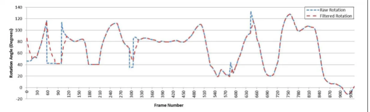
4.1 The row and filtered samples for right the humerus roll angle. . . 28
4.2 The vertex weights for (a) the upper ulna and (b) the lower ulna bone (weight increases from blue to yellow). . . 30
4.3 Comparison of a -90◦ yaw rotation on the forearm with: (a) single and (b) double-boned skinning. . . 31
5.1 The fixed vertices of the cloth. . . 38
5.2 Character formed with collision spheres and capsules. . . 44
LIST OF FIGURES xi
7.1 The frame rates for two different apparel meshes. . . 55 7.2 The corrected displacement of feet. The local minima correspond
to constrained foot changes and subsequent position smoothing. The zig zag regions correspond to time intervals where the user performing body yaw motion where the foot are considerably sliding. 55 7.3 An example depth map data and the corresponding posture of the
subject with a virtual cloth on it. . . 57 7.4 Examples of different garments on a model with different postures:
(a) sun dress, (b) jeans and vest, and (c) flight suit. . . 58 7.5 The designed apparel meshes for the male and female avatars. . . 59 C.1 The overview of the hand recognition algorithm . . . 81 C.2 Images and contours of hand regions from the depth stream. Left:
List of Tables
6.1 Kinect depth accuracy. . . 46 6.2 Human body proportions. Numbers in parenthesis represent the
lines on Figure 6.1. . . 50 6.3 Primary proportions for different cloth types. . . 50 7.1 Performance figures for five different subjects. . . 56 7.2 Performance comparison with other state-of-the-art approaches
List of Algorithms
1 Bone transformation algorithm . . . 25
2 Mesh update algorithm called at every frame . . . 34
3 Constrained foot determination . . . 35
4 Foot skating filtering . . . 36
5 Position-based dynamics solver . . . 41
6 Depth map optimization algorithm . . . 47
7 Sphere fitting algorithm . . . 49
8 Cloth resizing algorithm . . . 52
Chapter 1
Introduction
Computer graphics are being used in more and more areas today to help with visualization of data, such as in big data and crowd simulation. Human body animation and cloth simulation have been two significant subjects of the field for a while. Although there are cases where the simulation results are incredibly life-like, the task is still nothing trivial.
One of the most time-consuming stages of apparel shopping is the customer trying the apparels by putting them on, which is not even possible in online stores. With the advances in augmented reality technologies, virtual fitting rooms are slowly taking their places in both real and virtual stores [1, 2] to improve the quality of apparel trial experience while also making it faster. These frameworks utilize both humanoid and cloth animation features, hence they are limited by the bottlenecks in both fields. The demand for virtual dressing frameworks is increasing with the spread of online apparel commerce and the interactive ad-vertisement platforms. There are various features of virtual fitting frameworks, where each has different priorities in different types of applications:
• The apparel can be displayed on a virtual avatar or on real photos or videos of the user. The former is used more in design stages, the latter more in online and in-store try-on frameworks. Avatars can be static or dynamic, animated with the motions of the user or with pre-recorded animations.
• A virtual fitting room framework can utilize an apparel image database which consists of pre-recorded two dimensional photos of apparels in vari-ous poses to render the apparel, or it can utilize a virtual three dimensional model. Former approach is considered to require more preprocessing and cause lapses between poses, however the rendered apparel looks realistic as it is a two dimensional photo. Latter approach enables rapid three dimen-sional apparel model generation and more realistic material and physical simulations.
• If the three dimensional approach is used, the apparel mesh can be pro-cessed with physical simulation or can be stagnant. The former requires more advanced frameworks and more powerful hardware, making them more suitable for desktop applications rather than online fitting rooms.
• A virtual fitting room framework can scale the apparel and meshes accord-ing to the active user. The scalaccord-ing can be standardized where a fixed size among possible size options would be offered to the customer, or it can be detailed scaling similar to made-to-measure tailoring. The latter approach is more complex compared to the former, because a larger set of measure-ments are needed with higher precision.
On the low-end of the virtual fitting room spectrum, there are super positioned 2D images of the user and the apparel without any animation. Advanced virtual fitting rooms, on the other hand, show the apparel items either on the video of the user or on a virtual avatar, both scaled to reflect the user’s body characteristics [3]. Physics-based garment simulation for a better fitting experience is included in the high end frameworks [2]. Our approach utilizes a three dimensional virtual avatar which is updated with user motions captured through a depth sensor. The apparels are rendered as three dimensional models and updated with physical simulation.
1.1
Our Approach
This study is aimed to develop a novel virtual fitting room framework that pro-vides all the basic features expected from such an application, along with en-hancements in various aspects for higher realism. These enen-hancements include motion filtering, customized user scaling, and physics engine. Motion filtering process starts with temporal averaging of joint positions in order to overcome the high noise of the depth sensor. However, temporal averaging does not prove to be sufficient because unnatural movements take place due to limited recognition capabilities and self-occlusion. Customized joint angle filters, along with bone splitting to let limbs twist in a more natural way and footskate correction filters are implemented.
The avatar utilizes a skeleton that conforms with the LOA 2 of H-ANIM 200x specification [4], although not all bones are used for animation because of the data received from the depth sensor. The skeleton and mesh are modeled in Blender [5], exported and used in binary format. The simulated apparel pieces are also modeled in Blender, although they are exported in Wavefront OBJ format in order to be parsed by the physics engine. They are binarized on-the-run to be used by the game engine.
The cloth pieces to be fitted on the user’s avatar must first be scaled accord-ingly. To this end, a body measurement process is implemented, which starts with depth map smoothing, in order to reduce the noise. Afterwards, the filtered depth map is utilize along with filtered user joints to measure a set of parame-ters, which are used in conjunction to estimate the body height and width. These parameters are averaged over time to minimize the error.
The physics engine utilizes collision spheres and capsules to perform collision detection. The correct sphere radii and positions are determined during body measurements. The virtual avatar is aligned with a set of invisible spheres and capsules are aligned with joints and limbs, which are updated in real time and used in collision detection. Cloth particles are also affected by gravity and inertia.
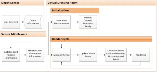
Figure 1.1: The overall virtual dressing framework
1.2
System Architecture
The framework operates in two distinct stages: modeling and simulation. The modeling stage consists of preparing the avatar and cloth meshes for the sim-ulation. The base low-detail avatar meshes, a male and a female, are ac-quired from online sources [6, 7], rigged with a skeleton, and painted with ma-terials and textures. The base apparel meshes are also acquired from online sources [8, 9, 10, 11, 12, 13]. They are aligned with the avatar meshes, painted, and their physical properties are specified. After the models are ready for simula-tion, they are exported in appropriate file formats to be loaded by the simulation stage.
The simulation stage starts after a user is identified. It is initialized by per-forming user body measurements and scaling the avatar and apparel meshes ac-cordingly. The render cycle starts with fetching the user skeletal joint informa-tion from the depth sensor. The virtual avatar and the static apparel meshes are updated by applying the acquired joint orientations. The collision spheres that coincide with the skeleton joints are also updated during this process. The dynamic apparel meshes are updated with new positions and orientations and the collision data and the updated topology information are transferred from the physics environment to the virtual environment, followed by rendering. The
overall virtual dressing framework is shown in Figure 1.1.
1.3
Organization of the Thesis
The thesis is organized as follows. Chapter 2, we give related work on virtual fitting rooms and depth sensors. Chapter 3 describes the human and cloth mod-eling for virtual fitting room. Chapter 4 focuses on the animation techniques along with various optimizations for a realistic experience. Chapter 5 discusses the physics engine and cloth simulation process. Chapter 6 deals with the cloth resizing process for a customized fitting experience. The experiments, perfor-mance qualities and results are presented in 7. Chapter 8 outlines the thesis and shows the future direction of this research. Appendix A describes the game engine that provides the boilerplate functions for our framework. Appendix B gives information about the depth sensor and its user tracking capabilities. A user interaction feature, depth-based hand tracking is explained in Appendix C.
Chapter 2
Related Work
Virtual fitting frameworks are complex systems composed of many modules. The related works on the major components of the used framework are summarized in this chapter, along with a general history of the field. The overall framework can be divided into three major modules: human body modeling and animation, motion capture systems and cloth modeling and simulation. Although these top-ics are connected in many ways, their foundations are distinct and should be discussed separately, followed by the discussion of the work on virtual fitting rooms.
2.1
Human Body Modeling And Animation
Although the human and apparel modeling both have foundations in 3D mesh creation, they require different traits and qualities. Human body modeling utilizes disciplines such as rigging and skinning, whereas apparel modeling is mostly based on physics simulations.
2.1.1
Human Body Modeling
As the humans are mostly the main characters in virtual worlds, various methods and techniques exist for human body models and animations. Determining the suitable one depends on the requirements of the application. Real-time applica-tions require a certain level of simplicity, as the simulation time cannot exceed the frame duration. Offline applications can utilize highly detailed models, looking much more realistic. The basis for both extremes however, is the same, which is a skeleton. The approach is starting with a connected set of rigid objects named as bones, continuing by adding layers of muscle, skin, hair and others, depend-ing on the required quality level. This is a very common modeldepend-ing technique used in computer graphics, which is called layered modeling technique [14]. The animation is achieved by rotating the bones, which is followed by upper layers. This technique also improves the reusability of the framework because the same animation sequence can be used for multiple body models with different detail levels utilizing the same base skeleton.
The articulated skeleton consists of a hierarchical structure of joints and limbs to model a human-like skeleton. Joints are the points that act as the origin of the respective local coordinate space. The limbs are the rigid segments that connect the joints in the hierarchy. Rotation in the local coordinate systems defined by the joints cause the rigid limbs to be rotated, creating the motion. The complexity of the model can be determined by the number of joints and the degrees of freedom (DOFs). The DOF is the number of independent parameters that define the configuration of a joint; a joint can rotate and translate in at most three orthogonal directions, hence, the maximum DOF a joint can have is six. Having the maximum number of DOFs in a human body model might seem like a good way to improve the realism, however this also increases the complexity of the structure, resulting in more mathematical operations. As most human-body joints can only rotate, not translate, assigning six DOFs to every joint is redundant. Furthermore, angular and axis constraints with certain joints (such as knee or elbow) further simplify the model while making it more realistic.
with hierarchical skeletons, Humanoid Animation (H-Anim) specification was de-veloped by Web3D Consortium [4]. Different levels of articulation are provided in X3D/VRML format, focusing specifically on humanoid objects rather than random articulated figures. H-Anim standard provides a common ground for applications to be classified depending on their humanoid animation complexity, mainly by the number of joints and DOFs.
2.1.2
Human Body Animation
Animating humanoid meshes is a complex and old subject of computer science, as there are many factors which contribute to the way humans move. The task gets even harder with the ability of the human eye to distinguish very minor unnatural motions. The first approaches on humanoid animation are stick figures, which have led to multi-layered high resolution meshes.
Stick figured animation dates back to 1970s, where the technology would limit the qualities of animation to one dimensional limbs [15]. With the advances in computer hardware, the details have improved and the complexities are in-creased. Surface models were the first improvement on top of the original stick figure animation. A surface or “skin”, which envelopes the articulated skeleton is introduced to the model. The translation of the surface varies depending on how the vertices are assigned to the bones. The process of assigning vertices to a specific joint or set of joints is called skinning. The quality of the animation depends on both the complexity of the skeleton as well as the skinning quality and technique.
The initial approach to the animation of enveloped surface was assigning weights to the individual polygons. However, this approach resulted in broken surfaces almost every frame. The first solution to this problem was introduced by Komatsu [16], where a continuous deformation function is used with respect to the joints. Another study introduced a new skinning process by assigning ver-tices to joints instead of polygons [17]. This simple difference allowed a polygon to be assigned to multiple bones, preventing two polygons from separating as the
common vertices would not get ripped.
Although assigning vertices instead of polygons to bones improved the realism significantly, it produced artifacts in extreme rotations. Inspired by the true nature of human skin and deformation, the new solution introduced assigning a vertex to multiple joints. Called linear blend skinning, this technique further improved the quality of character animations. However, it still was not sufficient with certain parts of body such as forearm and elbow, where the bone positioning and configuration are more complex than a single series of connected bones. An example of this situation can be seen in Figure 4.3. A single bone cannot imitate the twisting motion enabled by two parallel bones. Various solutions to this problem has been proposed, the proposed solution in this study is described in Section 4.4.3.
A new deformation technique called double quaternion skinning overcomes these artifacts without introducing additional time complexity [18], even improv-ing the performance. Quaternions, which are primarily used as a notation for ro-tations can also be used to define translations. Dual quaternions can be blended for rigid transformations and produce much more realistic results.
Another approach to fixing the extreme rotation situations was proposed by Kavan et al. [19], where the bones which could not produce realistic results would be split into child bones in runtime. This approach, although successfully cor-recting the otherwise present artifacts, required significantly more computational power and was not suitable for real-time applications.
2.2
Motion Capture Systems
2.2.1
Non-Optical Motion Capture Systems
Non-optical systems are based on mechanics, inertia [20] and magnetics [21]. Me-chanical systems were the earliest examples of motion capture systems and their
cumbersome hardware requirements make them hard to use. Inertial systems uti-lize inertia sensors to determine the global orientation of the body part they are attached to, which can later be converted to local orientations in post processing. Magnetic systems perform the same operation, except they do so by measuring the magnetic field emitted by the magnetic markers. Non-optical systems tend to deliver more accurate results than optical motion capture systems, although their hardware requirements and hardness to use are two major drawbacks.
2.2.2
Optical Motion Capture Systems
Optical systems are based on recording the target in action by one or more cameras. The most common approaches in optical motion capture systems utilize some sort of markers placed on key positions of the target. Markers can be passive [22] or active [23], depending on whether they just reflect the light or they emit light themselves. Regardless, their task is identical in both cases, providing the camera with the positional information of key parts of the body.
With the advances in computer processing power and camera technology, markerless motion capture systems have emerged [24]. Theobalt et al. have contributed to the markerless human motion capture systems subject with multi view video sequences [25, 26, 27]. Their framework utilizes 8 or more cameras placed on a circle around the target. They construct a volumetric visual hull by getting the intersection of extruded 2D silhouettes - which is called shape from silhouette technique [28, 29]. Using a set of cameras rather than a single camera is a remedy to the self-occlusion problem. After the visual hull of the user is ac-quired, the hull is segmented into body parts by fitting a pre-defined body model. Accurate as they are, these applications require immense computing power and are not suitable for real time applications.
The emergence of the consumer-level depth sensors at affordable costs cre-ated a new possibility for markerless motion capturing [30]. As the depth sensors operate in real time and the visual hull is the input rather than a processing prod-uct, the computation time for skeletal position estimation is considerably lower,
enabling real-time motion transferring from actors to virtual avatars. However, depth sensors suffer from the same disadvantage as single-camera systems, self occlusion, although this problem can be solved partially by utilizing multiple depth sensors [31]. Furthermore, the IR and TOF depth sensing technologies are not evolved enough yet to provide high resolution depth frames and produce quite a bit of noise, hence reducing the output motion quality. This problem is analyzed in depth by Khoshelham and Elberink [32] and concluded that the stan-dard deviation reaches two centimeters in a measuring distance of three meters. Matyunin et al. [33] attempted to improve the quality by filtering with additional information from the attached RGB camera.
2.3
Cloth Modeling and Simulation
A number of industries, mainly entertainment and apparel commerce, created a demand for rapid virtual apparel design and realistic simulation along with the advances in computer graphics. As every other physical phenomenon, gar-ment simulation is no simple task to perform in virtual worlds. To be able to create realistic render results for entertainment industry while keeping the physi-cal properties accurate requires very complex simulation frameworks and physics engines.
2.3.1
Cloth Design and Modeling
Garment design aims at creating meshes that look realistic. Furthermore, de-signing for virtual simulation environments require the garment to be suitable for physics simulation. The two approaches to creating 3D garment meshes are straightforward 3D design and combining 2D designed patches by “stitching”. However, the main distinction between garment design suites and techniques comes from the desired outcome, whether it is a production sample or a virtual model for simulation.
2.3.1.1 Production-oriented Design Systems
The design suites explained in this section focus on product creation and indus-trial usage of the apparel design, rather than virtual simulation. As the goals of two systems are different, other design techniques are used for simulation pur-poses. However, the underlying 2D and 3D design principles are quite similar. The initial approaches of 2D garment design consisted of two parts where each part has several steps [34]:
1. Parametric design-based pattern generation 2. Pattern alteration-based on grading techniques
A widely used CAD suite with this approach is Gerbert Technologies’ Ac-cuMark solution [35]. A major drawback of 2D garment design systems is the necessity of a certain level of expertise with pattern design, as the 2D patches are not easy to visualize for an inexperienced person. 3D garment design is the solution to this problem as the apparel can be modeled on virtual human models directly and then separated into multiple parts for production. In order to create realistic apparels, the underlying 3D human model must be realistic itself; best way is to obtain the mesh from a 3D full body scan. Assyst-Bullmer’s design software is an example of such CAD suites [36].
2.3.1.2 Simulation-oriented Design Systems
Simulation oriented design systems aim at creating garment meshes which are suitable for using in virtual environments, mainly in entertainment software such as video games, and recently, in virtual fitting rooms. The output of these suites must not be too complex to be simulated in real time, while being as realistic as possible.
One of the first physics-enabled 2D garment design systems was introduced by Yang et al. [37]. The suite included 2D design panels, deformable cloth modeling
and a human body model which could be used to simulate the designed apparel on. Chittaro and Corvaglio [38] aimed to develop a platform which would connect the textile industry with computer graphics and simulation world via defining an interchangeable format with VRML-based 3D meshes from 2D patterns. Turquin et al. [39] developed a sketch based interface for tailoring, dressing and simulating clothing pieces on virtual characters.
3D CAD systems suit simulation oriented design better than 2D by the nature of the general applications. The system developed by Bonte et al. [40] reverses the process defined in the previous examples, where the garment is designed in 3D and 2D patterns are generated from it. Garments are modeled on a mannequin to conform with the body characteristics of humans. The framework also includes a particle-based simulation feature. Cugini and Rizzi developed a framework [41] for the design of men apparel items with a 2D/3D hybrid approach using Autodesk Maya [42] for 3D modeling and simulation. A similar system was proposed by Durupınar and G¨ud¨ukbay [43] where the 3D garments would be created from 2D patterns and simulated using a mass-spring system.
The GPU company NVIDIA’s PhysX physics engine is one the best options for real-time physics simulation available [44]. An extension of this engine, APEX is a scalable dynamics framework with specialized physic based utilities such as destruction, particles, turbulence (fluids) and clothing [45]. The modeling exten-sion of this framework is available as an extenexten-sion for 3dsMax [46] and Maya [42] design suites. The extensions provide an interface which are aimed at creating an artist-oriented environment as possible, abstracting all the programming work. As the PhysX engine is optimized for NVIDIA GPUs, the easiness of the APEX along with its performance make it one of the best options for real-time clothing design-and-simulation framework.
With the advances in virtual try on systems, various frameworks for apparel design solely for the use with such environments emerged. The state of these frameworks are discussed in Section 2.4 along with virtual fitting room frame-works.
2.3.2
Garment Simulation
Garment simulation is mainly deforming an apparel mesh in a way which feels natural to the eye. It also includes collision detection and support for tearing be-havior. The nature of the garment simulation depends on the used modeling ap-proach. Two common garment modeling approaches are geometrical models [47] and physics-based models.
2.3.2.1 Geometric Garment Modeling
Geometric models do not take the physical properties such as stiffness and stretch-ing into account. Instead, the apparel is modeled as a collection of cables and hy-perbolic cosine curves, Weil added the stiffness factor as a distance constraint [47]. As the physical properties of clothes are omitted or not accurate, geometric mod-els do not work well with dynamic modmod-els as well as they do with stationary renders [47].
2.3.2.2 Physical Garment Modeling
Physical approaches model the cloth as systems of springs-masses or particles, or as a continuous flexible material to be solved as a elasticity problem. The spring-mass system is first presented by Haumann and Parent [48], which converts each vertex into a point mass and converts each edge into a spring. The simulation is attained by solving the mass equations. Further improvements on spring-mass systems include different sets of springs for orthogonal axes and distance constraints to achieve more garment-like simulations [49]. The NVIDIA PhysX engine utilizes an enhanced spring-mass system for its cloth solver [50].
Terzopoulos et al. [51] presented elastically deformable models based on con-tinuum mechanics and differential geometry. Another concon-tinuum-based approach that sacrifices accuracy for performance by focusing on numerical solutions was
described by Baraff and Witkin [52]. Elasticity solutions rely on energy interac-tions between the particles and achieve a solution by minimizing the total energy stored within the whole mesh.
2.4
Virtual Fitting Rooms
Virtual fitting rooms have been a research subject for more than a decade. Pro-topsaltou et al. [53] developed an Internet-based approach for virtual fitting rooms, although it was not real time and required marker-based motion capture systems for animation. Zhang et al. [54] used a multi-camera system utilizing shell fitting space (SFS) [29] techniques to build a real time intelligent fitting room.
Advances in time-of-flight technology made depth sensors available at consumer-level prices with better performance. This prompted a wave of re-search based on depth sensors in various fields, such as rehabilitation [55], indoor modeling [56], and medicine [57]. Another topic that attracted significant atten-tion from both researchers and companies is real-time virtual fitting rooms [58]. Giovanni et al. [59] developed a virtual try-on system utilizing a calibrated set of Kinect and high definition cameras, while comparing the two state-of-the-art depth sensing software development kits (SDKs)-OpenNI [60] and Kinect for Windows SDK [61]. While most frameworks utilize garment meshes with physics simulation [1, 2], another intriguing approach is using a pre-recorded apparel im-age database, from which the imim-ages are superpositioned onto the RGB video of the user [62, 63].
A key purpose of both virtual and real fitting rooms is giving the customer the look and feel of a cloth with a specific size on the user’s body, so the user can choose the appropriate size for him. Embedding the feature of matching cloth sizes with users requires capturing the users’ body dimensions. More advanced frameworks even construct virtual avatars with input from only one depth sen-sor [64, 65]. On the other hand, despite these works provide higher detail avatars
and keener measurements, which might be more suitable for made-to-measure type of framework, the process requires too much time to work with a real-time ‘fixed-size try-on’ virtual fitting room application where simple body height and width measurements are sufficient. These applications require a faster ap-proach along with a specialized garment design framework such as the works of Yasseen et al. [66] or Meng et al. [58]. There are also notable studies for made-to-measure technologies for online clothing stores [67], shape control techniques for automatic resizing of apparel products [68], modeling a 3D garment on a 3D human model by 2D sketches [69], and garment pattern design using 3D body scan data [70]. A recent study [71] shows that such applications are well-received by public and have potential commercial uses.
Chapter 3
Human and Cloth Modeling
The simulation software utilizes 3D models as the main displayed components. Since the quality of the models are a significant factor in the overall quality of the simulation, they must be prepared specifically for the purposes of the application, with attention to details. Two distinct sets of 3D meshes are required in general for the simulation:
• A cloth mesh to be processed by the embedded physics engine.
• A full body human mesh to act as an avatar for the simulated cloth mesh.
3.1
Human Avatar
After taking the complexity of both 3D CAD programs and the human body it-self into consideration, designing a complete full human body mesh is deemed to be a laborious and inessential task. Through researching various digital sources, evaluating the quality and cost of various potential candidate meshes, a female [6] model and a male model [7] are elected, due to their realistic appearance, accu-rate proportions and fine details. For the purpose of improving the realism of the simulation, details are introduced to the base model with the Blender CAD software [5].
3.1.1
Rigging
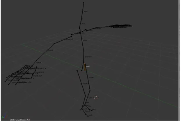
Animating a 3D mesh requires skinning, which is moving the vertices with respect to a bone on a skeleton. Because the base models have no skinning or material properties, they require custom rigging and painting. For the purposes of this research a manual rigging and painting would be preferred, in order to be able to integrate the model easily into the software. The rigging is performed in Blender [5], where the base human skeleton is provided, detailed in H-ANIM2 level with a simplified spine (Figure 3.1).
Figure 3.1: The rigging base skeleton.
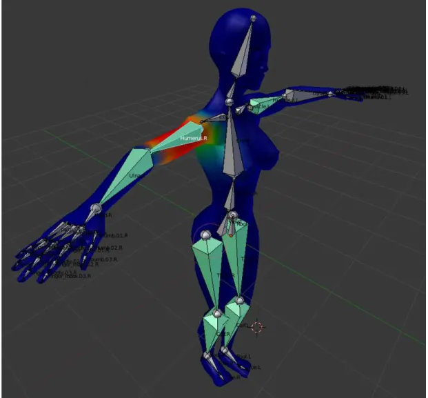
Prior to rigging, the skeleton needs to be in perfect alignment with the mesh. After modifying the initial bone positions, the vertex groups are assigned to the bones with proper weights (Figure 3.2). After assigning every vertex to the appropriate bones, there are no cracked surfaces with motions which are natural for humans. In the end, the models are exported in OGRE .mesh format along with the skeleton it used.
Figure 3.2: The vertex weights for the Humerus.R bone.
3.1.2
Material Properties
The base models come with no material properties. In order to improve the realism of the model, texturing/painting tasks for various parts of the body are performed. These parts include the general skin, hair, eyes and lips (Figure 3.3). Other additions include accessories such as hair sticks and earrings to achieve more realistic results.
Figure 3.3: Detailed appearance of the face.
3.2
Cloth Mesh
As one of the major pieces of this study is accurate cloth simulation, accurately modeled cloth meshes which are suitable for simulation for required. After a thorough research through a variety of available models, a set of base apparel meshes for both male and female models are selected [8, 9, 10, 11, 12, 13]. The models vary in detail and quality, all of them are optimized and enhanced for the framework.
3.2.1
Body Positioning and Splitting the Dress Mesh
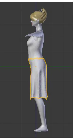
For a successful animation and simulation of the dress on a human avatar, both meshes must be in proportion with each other and properly aligned. The required modifications to the meshes are performed in Blender(Figure 3.4). The initial approach is to include all the vertices of the clothing mesh in the simulation. However, after various attempts to simulate all vertices on the dress mesh, this approach failed to achieve a realistic looking result because of two reasons:
• Whole meshes contain too many vertices, the dress mesh for instance con-sists of 4088 vertices. The simulation Runs in real-time, however the topog-raphy of the mesh is not appropriate for the physics engine because of the very large number of vertices in the cloth. It shifted from a fabric structure to more of a jelly form, over stretching and tearing with its own weight. • The friction necessary to keep the dress on the human avatar’s shoulders
is not sufficient enough to keep the dress on the avatar. The dress keeps sliding, stretching and acting unnaturally. The design of the used physics engine is not appropriate for this approach.
In order to overcome these problems, we split the dress mesh into two parts and utilize different animation techniques for each.
• The static part, which should be attached to the body and not affected by the wind, is modeled as a static mesh with skinning, like the human avatar. It is animated with the same transformations as the human avatar, matching its position and staying on the body perfectly.
• The dynamic part is the part to be simulated, affected by inertia, wind and other factors. Their attachment line is just above the waist of the human avatar, which is pinpointed through try-and-error experiments with other locations (Figure 3.4). Keeping the line very low resulted in both unnatural collisions and the cloth being too rigid. Keeping it too high brought out the problems in the first approach. With its current setting, the dress mesh is animated naturally on the virtual avatar.
Figure 3.4: The dress, positioned on the body, along with the upper-part of the skeleton. In this shot, the dynamic part is highlighted with orange border.
Chapter 4
Animation
The animation in the system consists of moving the virtual avatar and the cloth mesh in a realistic manner, with the addition of physical simulaton of the apparel meshes. This chapter focuses on the animation of human avatar and the static cloth meshes, the physical animation is explained in Chapter 5.
The rigged human body mesh ready to be animated is exported from Blender in Ogre XML format. The XML files are converted to binary skeleton and mesh files by the OgreXML serializer and imported natively into the software. Prior to animation, the bones are set up to be updated by the data from depth sensor. Afterwards, they are updated with the orientation data.
4.1
Initialization
Animatable meshes are loaded and maintained via the custom SkeletalMesh class, which is the middleware between Ogre skeletal animating system and the input from Kinect sensor. An instance of the SkeletalMesh class is initialized with a mesh file. After the mesh is loaded with the skeleton data, the bone list is iterated through, given the initial orientation uniquely for each animatable bone with the Kinect sensor.
The animatable bones are set to be manually controlled and set to their initial orientations. The lower part of the body inherits orientations as they are filtered for footskating and use different orientation mechanisms. The upper part of the body is rotated in global space. The bones are set to their initial state, to be reset at every frame and updated with new orientations. The non-animated bones are left to be automatically controlled in order to keep them aligned with their parent bones.
4.2
Animation
Every frame, the orientation information from the bones are extracted in quater-nion form, along with the confidence of the sensor in that orientation. If the confidence is less than 0.5 over 1, the bones are left as they were in the previ-ous frame to avoid unnatural movements. The root bone is translated in local space at the end to simulate the translation above rotation. This technique is used with the static parts of the apparel meshes as well. The linear weighted skin blending [72] is used in order to simulate deformation on the characters skin. The effects of four bones with different weights are combined linearly to change the positions and normal of vertices.
Algorithm 1 is executed during the pre-render cycle. The bone orientations are set to be ready for animation, deformation and rendering. At every render cycle, update Skeleton function is called, which automatically fetches the coordinates from the Kinect and sets up the skeleton for vertex blending.
Algorithm 2 is executed prior to rendering, to update the vertices of the skin. The vertex blending function is where the deformation actually occurs. Every vertex is assigned to at most four different bones. In order to speed up the defor-mation process, the transfordefor-mation matrices for the corresponding matrices are collapsed into one. Collapsing is simply weighted addition of the four weighting matrices for a vertex.
Algorithm 1: Bone transformation algorithm
1 function transformBone(bone)
Input: A bone and the corresponding orientation matrix from Kinect Output: The same bone with updated orientation
2 qI = initial orientation of bone 3 qN = relative orientation
4 qK = 3 × 3 Orientation matrix from Kinect 5 if kinectconfidence > 0.5 then
6 qQ = toQuaternion(qK) 7 qN = toLocalSpace(qQ) 8 q = qN × qI
9 bone.orientation = q.normalise() 10 if user is new then
11 ptorso.initialize() /* Initialize torso position */ 12
13 foreach bone do
14 if boneorientation is new then 15 transformBone(bone) 16 skeleton.needsUpdate()
matrices, the following matrix operations are performed. Four vertices are pro-cessed together in order to fully utilize the parallel matrix multiplication features. Let us take the weighted matrix for vertex i:
Mi = mi 00 mi01 mi02 mi03 mi10 mi11 mi12 mi13 mi20 mi21 mi22 mi23 0 0 0 1 (4.1)
It should be noted that this matrix is a linear combination of four linear transformation matrices from four weighting bones; hence, the 3rd row is by default [0 0 0 1]. We also have the initial positions for the four vertices as [pi
xpiy piz1].3rd value, which is one is not included in the vertex buffer and it will
not be taken into account with the calculations. In order to generate an efficient SIMD process, we perform 4×3 dot product calculations in each instruction. Dot products are commanded in the machine language, which makes it more
efficient compared to higher level matrix calculations. To compute the simulated x coordinates for four vertices, we combine the first rows of all collapsed matrices into a 4 × 4 matrix and transpose it:
MT = m000 m100 m200 m300 m001 m101 m201 m301 m0 02 m102 m202 m302 m0 03 m103 m203 m303 (4.2)
We construct a position matrix of size 4 × 3 with the positions of all vertices:
PT = p0 x p1x p2x p3x p0 y p1y p2y p3y p0z p1z p2z p3z (4.3)
Next, the matrices MT and PT are multiplied in a row-by-row fashion and
summed together to calculate the x-coordinate displacements of four vertices: dx= MT 0× PT 0+ MT 1× PT 1MT 2× PT 2+ MT 3 (4.4)
The result vector dx is a 4 × 1 vector, which has the post-blended vertex
x-coordinates: [Px0 Px1 Px2 Px3]. The same procedure is applied to the normal of a vertex. Process continues with the next set of four vertices.
4.3
Interaction Between the Body and Cloth
The movements of the user are passed on the pieces of cloth separately. Non simulated parts of the clothes are the ones which do not get separated from the body most of the time. Most parts of our clothes usually stick to the body and experience the same deformation as our skin. In order to increase performance and get better results, detailed simulation on these parts are not run, instead
they are deformed the same as the remained of human body. For instance, in the full-body dress mesh, the part above the waist has a skeleton similar to the body and the information from the Kinect is passed on to this portion as well. It is treated as a part of the actual avatar.
The movements of the body are transferred into the simulated section of the cloth through transformation, collision and inertia. The fixed vertices are transformed to match the remainder of the cloth. The transformation is done on the rendering level, the physx world experiences no difference in transformation manner. This process keeps the cloth aligned with the rest of the visible world. The colliding body is updated and collided with the cloth. The colliding body consists of 16 spheres and the capsules connecting the spheres. The details of the colliding body is explained in Section 3.1. This process keeps the cloth out of the avatar’s way. The Inertia of transformations is passed onto the simulated cloth, increasing the realism. The passed on inertia comes from the rotation and the transformation of the root bone of the human skeleton. With this process, although there is no actual transformation in the physics world, the resulting inertia effects are visible on the cloth itself.
4.4
Motion Filtering
Application of the raw data from the sensor causes unnatural movements due to the noise in the sensor input, self-occlusions of the body and inadequate IK solvers. In order to present a more realistic avatar animation, a series of filters and constraints are applied to the sensor data.
4.4.1
Position Filtering
The most severe disruption of the self-occlusion problem takes place in the joint position acquisition. There is no possible way of acquiring the correct position of a limb when the sensor has no vision of it. However, the way humans move
their limbs under normal conditions follow certain principles and trends, which can be used to estimate the locations of occluded body parts. The nature of these motions, demonstrating traits similar to seasonal behavior, makes them suitable for applying a variety of filters [73]. The framework utilizes the Holt-Winters double exponential smoothing [74, 75] as it comes with the middleware, easy to use and delivers good quality results with acceptable latency for the purposes of this application.
4.4.2
Rotation Filtering and Constraints
The joint orientations are acquired from the sensor middleware directly, however the data is not smooth. Although the middleware enforces certain constraints (such as allowing only pitch rotations on ulna), there are often significant gaps in the estimated angles that produce unnatural tremor-like movements on the avatar. Furthermore, there is no filtering of unnatural rotations that take place when an occluded body part is estimated to be in a wrong location.
The inferior quality of the orientation data is improved in two stages: applying another set of constraints on the joint data based on the natural limits of human bones, followed by an asymptotic smoothing of the joint angles to prevent the effect of gaps in the angles (see Figure 4.1).
4.4.3
Bone Splitting
The lower sections of human limbs contain two parallel bones allowing the twisting rotation on the hands and feet. The configurations of bones allow all portions of the lower limbs follow the bones in pitch and roll rotations, although the effect of yaw rotation decreases as it gets closer to the mid-section joint (elbow or knee). This effect is not possible to achieve with a single bone fore-arm representation, as specified in the highest level of detail in the H-ANIM standard [4], using unified weights (same for all types of rotations, transformations and scaling) and linear skinning. On the other hand, applying a different set of weights for each possible transformation, rotation or scaling requires additional space and time, which can be considered redundant as it is not going to be used in most parts of the skeleton and surface mesh; thus, it is not implemented in most of the popular rendering engines. This problem is addressed by Kavan et al. [19], proposing a method of introducing additional blending bones to simulate non-linear skinning. However, this approach is not suitable for a real-time application with previously unknown motions.
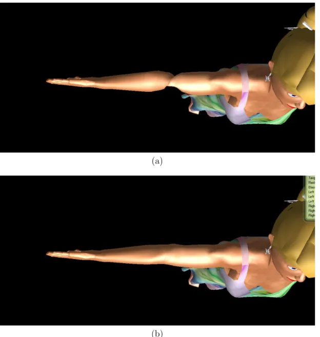
Since the only problematic bones for this particular case are the upper limbs, this problem is solved using a novel approach by introducing an additional bone connected in series for the upper limbs. The ulna bones are split halfway and the lower sections are labeled as ulna-extension. The vertex weights in the corre-sponding sections are divided linearly among two sections, as seen in Figure 4.2. During runtime, the filtered local rotation of the upper limb bones are sepa-rated into two distinct rotations, one containing the yaw and the other containing pitch and roll rotations, which are applied to the extension bone and the original bone, respectively. With proper weights, the rotation of the users arm is trans-ferred to the virtual avatar naturally without introducing any artifacts. As seen in Figure 4.3, the vertices on the forearm twist in a more natural way resembling the real motion.
(a)
(b)
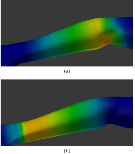
Figure 4.2: The vertex weights for (a) the upper ulna and (b) the lower ulna bone (weight increases from blue to yellow).
(a)
(b)
Figure 4.3: Comparison of a -90◦ yaw rotation on the forearm with: (a) single and (b) double-boned skinning.
4.5
Handling the Foot Skating Problem
The virtual model is animated by changing bone orientations and root bone po-sition. If the orientations and root position are applied to the bones respectively, the feet of the character appear to be floating on the ground that deteriorates the realism. This problem, known as footskating, is not limited to depth sensor appli-cations. It shows up in motion-capture-based animation systems and solved in a reasonable way with approaches, such as Kovar et al. [76] and Ikemoto et al. [77]. However, these methods rely on some sort of preprocessing or supervised learn-ing, which is not suitable for our system, as the motion is captured and applied im real time. Hence, a solution that does not require a training process is needed for such applications. Mankyu and Choi [78] propose a similar method that does not require training for real-time depth sensor applications. Their approach is adopted into our framework to overcome the footskating problem. However, it re-quires additional filters and constraints in order to be usable in our framework. It is assumed that one foot is always on the ground; otherwise, artifacts may occur, for example, if the user attempts jumping. The footskating handling algorithm consists of two parts: constraint checking and adaptation (cf. Algorithm 3) and joint angle determination and application (cf. Algorithm 4). The whole algorithm consists of the following four steps.
1. Determine which foot is constrained by checking speed and location thresh-olds. The thresholds are changed adaptively in order to compensate for different sensor and user placements.
2. Place the constrained foot at its last recorded position and solve the inverse kinematics problem to determine the orientations of the hip and knee joints. Solving an inverse kinematic problem is no trivial task. There are various numerical and analytical methods for inverse kinematic problems and many implementations focusing on each. We use the IKAN library by University of Pennsylvania [79], which uses the approach described in [80].
3. Check if the foot coincides with its intended position after the inverse kine-matic orientations are applied to the bones. If there is a positional mis-match, relocate the root joint to complete alignment.
4. Smooth the joint orientation difference in order to avoid jumps from frame to frame. This is especially important when the constraint switches, as the source of the orientations are different in two cases and they do not always overlap. Smoothing parameters are optimized using trial and error; they are not viable for adaptive nature. Smoothing also helps to overcome the self-occlusion and data-noisiness.
Joint smoothing consists of interpolating between frames, especially when there is a significant change in orientations, which would normally cause a non-continuous animation. Old joint orientations are always recorded in the global coordinate system and updated everyframe. After we get the new orientation from the new frame, we calculate the quaternion that would rotate the old orientation to the new one:
Qd= Qnew× Q−1old (4.5)
When we compute the delta quaternion, we get its axis-angle representation. Because we are interested in rotating the joint partially, we build up a new quater-nion with the same axis and a fraction of the same angle. The fraction varies with whether the constraint is switched recently.
Qd= Quaternion((x, y, z), α)
Q∗d= Quaternion((x, y, z), α/k)
(4.6) The fractional rotations are then applied to the joints to get a smoother move-ment. Other implicit operations include coordinate system transformations, as we are working with three different coordinate systems: Global-Render Coordinate System, Local-Render Coordinate System, and IKAN Coordinate System.
Algorithm 2: Mesh update algorithm called at every frame 1 function prepareBlendMatrices(mesh) 2 foreach bone do 3 bone.applyScale() 4 bone.applyTransform() 5 bone.applyOrientation() 6 i = 0 7 foreach bone do 8 m[i] = bone.getTransformationMatrix 4 × 4 9 i + +
/* Index map contains the bone pointers for every vertex */
10
11 mapIndex=mesh.getIndexMap() i = 0
/* Blend matrices are pointers to the individual bone matrices */
12
13 foreach indexSet in mapIndex do 14 mb[i] = indexSet[i] + m i + + 15 return mb
16 function vertexBlend(mb)
17 pos=*mesh.positions /* Pointer to position matrix */
18
19 norm=*mesh.normals /* Pointer to normal matrix */ 20
21 bi =*mesh.blendIndices /* Pointer to blend index matrix */ 22
23 bw =*mesh.blendWeights /* Pointer to blend weight matrix */
24
25 foreach 4 vertices in pos do 26 foreach vertex in 4 vertices do
27 m[1, 2, 3, 4] = mb[bi[vertex]] /* Weighting Bones */ 28
29 mc[j] = collapseMatrix(m, bw[vertex])(i) 30 pos[4vertex] = mc× pos[4vertex]
norm[4vertex] = mc× norm[4vertex] 31 if skeleton needs update then
32 mb = prepareBlendMatrices(skeleton.mesh) 33 vertexBlend (mb)
Algorithm 3: Constrained foot determination
1 if isFirstFrame then 2 if pylef t < pyright then 3 constrained = left 4 ythreshold= pyleft 5 else 6 constrained = right 7 ythreshold= pyright 8 if constrainedislef t then
/* Check if constraints still hold */
9 if pyleft > ythreshold and vleft > vthreshold then
/* Foot is not constrained anymore, check other foot */
10 if pyright > ythreshold and vright > vthreshold then
/* Neither foot are constrained */
11 updateThresholds() /* Thresholds should be updated */
restart
12 else /* Right foot is constrained, feet switched */ 13 constrained=right
14 recordRightFootPosition() 15 constraintSwitched = True 16 else
/* Check if constraints still hold */
17 if pyright > ythreshold and vright > vthreshold then
/* Foot is not constrained anymore, check other foot */
18 if pyleft > ythreshold and vleft > vthreshold then
/* Neither foot are constrained */
19 updateThresholds() /* Thresholds should be updated */ restart
20 else /* Left foot is constrained, feet switched */ 21 constrained = left
22 recordRightFootPosition() 23 constraintSwitched = True
Algorithm 4: Foot skating filtering
1 checkFootConstraints() /* Check which foot is constrained */
pfootconstrained= getRecordedF ootP osition()
2 targetik = pfootconstrained− phipconstrained
/* Get the rotation quaternions for constrained hip and knee */
3 qhip, qknee = solveIkan(constrained, targetik) 4 hipconstrained.rotate(qhip)
5 footconstrained.rotate(qhip)
6 pfootnew= calculateForwardKinematics()
/* Calculate the root displacement vector */
7 droot = pfootconstrained - pfootnew 8 root.translate(droot)
Chapter 5
Cloth Simulation
Rendering physically accurate apparel meshes is the goal of the physics com-ponent of the framework. Because the construction of a real-time high quality physics engine that supports collision detection is a study subject on its own, The Nvidia PhysX engine is utilized as the physics solver [50] in the simula-tion software. The quality of the simulasimula-tion depends on a number of different steps; the model preparation, physics environment initialization and the real-time simulation including numerical solution of the spring mass sytems and collision handling.
5.1
Model Setup
The mesh to be simulated is the dynamic part of the modeled dresses that contains vertices in the order of thousands. It is aligned precisely with the static part and the human body to be simulated realistically. The PhysX framework requires vertex and topology information delivered separately and manually, instead of a binary file or an automatic parser. For this purpose, a custom Wavefront object file (OBJ) parser is implemented to acquire the information exported from a modeling suite, and feed the data into the physics engine.
Other than the vertex and topology information, an inverse weight property needs to be specified for every vertex. This information could be embedded into the wavefront object as a second set of texture coordinates. On the other hand, this method adds too much data to the file, which brings extra computational overhead. Therefore, the vertex weight information is embedded into the model by specifying the material properties separately for vertex groups with different weights. The vertices that have a non-zero inverse weight have the suffix “Free” attached to their material properties. The vertices are selected manually and their material properties are attached. The current simulation required only two sets of weights, which can be seen in Figure 5.1. After the weight information is implemented, the model is exported as a Wavefront object file (OBJ) along with the material file (MTL) and parsed into the software.
Figure 5.1: The fixed vertices of the cloth.
5.2
The Initialization
Following the parsing of the model from the object file, it is stored within the memory to be used in different frames. The object file is converted into the native mesh format for the rendering engine to be loaded and rendered. The process includes feeding the vertex, topology and material information into the
OGRE framework as submeshes, to be combined as a mesh. Prior to creating the simulated cloth, the PhysX engine needs to be initialized:
1. The foundation and SDK objects are created.
2. In order to implement the GPU solver for the cloth and collision, the PhysX engine needs to bind with the CUDA context to deliver the GPU tasks. The CUDA Context manager object is created and given to the SDK object. 3. Afterwards, the virtual floor and the environment are created with the
gravity specified as 9.8 m/s2.
After the initialization, the cloth is loaded with specific stiffness, stretch, damping, friction, inertia, bending, and collision parameters. These parameters are decided through numerous try-and-error experiments in order to acquire the most realistic simulation results. After creating the environment and the virtual cloth, the collision spheres are created, which is explained in Section 5.5.
5.3
The Animation
At each frame, the following steps are performed:
1. The passed time since the last frame is added to the counter.
2. The Kinect sensor is checked for new data. If the data is not new, next frame is called.
3. If there is an active user with the Kinect, the sensor middleware pointer is sent to the human body and the upper cloth SkeletalMesh objects to be updated. If there are none, the bones are reset to their initial state.
4. The upper body mesh and the human body mesh are updated. The details of the update process can be found in Section 4.2. This function returns the translation of the root node.
5. The returned vector from step 4 is used to translate the dynamic cloth handle. After the translation, the orientation is updated with the root bone orientation.
6. The colliding human capsules are updated with the human body bone ori-entation. The orientation and the position of the dynamic cloth handle is synchronized with the virtual cloth. This input automatically introduces the inertia effect on the cloth.
7. At the end, the cloth is simulated as follows:
(a) PhysX is ordered to start the simulation on the GPU. The details of the simulation algorithm are explained in Section 5.4.
(b) The vertex data is read from the output, and the vectors of the object file are updated, except the fixed mesh vertices. The reason for omit-ting the fixed vertices is to avoid unnatural bends and cracks on the fixed vertices.
(c) The updated object file vectors are transformed into the native mesh buffers, to be rendered.
The cloth simulation algorithm is based on the position-based dynamics, in-troduced by M¨uller et al. [81]. The main approach is to calculate the position of the particles from their previous positions and applying constraints on mutual distance and angle. The collision is also calculated as a force and applied to both particles. The approach is stable and efficient for real time applications. The dynamics are stable as long as the constraint solvers converge. When this crite-ria is not met, rendering anomalies occur, such as a vertex being pulled too far away from the cloth. The solution is parallelized by fibers, as Single Instruction Multiple Data (SIMD) process. With CUDA support, however, this is even par-allelized more with Single Instruction Multiple Thread (SIMT) processes, where each thread works on one fiber.
5.4
Numerical Solution
The position of a particle in the next time interval is acquired by performing explicit Euler integration over δt, where the velocity and the force are assumed to be constant during the interval. The pseudo code of the integration procedure is given in Algorithm 5.
Algorithm 5: Position-based dynamics solver
1 foreach vertices i do 2 initialize xi = x0i, vi = vi0, wi = 1/mi 3 while true do 4 foreach vertices i do 5 vi ← vi+ ∆twifext(xi) 6 dampVelocities(v1, . . . ., vN) 7 foreach vertices i do 8 pi ← xi+ ∆tvi 9 foreach vertices i do 10 generateCollisionConstraints(xi → pi) 11 while solverIterates do 12 projectConstraints(C1, . . . , CM +Mcoll, p1, . . . , pN) 13 foreach vertices i do 14 vi ← (pi− xi)/∆t 15 xi ← pi 16 velocityUpdate(v1, . . . , vN)
Algorithm 5 predicts the next position and velocity (lines 1-2), performs the corrections by solving the constraints (lines 3-12), updates the position and ve-locities accordingly (lines 13-15), adds damping to veve-locities (line 16). The key issue in the simulation is the position correction due to the constraints. Each vertex is moved either towards or away from each other, the distance is scaled by the inverse mass of the vertices. If a vertex position needs to be fixed, the inverse weight should be set to zero
5.4.1
Constraints, Fibers and Sets
In order to simulate the cloth, all constraints should be solved, which is achieved through linearizing the non-linear problem. This linearization results in a sparse matrix problem. Although the problem is solvable in real-time, performance is increased further by pivoting vertical and horizontal constraints, solving sepa-rately. The vertical and horizontal constraints are divided in the input sense by fibers and sets. Fibers represent independent sets of connected constraints and sets are non-overlapping fibers, which are solved in parallel. A fiber is either a horizontal, vertical or a diagonal line, and the set is the collection of parallel lines. These fibers and sets are generated for both shear and stretch constraints by the PhysX mesh cooker, which auto-generates the fibers and sets from a given mesh topology.
5.4.2
Set Solvers
There are two possible solvers to apply on fiber block (set) which come with PhysX:
• The Gauss-Seidel solver continues along the fiber after completing a con-straint solution and updating the results. This solver is easy to tweak and use, has low-cost for iteration, however the convergence factor is low due to sequential update, which results in a stretchy cloth.
• Semi-implicit solver factorizes the tri-diagonal system with LDLT and solves the overall system. This method preserves momentum since it is not sequen-tial and converges ten times more than Gauss-Seidel solver. However, the matrices can be ill conditioned, which requires special treatment, iteration cost is higher and tweaking is more difficult.
In order to get the best performance from these solvers, they are applied on different sets, taking advantage of parallel implementation. The Gauss-Seidel solver is used for horizontal stretch fibers and the shear fibers, which do not