AN INVESTIGATION OF PUNCHING AND
MECHANICAL PROPERTIES OF ROLLED AM60
AND AZ61 MAGNESIUM ALLOYS
2020
PhD THESIS
MECHANICAL ENGINEERING
SHOKRI SALEH M KHALIFA
AN INVESTIGATION OF PUNCHING AND MECHANICAL PROPERTIES OF ROLLED AM60 AND AZ61 MAGNESIUM ALLOYS
SHOKRI SALEH M KHALIFA
T.C
Karabuk University Institute of Graduate Programs Department of Mechanical Engineering
Prepared as PhD Thesis
Assist. Prof. Dr. Harun ÇUĞ
KARABUK June 2020
ii
I certify that in my opinion the thesis submitted by Shokri Saleh M KHALIFA titled “AN INVESTIGATION OF PUNCHING AND MECHANICAL PROPERTIES OF ROLLED AM60 AND AZ61 MAGNESIUM ALLOYS” is fully adequate in scope and in quality as a thesis for the degree of PhD.
Assist.Prof. Dr. Harun ÇUĞ ...
Thesis Advisor, Department of Mechanical Engineering
APPROVAL
This thesis is accepted by the examining committee with a unanimous vote in the Department of Mechanical Engineering as a PhD thesis. Jun 17, 2020
Examining Committee Members (Institutions) Signature
Chairman : Prof.Dr. Hayrettin AHLATCI (KBU) ...
Member : Assoc.Prof.Dr. YUNUS TÜREN (KBU) ...
Member : Assoc.Prof.Dr. Hakan DİLİPAK (GU) ...
Member : Assoc.Prof.Dr. Hakan GÜRÜN (GU) ...
Member : Assist.Prof.Dr. Harun ÇUĞ (KBU) ...
The degree of PhD by the thesis submitted is approved by the Administrative Board of the Institute of Graduate Programs, Karabuk University.
Prof. Dr. Hasan SOLMAZ ...
iii
“I declare that all the information within this thesis has been gathered and presented in accordance with academic regulations and ethical principles and I have according to the requirements of these regulations and principles cited all those which do not originate in this work as well.”
iv ABSTRACT
PhD. Thesis
AN INVESTIGATION OF PUNCHING AND MECHANICAL PROPERTIES OF ROLLED AM60 AND AZ61 MAGNESIUM ALLOYS
SHOKRI SALEH M KHALIFA
Karabük University Institute of Graduate Programs The Department of Mechanical Engineering
Thesis Advisor:
Assist. Prof. Dr. HARUN CUG June 2020, 57 pages
In this study, the low pressure die casting method was used to produce AZ61 and AM60 Mg alloys following the hot rolling with two rolling speed and hot extrusion were applied at similar deformation rate. Light optical (LOM) and Scanning electron microscopy (SEM) was utilized to show the twins, dynamic recrystallization (DRXs) and secondary phases. The enhancement of mechanical properties obtained by micro-hardness and tensile tests were supported with the microstructural and pole figure analysis. In the industry, punching is required for the manufactured parts, and therefore the magnesium alloys that are manufactured (AM60 and AZ61) require strength to complete the punching process. an experimental study was carried out to examine the effect of different punch type on blanking force. The strength of mg alloys AM60 and AZ61 as casting and as two speed of rolling 2.5 rpm and 7.5 rpm treatment has been examined by using shearing force with same thickness 3mm. The effect of the perforated cutting type on forces required for cutting / punching has been realized on magnesium alloys used in the industry. Experiments were studied using three different cutting types, 0 °, R and 16 °. The results of the experiment showed that the AM60 alloy was stronger than AZ61, and the results also showed that the 16º hole type
v
performs the breaking process at the lowest strength. necessary paste was used when using R type perforations for sheet production.
Key words: AZ61, AM60, Hot rolling, Microstructure, Mechanical Properties, Punching.
vi ÖZET
Doktora Tezi
HADDELENMİŞ AM60 VE AZ61 MAGNEZYUM ALAŞIMLARININ ZIMBA İLE DELME VE MEKANİK ÖZELLİKLERİNİN İNCELENMESİ
Shokri Saleh M. KHALIFA
Karabük Üniversitesi Lisansüstü Eğitim Enstitüsü Makine Mühendisliği Anabilim Dalı
Tez Danışmanı:
Dr. Öğretim Üyesi Harun ÇUĞ Haziran 2020, 57 sayfa
Bu çalışmada, AZ61 ve AM60 magnezyum (Mg) alaşımları düşük basınçlı döküm yöntemi ile üretilmiştir. Üretilen Mg alaşımları iki farklı haddeleme hızında sıcak haddeleme ile %75 deformasyon sonucunda 3 mm kalınlığında levha haline getirilmiştir. Ayrıca döküm sonrasında Mg alaşımlarına yine %75 deformasyon oranında sıcak ekstrüzyon işlemi uygulanmıştır. Işık optik (LOM) ve Taramalı elektron mikroskobu (SEM), ikizleri, dinamik yeniden kristalleşmeyi (DRX'ler) göstermek için kullanılmıştır. Mikro sertlik ve çekme testleri ile elde edilen mekanik özelliklerin iyileştirilmesi, mikroyapısal ve pole figür analizleri ile desteklenmiştir. Endüstride imal edilen parçaların kullanılabilmesi için bir imal işlemine tabi tutulması gerekliliğinden yola çıkarak sıcak haddeleme sonrasında elde edilen 3 mm kalınlığındaki Mg levhalarına delme (zımbalama) işlemi uygulanmıştır. Deneyde düz uçlu, içbükey formlu ve 16 ° açılı olmak üzere 3 farklı zımba kullanılmıştır. Kullanılan zımba tipinin kesme kuvveti üzerindeki etkisi incelenmiştir. Deneyler sırasında kesme
vii
kuvvetlerini belirlemek için bir yük hücresi kullanılmıştır. Delme deney sonuçları AM60 alaşımının AZ61'e göre kesmeye karşı daha dirençli olduğunu göstermiştir. En düşük kesme kuvveti 16 ° açılı zımba ile elde edilmiştir. Ayrıca, delme işlemleri için düz uçlu zımbaların ve kesme işlemleri için içbükey formlu zımbaların kullanılmasının, parçaların kullanım amacına göre daha uygun olduğu bulunmuştur.
Anahtar kelimeler: AZ61, AM60, Sıcak haddeleme, Mikroyapı, Mekanik Özellikler, Delme.
viii
ACKNOWLEDGMENT
The name of Almighty Allah, the praise is to the God. The work was carried out in the Faculty of Engineering at Karabük University, under the supervision of Assist.Prof.Dr. Harun ÇUĞ, whom I would like to thank sincerely for his encouragement, guidance and advice throughout experimental work and for his constructive criticism during the preparation of this thesis.
I am also particularly grateful to Assoc.Prof.Dr. Hakan GÜRÜN, Prof.Dr. Hayrettin AHLATCI and Assoc.Prof.Dr. Yunus TÜREN for carrying out some experiment, and for their advice and support. I would like to thank also all staff in the department foretheir help.
In the end, I thank my family and parents who were very supportive and patient until I completed this important stage of my life.
ix CONTENTS Page APPROVAL ... ii ABSTRACT ... iv ÖZET... vi ACKNOWLEDGMENT ... viii CONTENTS ... ix
LIST OF FIGURES... xii
LIST OF TABLES ... xiv
CHAPTER 1... 1
INTRODUCTION... 1
CHAPTER 2... 3
LITERATURE REVIEW... 3
2.1. PHYSICAL & MECHANICAL PROPERTIES OF MAGNESIUM ... 4
2.2 MAGNESIUM ALLOYS... 4
2.2.1. AZ61 ... 5
2.2.2. AM60 ... 5
2.3. MAGNESIUM CASTING ... 5
2.3.1. Rolling ... 6
2.4.MG-AL BASED ALLOY ... 6
2.5. MAGNESIUM AND ITS ALLOYS APPLICATIONS ... 7
2.6. CASTING OF MAGNESIUM ALLOYS ... 9
2.6.1. High Pressure Die Casting ... 9
2.6.2. Low Pressure Die Casting ... 10
CHAPTER 3... 12
PUNCHING ... 12
x
Page
3.2. EFFECT OF PUNCH-DIE CLEARANCE ... 13
3.3. DIFFERENT AREAS OF THE PART EDGE... 14
3.4. THE EFFECT OF PUNCH TYPE ... 15
3.5. THE BLANKING PROCESS ... 15
CHAPTER 4... 17 EXPERIMENTAL STUDIES ... 17 4.1. MATERIALS ... 17 4.1.1. Casting ... 17 4.1.2. Hot Rolling ... 20 4.2. MICROSTRUCTURE INVESTIGATIONS ... 23 4.2.1. Sample preparation ... 23
4.2.2. Optical and Scanning Electron Microscope Images ... 23
4.2.3. X-ray Diffraction (XRD) and X-ray Fluorescence (XRF) Analysis ... 24
4.2.4. Grain Size and Twinning Fraction Analysis ... 25
4.3. MECHANICAL TESTS... 25 4.3.1. Hardness Tests ... 25 4.3.2. Tensile Tests ... 26 4.4. Punching Test ... 27 CHAPTER 5... 29 RESULTS ... 29 5.1. MICROSTRUCTURE... 29 5.2. GRAIN SIZE ... 32 5.3. TEXTURE ... 33 5.4. HARDNESS TEST ... 33 5.5. TENSILE TEST ... 34 5.6. FRACTURE ... 37
5.7. EFFECTS OF PUNCH TYPE ON SHEARING FORCE OF MAGNESIUM ALLOYS ... 38
5.7.1. Effect Of Shear Forces... 39
xi
Page
CHAPTER 6... 45
DISCUSSION ... 45
6.1. TEXTURE AND MECHANICAL PROPERTIES OF PLASTICALLY DEFORMED AZ61 AND AM60... 45
CHAPTER 7... 47
CONCLUSIONS ... 47
REFERENCES ... 49
xii
LIST OF FIGURES
Page
Figure 2.1. Schematic representation of a conventional rolling system ... 6
Figure 2.2. Binary phase diagram of the Mg-Al ... 7
Figure 2.3. Magnesium auto parts ... 8
Figure 2.4. Magnesium electronic parts ... 8
Figure 2.5. High pressure casting equipment ... 9
Figure 2.6. A schematic diagram of a typical low-pressure die ... 11
Figure 3.1. Different blank and scrap for blanking and piercing ... 13
Figure 3.2. Blanking and piercing parts ... 14
Figure 3.3. Zones of the edge ... 14
Figure 3.4. Type of punch ... 15
Figure 3.5. Schematic of the blanking tool setup ... 16
Figure 4.1. a) Diagram and b) Photo of a low pressure die casting furnace ... 18
Figure 4.2. Casting samples ... 20
Figure 4.3. Rolling sample of magnesium alloys AZ61 ... 21
Figure 4.4. Extrusion device used in the experiment ... 22
Figure 4.5. Extrusion device used in the experiment ... 22
Figure 4.6. a) Nikon Epiphot 200 Model optical light microscope, b) Carl Zeiss Ultra Plus Gemini Fesem brand scanning electron microscope (SEM), c) Nikon Shuttle Pix P-400R Model stereo microscope ... 24
Figure 4.7. Rigaku Ultra IV model X-ray device (XRD) ... 25
Figure 4.8. Shimadzu HMV2 microhardness tester for hardness measurements ... 26
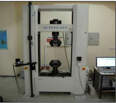
Figure 4.9. Shimadzu AG-IS 50 kN tensile tester for tensile testing ... 26
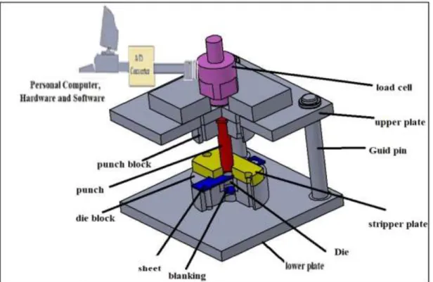
Figure 4.10. Schematic overview of the experimental set-up ... 27
Figure 4.11. Type of punches used in the experiments and forms of the falling parts ... 28
Figure 5.1. The SEM images of as-cast ... 30
Figure 5.2. The LOM images ... 30
Figure 5.3. The SEM-EDS results... 31
xiii
Page
Figure 5.5. Hardness results of investigated alloys ... 34
Figure 5.6. Tensile test specimens of hot rolled specimens ... 35
Figure 5.7. Extruded tensile test sample ... 36
Figure 5.8. Tensile graph of investigated alloys as engineering stress (MPa) ... 37
Figure 5.9. Tensile graph of investigated alloys as engineering strain (cm/cm) ... 37
Figure 5.10. Fracture surface of rolled ... 38
Figure 5.11. Effects of punch type on shearing force of magnesium alloys ... 39
Figure 5.12. Blanking forces according to the punch type and material ... 40
Figure 5.13. Punch penetration depth vs shearing force (displayed in separate graphs) ... 41
Figure 5.14. Depth zones for different Mg alloys gained from using of flat ended punch ... 42
Figure 5.15. Depth zones for different Mg alloys gained from using of concave formed punch ... 42
Figure 5.16. Punching simulation with Punch 0° (Flat) and name of parts ... 43
Figure 5.17. A) Blanking cross section, B) Blanking cutting surface and C) Sheet hole cutting surface... 43
Figure 5.18. Stereo microscope images taken from cross section and cutting surface of samples after punching using flat ended punch (0°) ... 44
xiv
LIST OF TABLES
Page
Table 2.1. Physical properties of pure magnesium ... 4
Table 4.1. Casting conditions ... 19
Table 4.2. Raw materials used for production (% by weight) ... 19
Table 4.3. Produced alloy groups (wt%) ... 19
Table 4.4. Rolling parameters ... 21
Table 5.1. EDS results of investigated alloys ... 31
Table 5.2. Average grain size of investigated samples ... 31
Table 5.3. Hardness Vickers results of investigated alloys ... 34
Table 5.4. Tensile test results of investigated alloys ... 36
1 CHAPTER 1
INTRODUCTION
Magnesium alloys have strong durability; therefore, they play an important role in the transportation field, and also due to the properties of specific strength and light weight (strength / density) [1]. It is used in alloying. Magnesium also has high thermal conductivity, high dimensional stability, good electromagnetic protection, high damping, good workability and easy recycling [2]. These properties make Mg alloys attractive in many industries such as automotive, computer, aerospace, mobile phones, sports equipment. It is also used in light weight industries[3]. In addition, efforts have been accelerated in recent years to use energy resources more efficiently. In this context, the automotive industry is also working towards lighter vehicles in order to reduce fuel consumption [4] . Today, in parallel with the advancement of technology, the desired properties of materials also change. Corrosion resistance, resistance and adaptation to the environment can be changed positively by the materials being subjected to various processes. Although their mechanical properties are relatively low in pure form, these properties are particularly noticeable when alloyed with aluminum (Al), zinc (Zn) and manganese (Mn) [5]. The most common alloys are Al-Mn (AM50, Alloys such as AM60 and Al-Zn (AZ31, AZ61, AZ91) alloys. Other Mg alloys with good creep resistance at high temperatures are made up of rare elements [6]. For magnesium, especially Al, Zn and Mn, especially with earth metals and trace amounts of alloy elements Si, Y, Ca, Sr, Ba, Sb, Sn, Pb and Bi by increasing the mechanical properties of performance it is increasing [7]. Mg-Al-Zn (AZ91) alloys are mostly used for the casting of automobile parts and the castability of this alloy is quite good. Some studies have focused on increasing strength, hardness particularly by addition Zn, Mn, Al and rare earth elements to magnesium and its alloys [8]. Low-pressure die casting (LPDC) is the process whereby the metal rises into the mold cavity against gravity using pressurized gas, and high-pressure die casting (HPDC) is the process in which the metal is forced into the mold cavity at a high speed and pressure [9].
2
In this study, AZ61 and AM60 alloys have been produced by using an electric resistance furnace. The magnesium alloys manufactured were rolled by using two different speeds, 2.5 m/min and 7.5 m/min, respectively. The sheet thickness was decreased to 3mm thick. Effects of the material and rolling conditions on the blanking process were experimentally studied depending on the punch tip type and change of blanking forces. Three punches which have different tip forms were used. Force measurements were obtained by using a load cell during the experiments.
3 CHAPTER 2
LITERATURE REVIEW
To develop mg alloys and improve the properties of mg alloy must be adding different metals such as Aluminum, zinc, zirconium, Rare Earth elements etc. [10]. Scientists and researchers have a been interest in the possibility of use magnesium because of its high strength to weight ratio, but cannot be used directly as mentioned above , to overcome these drawbacks of magnesium must be add some materials to improve its properties[11]. Improve of magnesium properties to use in some applications have been studied by a lot of scientists and researchers and they got that, when aluminum is added to the magnesium alloy, it affects and gets better casting properties, develop corrosion resistance properties. An increase in yield strength of mg alloys[12]. Magnesium alloys such as Az91 has been made where main composition of 9% Aluminum 1% zinc and 0.3% manganese. And investigated that AZ91 has high strength to weight ratio[14]. Anther researchers have studied twin roll strip casting of AZ61 and the effect of casting conditions and rolling parameters on surface aspects and microstructure of the rolled[15].
Dr. Gürün and his collages studied the experimental examination of effects of punch angle and clearance on shearing force and estimation of shearing force using fuzzy logic comparing with this study where their result as following the effects of punch shear angle and clearance on the force required for blanking/piercing were examined on a grade of steel broadly used in the manufacturing industry, DC01. Experiments were carried out using five different punch shear angles, namely 0°, 2°, 4°, 8°, and 16°. Six matrices with varying clearance rates (0.4%t,0.5%t, 0.6%t, 0.7%t, 0.8%t, and 0.9%t) were used in this study, and these clearances were altered by modular matrices on the die. Which is related with this study as following:
4
Yu’an Chen and his collages (Effect of Zn on microstructure and mechanical property of Mg–3Sn–1Al alloys) The microstructure and mechanical properties of the Mg– 3Sn–xZn–1Al alloy were investigated. The microstructure of alloy consists of α-Mg and Mg2Sn phases. The grain size decreased gradually with Zn content increases, and
the amount of Mg2Sn particles increased markedly. The as-extruded Mg–Sn–Zn–Al
alloy exhibits excellent comprehensive mechanical properties, an ultimate tensile strength of 290 MPa, a yield strength of 184 MPa and an elongation of 12.2% at room temperature.
2.1. PHYSICAL & MECHANICAL PROPERTIES OF MAGNESIUM
Magnesium was first isolated by Sir Humphry Davy, an English chemist, through the electrolysis of a mixture of magnesium oxide (MgO) and mercuric oxide (HgO) in 1808. Now, magnesium can be extracted from the mineral’s dolomite (CaCO3·MgCO3) and carnallite (KCl·MgCl2·6H2O) but is most often obtained from seawater. Every cubic kilometer of seawater contains about 1.3 billion kilograms of magnesium. Magnesium is the lightest of used metals[16]. Table 1 shows physical properties of pure magnesium.
Table 2.1. Physical properties of pure magnesium. Physical properties Density (g/cm3) Melting Point (°C) Specific Heat
(Cal/g°C) conductivity Electrical
(%IACS) Thermal Conductivity (W/mK) Pure Magnesium 1.74 650 0.24 39 167 2.2 MAGNESIUM ALLOYS
Pure magnesium is usually used with the alloyed for engineering applications. Alloying is used to develop the formability of magnesium for both wrought and cast products. Zinc and aluminum are the most common alloying elements. Manganese, silicon and rare earth metals are other alloying elements that have significant influence on the properties of alloy [17]. Addition of alloy elements to mg to develop mechanical properties is common for instance Aluminum (Al) Increases tensile
5
strength and hardness, Improves castability [18]. Zinc (Zn) Increases tensile strength and hardness Refine grain structure [19]. Manganese (Mn) Increases corrosion resistance with reducing the influence of iron and Increases yield strength [20], Silicon (Si) Increases molten metal viscosity Improves creep resistance forms Mg2Si particles
Reduces the corrosion resistance [21], Rare Earth Metals Reduces the freezing rang Increases hardness [22].
2.2.1. AZ61
AZ61 series magnesium alloys are among the most used alloys among magnesium alloys due to their good casting properties and good mechanical properties. It is frequently used in the aviation and aerospace industry and the automotive industry. Microstructure of AZ 61 alloys generally grain boundaries within a-mg main matrix It consists of eutectic and intermetallic phases running along.
2.2.2. AM60
AM series alloys, one of the Mg alloys, are used especially in the production of steering wheel, wheel, automobile seat frame due to their high toughness and energy absorption properties. AM60 alloys have good elongation and impact resistance. These alloys; They have good castability, good mechanical properties and corrosion resistance. However, these alloys have low creep resistance at temperatures above 120 °C. The microstructure of the AM60 alloy generally consists of phases a-mg and Mg17Al12
[24-26].
2.3. MAGNESIUM CASTING
To obtain magnesium products with desired shapes beside casting can be use thermomechanical processes, to do Mg fabrication the technic that used are extrusion and rolling. Since at low temperature, magnesium shows low formability, these thermomechanical processing are usually implemented at high temperature (300 °C to 500 °C) [27].
6 2.3.1. Rolling
A conventional rolling device used in this study consists of two parallel rollers rotating at the same speed. In the normal direction (ND), where the length of the material increases in the rolling direction (RD), the material thickness has decreased [28]. Increasing width in the transverse direction (TD) was considered insignificant.
Figure 2.1. Schematic representation of a conventional rolling system [29]. Traditional rolling was implementation on a 12 mm thick plate. For the first trial, two passes were carried out at 300 °C with a 40% discount with preheating.
2.4.MG-AL BASED ALLOY
Using alloy aluminum with magnesium to improve mechanical and chemical properties such as strength and corrosion resistance. A maximum solid solubility of aluminum in magnesium is 12.6 wt% at (437 oC ) (Figure 1) and then its solubility reduces to around 2% at room temperature. Hence, after a precipitation hardening treatment, an incoherent [30].
7
Figrue 2.2. Binary phase diagram of the Mg-Al [31]. 2.5. MAGNESIUM AND ITS ALLOYS APPLICATIONS
Since it has low strength and toughness values, it is used by alloy. Magnesium also has high dimensional stability, good electromagnetic protection, and easy recycling [32]. The first use of magnesium alloys is considered in military applications. Nowadays, especially in the automotive sector, it is spreading in areas that require less energy consumption and lower gas emissions [32]. Magnesium alloys in the automotive sector date back to the 1920s. The first app is engine presses for Indy 500 race car in America. In Germany in 1937 magnesium presses produced about 4 million units. The other crankcase Mg was manufactured in 1931 by the general engine. Around 1970, applications of air-cooled gearboxes and engines were used in the automotive sector. Increased engine power and increased temperature led to the use of water-cooled engines instead of air-cooled engines, thereby reducing the use of Mg components. However, applications such as the Mg seat frame, passenger door and steering frame have been produced by brands such as Mercedes and BMW since 1990. It is also an ideal alloy for all portable electronic devices [33]. These properties are appreciated by Mg alloys in many industries such as automotive, computer, aerospace, mobile phones, sports equipment. It is also used as an implant material for low weight and adaptation to metabolism [33]. In addition, efforts have been accelerated in recent years to use
8
energy resources more efficiently. In this context, the automotive industry is also working towards lighter vehicles in order to reduce fuel consumption [34].
Figrue 2.3. Magnesium auto parts, a) fuel tank protector, b) gearbox c) steering frame d) gearbox e) seat frame and f) passenger door frame[33].
Figrue 2.4. Magnesium electronic parts a) saw b) camera c) laptop and d) mobile phone[34].
9 2.6. CASTING OF MAGNESIUM ALLOYS
2.6.1. High Pressure Die Casting
In recent years interest in magnesium alloys has increased as it has entered the automotive components industry such as steering wheel, dashboards, seat tires, door frames and powertrain components [35]. The important manufacturing process is high pressure casting for cast Mg alloy components used for a large number of applications. However, high-pressure casting (HPDC) Mg-alloys contain significant amounts of microporosity [36]. Microporosity and other casting defects appear to negatively affect the mechanical properties of cast Mg alloys and may result in significant variability in their mechanical properties [37]. Although microporosity amount appears to negatively affect the tensile ductility of HPDC Mg-alloys, attempts to establish quantitative correlations between the average porosity in bulk microstructure and fracture-sensitive properties such as strength or ductility have often failed [38].
Figrue 2.5. High pressure casting equipment.
10 2.6.2. Low Pressure Die Casting
Low pressure casting has been developed to eliminate hand ladders of hot metal. This process also uses metal molds to produce castings, but the molten metal is pressurized to obtain a faster or better controlled filling of the mold. The process uses pressures up to 7 MPa for special products such as automotive wheels, but the pressure typically used is below 0.5 MPa [39]. Low pressure casting is widely used for larger and non-critical parts. High quality castings of aluminum alloys are usually produced by this process, as well as magnesium and other low melting alloys [40].
2.6.2.1. Advantages of low pressure die casting
Below are shown the advantages of low pressure die casting.
• Very good strength values
• Greater use of material, without the need for feeders, • Good dimensional precision,
• The whole process well adapted to automation, • Less complicated machine and die technology. 2.6.2.2. Disadvantages of low pressure die casting
Below are shown the disadvantages of low pressure die casting.
• Slower launch cycles • Minimum wall thickness • Approx. 3 mm (in die)
11
12 CHAPTER 3
PUNCHING
3.1. PUNCHING APPLICATION FOR MG ALLOYS
Magnesium has an important role in engineering and industrial applications due to their light weight, where Density of the magnesium is (1.8 g/cm3) Less than aluminum
density (2.7g / cm3) [44]. Several studies have shown that casting is still the main
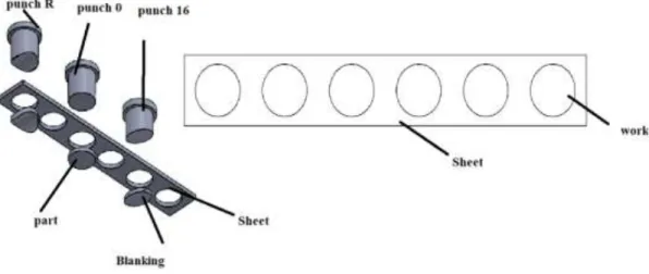
production method to produce Mg alloys where the dominant manufacturing process for magnesium components is casting, representing more than 95% of structural applications of magnesium, However, the low pressure die casting method still very limited [39]. The enhancing performance in engineering and industrial applications is criticale therefore, reducing the weight of construction materials is nessasery [45]. magnesium can be utilized as an application in aerospace industry. Magnesium alloys are made with a mixture of magnesium and other metals such as aluminum, manganese and copper [46]. In industrial and engineering applications, sheet metal forming using large-scale punching and cutting dies in manufacturing, the conditions under which punching and cutting dies are processed are influenced by the mechanical properties of sheet metal [47]. Previous studies have indicated that the most important factors that affect the shearing force and quality of parts are clearance and punch angle. The punch angle greatly decreased the required suppression/punch force. To improve the mechanical properties of sheet metal parts, surface quality, and dimensional precision, it is important to focus on the shapes and positions of the die and punch. [48]. In this study punching is required for the manufactured parts, and therefore the magnesium alloys that are manufactured (AM60 and AZ61) require strength to complete the punching process. an experimental study was carried out to examine the effect of different punch type on blanking force. The strength of mg alloys AM60 and AZ61 as casting and as two speed of rolling 2.5 rpm and 7.5 rpm treatment has been examined by using shearing force with same thickness 3mm. The influence of punch shear-type
13
on the forces required for blanking/piercing were carried out on magnesium alloys used in the industry. Experiments were studied using
Figure 3.1. Different blank and scrap for blanking and piercing.
Three different punch shear types, namely 0°, R, and 16°. The results of the experiment show that AM60 alloy stronger than AZ61, the result also obtained results of Experiments study show that punch type 16º carried out blanking with the lowest force, using of punch type 0º when blanking required while punch type R used for sheet production.
3.2. EFFECT OF PUNCH-DIE CLEARANCE
Several studies indicate that shear strength is not significantly affected by the value of clearance. However, it affects the quality of the product and therefore 1 to 3 mm thickness one clearance of 0.07 mm was used to give the best quality, for the sheet metal industry requires a range of different processes [49] in the manufacture of sheet metal parts are very commonly used of Sheet metal forming processes like blanking, stamping and bending, Metal shearing is used for Blanking and piercing in order to cut the incoming sheet material as necessary. The bleaching process means cutting a hole in a sheet metal and interested in the disc that is cut, while the drilling process means that when the sheet metal that now has a hole goes through the scrap if you are interested in a disc, the scrap is a sheet metal that has a hole through it [50]. as shown in the diagram in Fig. 3.2.
14
Figure 3.2. Blanking and piercing parts [50]. 3.3. DIFFERENT AREAS OF THE PART EDGE
The shear edge of material influenced by different parameters such as the punch corner radius and therefore made several zones based on the method of material that has occurred,[50]. In general, it is preferred to have large shear zone and smaller burr the zones and deformation modes of the blanked part edge are given as follows and in fig (3.3). Rollover zone (zr): caused by plastic material deformation, Shear zone (zs): smooth and shiny area created during material shearing, Fracture zone rough surface, created after the material cracks, Burr zone (zb) is happened by plastic deformation, Depth of crack penetration (Dcp) is angle of fracture zone depends mainly on clearance [51].
15 3.4. THE EFFECT OF PUNCH TYPE
Recently some studies investigated the Experimental examination of the effects of punching angle and clearance on cutting force and estimation of cutting force. The test results indicate that shear forces can be reduced by 80% when using a 16 ° punch angle [52]. Punch clearance was found not to have as significant an effect as punch angle on cutting force. Although the reduction of cutting forces using angled punches is a practical and cost-effective method, it leads to deformations in the perforated part. As the punching angle increased, the amount of deformation increased. However, no deformation was observed on the strip. This leads to the conclusion that angled punches may be more suitable for drilling dies.
Experiments were carried out using Three type of separate punches 0°, R and 16°were used in the experiments with a diameter of 20 mm were prepared using wire EDM.
Figure 3.4. Type of punch.
3.5. THE BLANKING PROCESS
During blanking, the separating plate (which is also the blank support) holds the sheet material by applying a certain separating force. The sheet material between the punch and the die undergoes a very high deformation and cuts as the punch penetrates the sheet material with speed. The extraction plate removes the bullet from the punch during the upward movement of the punch as shown in (figure 3.4).
16
To obtain the best product and the minimum force required to blanking/piercing the magnesium alloys, three types of punching machine were used with the best type of clearance selected according to the previous studies [49]. Blanking force measurements were performed using a load cell. A 240 kN the load cell is attached to the die to measure the suppression / puncture forces in effect during the experiments.
The experimental results were transferred to the digital medium by the load cell, the data card, the amplifier and the data visualization software. To improve the precision of the measurements obtained, the signals generated by the load cell were strengthened by using an amplifier. An analog to digital converter used to transmit the amplified signal to a computer. The die set and load cell are presented in Fig. 3.5. Optical microscopy (OM) and scanning electron microscopy (SEM) were used to analyze the microstructures.
17 CHAPTER 4
EXPERIMENTAL STUDIES
4.1. MATERIALS
In this study, microstructure, texture and mechanical properties of AM60 and AZ61 magnesium master alloys produced by casting were investigated after casting, rolling and extrusion processes. In addition, the cutting forces and cutting surfaces of the same master alloys with different punch geometries of the samples produced by casting and rolling at different speeds were examined.
AZ61 and AM60 Mg alloys is product with casting method. Low pressure die casting system (LPDC) as shown in Fig 4.1 is used in this study. After casting the casting samples put in furnace for homogenization heat treatment. Then rolling and extrusion manufacturing method is done for product this study samples.
4.1.1. Casting
The raw materials used for production are given in Table 4.1. Pure Mg, Al pure, pure Zn alloys from Turkey gauges are supplied from China. For the production, a special low-pressure gravity die casting method was used (Figure 4.1) and the casting conditions given in Table 5.2 were complied with. Pure Mg was first introduced into the stainless-steel crucible. After reaching a temperature of 775 ° C, after a waiting period of 1-hour, pure Al and gauge alloys were added to the ladle. Meanwhile, the molten metal in the crucible was continuously stirred. The final alloy was added to the pure Zn crucible and after 10 min stirring the molten metal was injected into stainless steel metal molds having a temperature of 350 ° C under 2-3 atm pressure.
18
Figure 4.1. a) Diagram and b) Photo of a low pressure die casting furnace.
a)
19
Table 4.1. Casting conditions. Protective gas Melting temperature (°C) Mold temperature (°C) travel allowance temperature (°C) Casting gas pressure Argon 775 350 350 2-3
Table 4.2. Raw materials used for production (% by weight).
Raw material Mg Al Zn Mn
Pure Mg 99.9% - - -
Pure Al - 99.9% - -
Pure Zn - - 99.9% -
Mg-Mn Master alloy 90% - - 10%
The chemical contents of the produced alloys are given in Table 4.3. Rigaku ZSX Primus II device belonging to XRF laboratory of Karabük University Iron and Steel Institute was used for chemical analysis.
Table 4.3. Produced alloy groups (wt%).
Alloys Al Zn Mn Mg
AZ61 5,95 1,05 0,0032 Bal.
20
Figrue 4.2. Casting samples.
4.1.2. Hot Rolling
After casting, billets with dimensions of 120x36x12 mm were heat treated for homogenization at 400 °C for 24 hours. In order to prevent metal oxidation during homogenization and homogeneous temperature distribution, the materials were embedded in sand. Homogenized materials with parameters in Table 4.4.'de hot rolling process was applied. Here, 15% (total 11 passes) and 30% (total 5 passes) section contraction was applied to each pass. Interpass materials were stored in an oven at 400 °C for 5 minutes. Billets with initial thickness of 12 mm total 75%
21
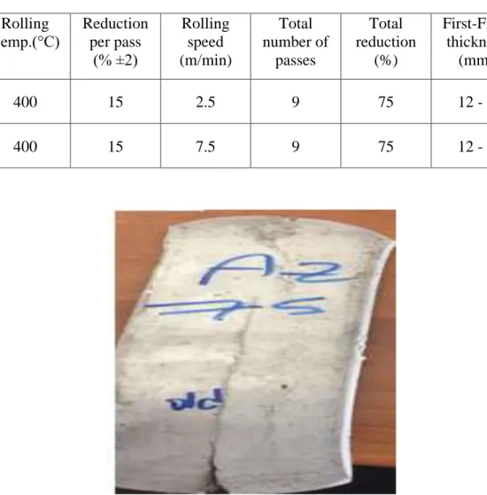
Table 4.4 Rolling parameters.
Figrue 4.3. Rolling sample of magnesium alloys AZ61.
4.1.3 Extrusion
Casting sample is machining with rolling min stirring the molten metal was injected into stainless steel metal molds having a temperature of 350 °C under 2-3 atm pressure, then are sintered in a furnace (MAGMA THERM MT-137-B2) at 700 °C for 24 hours, after being sintered in 24 hours, using a specially designed extrusion die at 450 mm to concentrate 4 pieces of different samples. samples of the diameter were extrude to a diameter of 8 mm. Figure 4.4 shows the extrusion device used in the experiment.[68]
Rolling Temp.(°C) Reduction per pass (% ±2) Rolling speed (m/min) Total number of passes Total reduction (%) First-Final thickness (mm) 400 15 2.5 9 75 12 - 3 400 15 7.5 9 75 12 - 3
22
Figure 4. 4. Extrusion device used in the experiment.
In the first samples obtained after the extrusion process, as seen in Figure 4.5, deflection problem was observed [68].
23
4.2. MICROSTRUCTURE INVESTIGATIONS
4.2.1. Sample preparation
The cast-iron, homogenized and post-extrusion microstructure of the produced alloys was prepared with an acetic-picral (70ml ethanol, 5ml acetic acid, 5g picric acid and 10ml pure water) etch. Sanding process with 600, 800, 1000, 1200, 2500 sanding sheets and polishing process with 1µm diamond suspension and 1µm felt were carried out before etching process.
4.2.2. Optical and Scanning Electron Microscope Images
The castings, homogenized and post-rolled microstructure examinations of the alloys produced were carried out on Nikon Eclipse MA200 optical microscope in Karabük University (KBU) Iron and Steel Institute metallurgy laboratory and Carl Zeiss Ultra Plus Gemini Fesem model scanning electron microscope in SEM laboratory. In addition, energy distribution spectrometer (EDS) studies were performed on the same SEM device.
24
Figure 4.6. a) Nikon Epiphot 200 Model optical light microscope, b) Carl Zeiss Ultra Plus Gemini Fesem brand scanning electron microscope (SEM), c) Nikon Shuttle Pix P-400R Model stereo microscope.
4.2.3. X-ray Diffraction (XRD) and X-ray Fluorescence (XRF) Analysis
Rigaku brand ZSX Primus II model XRF and Ultima IV model XRD devices were used in the XRD-XRF laboratory of KBU Iron and Steel Institute, respectively, to determine the chemical contents and phases-textures of the produced alloys. XRD graphs were taken in the range of 15-90 ° on a copper-targeted XRD device. Missing pole figure measurements were obtained from (0002), (10-10), (10-11) and (10-12) peaks and the maximum texture strength and distributions were determined using the MTEX toolbox.
25
Figure 4.7. Rigaku Ultra IV model X-ray device (XRD). 4.2.4. Grain Size and Twinning Fraction Analysis
Grain size analyzes were calculated according to ASTM E112 standard from 200X magnification optical microscope images. SEM images with 500X magnification were used to calculate the twinning fraction and point calculation was performed according to ASTM E562-02 standard.
4.3. MECHANICAL TESTS
4.3.1. Hardness Tests
The hardness tests were carried out in the Micro and Macro Hardness Measurement Laboratory of KBU Iron and Steel Institute in accordance with TS-EN-ISO 6506-1 standard under a load of 187 mm kg. At least 3 measurements were taken from each material.
26
Figure 4.8. Shimadzu HMV2 microhardness tester for hardness measurements. 4.3.2. Tensile Tests
Tensile tests were carried out in the static laboratory of KBU Iron and Steel Institute using MTS branded 100kN Servo Hydraulic Dynamic Tester at room temperature with a speed of 1 mm / sec according to ASTM A370-12a standard. At least 3 tests were taken from each material.
27 4.4. Punching Test
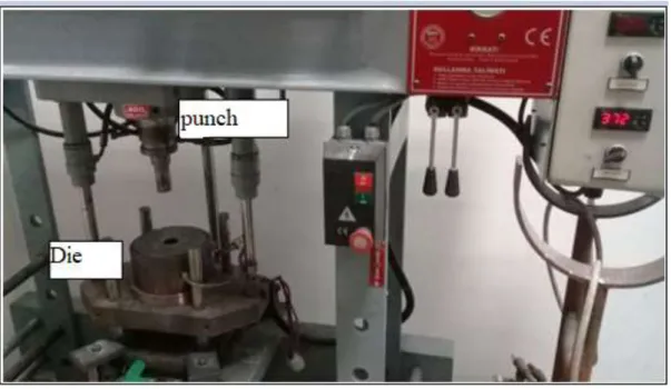
After preparing the samples used in this study, their length of 20 cm width and 30 mm thickness of 3 mm was introduced into the punching system as shown in figure 4.6 and the measurements of the suppression force were performed using a load cell that has a capacity of 120 kN and a data reading speed of 10,000 data / sec. The data reading speed was adjusted to 2000 data / sec. The experimental results were transferred to the digital medium by the load cell, the data card, the amplifier and the data visualization software. To improve the precision of the measurements obtained, the signals generated by the load cell were strengthened by using an amplifier. An analog to digital converter used to transmit the amplified signal to a computer. The experimental setup is presented in Fig. 4.10.
Figure 4.10.Schematic overview of the experimental set-up.
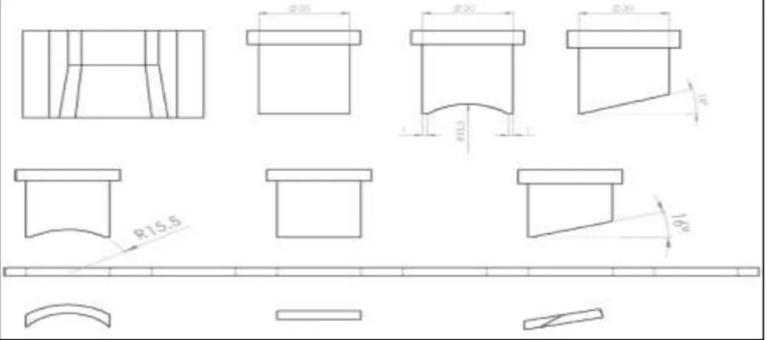
Three types of punches which have different tip forms were used in the experiments. Punches were machined with a diameter of 20 mm. Tip forms of the punches were assigned as flat ended (0°), concave formed (R), and angled (16°) and cut by using a
28
wire EDM. Type of punches used in the experiments and form of the falling parts are given in Fig 4.11.
29 CHAPTER 5
RESULTS
5.1.
MICROSTRUCTUREThe microstructure of the investigated alloys is shown in Fig.5.1 (SEM) and Fig 5.2 (LOM) as-cast and rolled - extruded, respectively. The as-cast images illustrate that AZ61 consists of globular shaped secondary phases which distributing at grain boundaries and in the matrix (see Fig5.1a). Moreover, the as-cast of AM60 alloy includes bigger sized and complex shaped secondary phases in the matrix and continuously distributed ones at grain boundaries (see Fig 5.2b). Hot rolling deformation initiates equiaxed grains, twins, and DRXs on the microstructure. As seen Fig 5.3(a-b), AZ61RS2.5 and AZ61 RS7.5 alloys have equiaxed grains however the twins more occupied on microstructure for AZ61 RS7.5 than AZ61 RS2.5. Further, AM60 RS2.5 and AM60 RS7.5 alloys include equiaxed grains which especially introduced as DRXs however the continuous DRXs more placed on AM60RS7.5 than AM60 RS2.5 (see Fig 5.3(c-d). In addition, the extruded AZ61 and AM60 alloys consist of equiaxed grains where the DRXs more presented at AZ61 than AM60 (see Fig 5.3e-f). The EDS results show that both AZ61 R2.5 and AZ61 RS7.5 Mg alloys include Mg-Al-Zn and Mg17Al12 secondary phases also AZ61 RS7.5 have Al8Mn5
type one (see Fig 5.3(a-b) and Table 5.1). Moreover, AM60 RS2.5 consist of Mg17Al12
and Al8Mn5 type secondary phases however AM60 RS7.5 have just Al8Mn5 (see Fig
5.3(c-d) and Table 5.1). Further, EDS results of extruded AZ61 don’t illustrate any secondary phases on the other hand AM60 contain Al8Mn5 type (see Fig.5.3(f) and Table 5.1).
30
Figure 5.1. The SEM images of as-cast a) AZ61 and b)AM60 alloys.
Figure 5.2. The LOM images of a-c) hot rolled AZ61 at b-d) hot rolled AM60 at e) extruded AZ and f)extruded AM.
a)
b)
31
Figure 5. 3. The SEM-EDS results of a-c) hot rolled AZ61 at b-d) hot rolled AM60 at e) extruded AZ and f)extruded AM60.
32
Table 5. 1. EDS results of investigated alloys.
Method Alloy In Fig. As Shaped Mg Al Mn Zn
Rol le d AZ61 RS 2.5 3a 60,31 35,68 0,00 4,01 AZ61 RS 2.5 3a 42,19 38,96 0,00 18,84 AZ61 RS7.5 3b 81,35 14,37 1,17 3,12 AZ61 RS7.5 3b 51,23 26,69 2,83 16,25 AZ61 RS7.5 3b 4,64 53,65 41,65 0,05 AM60 RS2.5 3c 4,58 52,40 41,42 1,60 AM60 RS2.5 3c 83,01 10,96 2,73 3,30 AM75 3d 2,94 53,18 42,63 1,24 E xt rude d AM60 3f 45,84 39,49 12,24 2,44 5.2. GRAIN SIZE
As seen Table (5.2), the average grain size of the samples is similar for rolled AM25 and AM75 and extruded AZ61 and AM60. However, the rolled AZ25 and AZ75 samples present different grain size wherein the AZ75 have highest one (see Table 4).
Table 5.2. Average grain size of investigated samples.
Method Alloy Average grain
size (µm) Rol le d AZ61 RS 2.5 46,8 AZ61 RS7.5 62 AM60 RS2.5 22,2 AM60 RS7.5 21,1 E xt rude d AZ61 32,5 AM60 32,1
33 5.3. TEXTURE
The macro texture test results show that the texture intensity is lower at rolled samples rolled at higher rolling speed for AZ61 and AM60 alloys. Moreover, the extruded samples present lower texture intensity than rolled ones where the AZ61 shows lowest texture of 8,94 (see Fig 5.4).
Figure 5.4. Macro texture evolution ,represented by (0002) pole figure, of the a-c) hot rolled AZ61 at b-d) hot rolled AM at e) extruded AZ61 and f) AM60
5.4. HARDNESS TEST
As shown at Table 5.3, the hardness results of all alloys groups after deformation is similar. However, as to rolled samples the lower hardness values was obtained by rolled at higher rolling speed ones. Furthermore, as for extruded samples the AZ61 have lower hardness value than AM60 (see Fig 5.5).
34
Table 5.3. Hardness Vickers results of investigated alloys.
Method Alloy HV Rol le d AZ61 RS 2.5 68,63 AZ61 RS7.5 67,63 AM60 RS2.5 74,55 AM60 RS7.5 72,87 E xt rude d AZ61 55,37 AM60 59,1
Figure 5.5. Hardness results of investigated alloys.
5.5. TENSILE TEST
Table 5.4. presents the tensile test result of investigated alloys. As seen Table 5.4. and Fig.5.6, the ultimate tensile strength (UTS) and elongation % values are higher for both. rolled AZ61 and AM60 alloys at higher rolling speed than lower ones. Further, yield strength (YS)of rolled AM60 showed similar result like AZ61. However, the yield strength is different for rolled AZ61 alloys which have highest one at lower
35
rolling speed sample. As to extruded alloys, AM60 consist of higher UTS, YS and elongation % than AZ61.
Figure 5.6. Tensile test specimens of hot rolled specimens.
36
Table 5.4. Tensile test results of investigated alloys. Alloy Rp0.2 (MPa) Rm (MPa) A25 (%)
Rol le d AZ61 RS 2.5 143,87 191,46 2,66 AZ61 RS7.5 133,09 218,45 5,59 AM60 RS2.5 155,51 211,91 4,16 AM60 RS7.5 158,15 226,59 6,11 E xt rude d AZ61 184,07 242,54 15,39 AM60 213,05 309,92 18,55
37
Figure 5.9. Tensile graph of investigated alloys as engineering strain (cm/cm).
5.6. FRACTURE
Fig 5.10 illustrates that the rolled samples include brittle type fracture wherein plate-like fracture results from main twins. However, the extruded samples show that ductile-brittle occurred as dimple or voids.
38
Figure 5.10. Fracture surface of rolled a)AZ61RS2.5, b)AZ61 RS7.5, c)AM60 RS2.5, d)AM60 RS7.5, and extruded of e) AZ61 and f) AM60
5.7. EFFECTS OF PUNCH TYPE ON SHEARING FORCE OF MAGNESIUM ALLOYS
Three types of punches which have different tip forms were used in the experiments. Punches were machined with a diameter of 20 mm. Tip forms of the punches were assigned as flat ended (0°), concave formed (R), and angled (16°) and cut by using a wire EDM. Type of punches used in the experiments and form of the falling parts are given in Fig 5.11.
39
Figure 5.11. Effects of punch type on shearing force of magnesium alloys. 5.7.1. Effect Of Shear Forces
Through experiments conducted using three types of punching and one type of clearance applied to magnesium alloys AM60 and AZ61as casting and rolling speed of 2.5 rpm and 7.5 rpm have shown that the shearing force is significantly affected. The curve below shows the shear forces observed during the experiments were minimal when using punching (16°) and punching (R), while the highest value of this force was when using a punching (0°) with different magnesium alloys. From the results obtained it was also observed that the lowest blanking force was used with casting magnesium alloy with different punching types, while the blanking force of magnesium alloy AM60 was higher than blanking force of magnesium alloy AZ61, this indicates that the strength of alloy AM60 is higher than the strength of alloy AZ61.
40
Figure 5.12. Blanking forces according to the punch type and material. .
The results of punch (0°) were selected to compare the punching force in magnesium alloy, because the results in this type of punch were more obvious than other punch types due to the large alloy area exposed to Blanking/piercing operations in this type of punch.
Blanking force in magnesium casting alloys less than in mg rolling alloys, clearly that strength of rolling magnesium alloy higher than strength of casting magnesium alloys, simultaneously the rolled magnesium alloys had a higher punching force in type AM60 alloy than type AZ61 alloy that is mean strength of AM 60 higher than strength of AZ61 as shown in Fig 5.12.
41
Table 5.5. Rollover depth, smooth sheared depth, burr height, and fracture depth.
Figure 5.13. Punch penetration depth vs shearing force (displayed in separate graphs).
Alloys Punch Type Rollover depth, mm Smooth sheared depth, mm Fracture depth, mm Burr height, mm AM60 casting 0º 0.2 1.1 1.7 0.09 AM60 (RS 2,5) 0º 0.2 1.4 1.4 0.05 AM60 casting R 0.3 1.35 1.35 0.1 AM60 (RS2,5) R 0.3 1.3 1.4 0.05 AZ61 casting 0º 0.27 1.03 1.7 0.08 AZ61 (RS 2,5) 0º 0.17 1.43 1.4 0.05 AZ61 casting R 0.22 1.1 1.68 0.07 AZ61 (RS 2,5) R 0.35 1.25 1.4 0.05
42
Figure 5.14. Depth zones for different Mg alloys gained from using of flat ended punch.
Figure 5.15. Depth zones for different Mg alloys gained from using of concave formed punch.
43
5.7.2. Smooth sheared, Burr depth and Fracture depth
On the every blanking, there is some amount of burr according to the material or type of alloys used, for instance Am60 casting burr increases according to the hard or soft material , Penetration increases as the flow of specialized soft materials increases, Therefore, burr was higher in casting alloys than rolling alloys because casting alloys (AM60 casting, AZ61 casting) were softer than rolling alloys (AZ61 rolled, AM60 rolled). Smooth increases as the material hardening increases, as shown in the figure below smooth depth in rolling alloys higher than in casting alloys. While the fracture depth increases in soft material more than hard material as shown in fig below.
Figure 5.16. Punching simulation with Punch 0° (Flat) and name of parts (By SIMUFACT program).
Figure 5.17. A) Blanking cross section, B) Blanking cutting surface and C) Sheet hole cutting surface.
44 Cross section of
the falling parts (A)
Cutting surfaces of the falling parts
(B)
Cutting surfaces of the blanks (C) A M6 0 C a s ti n g A Z 6 1 C a s ti n g A M6 0 (R S 2 .5 m /m in ) A Z 6 1 (R S 2 .5 m /m in )
Figure 5.18. Stereo microscope images taken from cross section and cutting surface of samples after punching using flat ended punch (0°).
Punch
45 CHAPTER 6
DISCUSSION
6.1. TEXTURE AND MECHANICAL PROPERTIES OF PLASTICALLY DEFORMED AZ61 AND AM60
The equiaxed grains have typically occurred structures given by hot rolling to Mg alloys that are the main deformation mechanism giving rise to moderate tensile properties to them. However, the twins and DRXs also can be observed on microstructure based on the rolling conditions[55]. Some studies declare that the twins more dominant than DRXs to introduce on microstructure at low rolling speeds during plastic deformation. Twins boundaries can make a role as grain boundaries that enhancing the yield strength according to the hall-petch relationship[56, 57]. However, DRXs can be observed during hot rolling due to between pass applied for deformation energy show yourself as a new recrystallized grains and after the following pass, the DRXs shows more growth[58]. As shown in Fig. The rolled AZ61 alloys include bigger sized grains than rolled AM60 and the AZ61 RS7.5 one have smaller grains on microstructure. This is the reason for the YS and hardness Vickers of AZ61 RS2.5 more higher than AZ61 RS7.5 according to hall-petch. However, AZ61 RS7.5 alloy strong for UTS and more ductile than AZ61 RS2.5 due to the introduced Al8Mn5 type
secondary phases. Further, rolled AM60 alloys present stronger YS than AZ61 that is convenient with hardness results wherein the effects on grain size on yield strength is seen as clearly. However, the hardness results for different rolling speeds are different both AZ61 and AM60 alloys wherein the nonhomogenous twins and continuous DRXs for AZ61 and AM60 could be the reason, respectively. When we discuss of elongation% of rolled samples it is clearly seen that the texture is the other factor also affecting the ductility as seen table AZ75 and AM75 have a weak texture which gives rise to more planes for slipping wherein these alloys showed more ductile than AZ61 RS2.5 and AM60 RS7.5. In addition, the extruded alloys both present highest
46
elongation % values and lower texture intensity after the tensile test among test samples. On the other hand, the YS and UTS values of extruded samples higher than other alloys. When we examine the EDS results extruded samples include less amount secondary phases on microstructure. It is said that the solid solution hardening can be the main reason for the enhanced tensile results. Moreover, the fracture surface of extruded samples contains many cavitations and voids that are typical in ductile materials although the rolled samples demonstrated that brittle fracture surface contains flat like edges as like brittle materials [59, 60].
47 CHAPTER 7
CONCLUSIONS
As a result of this study, the average grain size of AZ61 and AM60 Mg alloys after plastically deformed by hot rolling and extrusion in the similar deformation amount is as following rolled AZ >extruded AZ and AM and >rolled AM alloys. However, the hardness of materials is following as rolled AM >rolled AZ and > extruded AZ and AM. As to tensile properties of materials, the highest YS, UTS, and elongation % was obtained by extruded AM60 wherein the values ~213, ~310 and ~19 respectively while the rolled samples consist of lower values. Contrary to the mechanical properties of extruded alloys, the texture of them also very lower than rolled ones.
The effects of various punch types on cutting force in the blanking/piercing process were examined experimentally. The ingot magnesium materials were produced by casting. The ingots were machined to the required dimensions and gradually rolled up to 3 mm thickness. The punches used in the experiments were machined by using a wire EDM as flat ended, concave formed, and 16° angled.
As a result of this study, the following conclusions can be drawn:
• The minimal cutting forces were observed during the experiments when using the angled punch (16°) and concave formed punch (R) while the highest value of this force was observed when using a flat ended punch (0°).
• The blanking force in casted magnesium alloys is less than in rolled magnesium alloys because of its lower hardness value, on the other hand, it led to a decline in the smooth shear fracture rate. This situation negatively affects the quality of the obtained product.
48
• When the rolled magnesium, alloys were examined according to punching force, AM60 alloy was required more force than AZ61 alloy. That means that resistance to cutting of AM 60 is higher than cutting of AZ61.
• As the hardness of the material increased, the smooth sheared depth increased too. Conversely, hardness of the material decreased the rollover depth, fracture depth, and burr height. Therefore, it can be said that increasing rolling rates and number of the applied passes positively affect the quality of the obtained product due to the increased hardness values.
• Depending on the side profile form of the falling part, it is suitable to use just flat ended punches for the blanking processes while all three type punches can be used for piercing processes.
49
REFERENCES
1. G. L. and Atrens, A., “Corrosion mechanisms of magnesium alloys”, Advanced
Engineering Materials, 1, 11-33 (1999).
2. Manladan, Yusof, F, and Fadzil, M., “A review on resistance spot welding of magnesium alloys”, The International Journal of Advanced Manufacturing
Technology, 86, 1805-1825 (2016).
3. Schwab, “The fourth industrial revolution” Currency (2017).
4. Nunes, and Bennett, D., “Green operations initiatives in the automotive industry: An environmental reports analysis study”, Benchmarking: An International
Journal, 17, 396-420 (2010).
5. Jones, R “Mechanics of composite materials” CRC press (2014).
6. Prasad, B., “Processing and characterization of AZ91 matrix composites” (2016). 7. Zheng, Y., “Novel magnesium alloys developed for biomedical application: a
review”, Journal of Materials Science & Technology, 29, 489-502 (2013).
8. Chen, X., “A review on casting magnesium alloys: modification of commercial alloys and development of new alloys”, Journal of Materials Science &
Technology, 32, 1211-1221 (2016).
9. Jorstad, J. and Apelian, D., “Pressure assisted processes for integrity aluminum castings”, International Journal of Metalcasting, 2, 19-39 (2008).
10. Pikalov, A. I., Shokurov, V. S. and Sivtsov, S. V., “Magnesium-based alloy”, Ed:
Google Patents (2012).
11. Jaiswal, S., “Biodegradable magnesium alloys for orthopaedic applications: A review on corrosion, biocompatibility and surface modifications”, Materials
Science and Engineering: C, 68, 948-963 (2016).
12. Han, E. H., “Corrosion resistance of calcium-modified zinc phosphate conversion coatings on magnesium–aluminium alloys”, Corrosion Science, 88, 452-459 (2014).
13. Abbott, T. B., “Magnesium: industrial and research developments”, Corrosion, 71, 120-127 (2014).
50
14. Bettles, C. J. “Creep resistant magnesium alloy”, Ed: Google Patents (2006). 15. Duygulu, O., Ucuncuoglu, Oktay, G., Temur, Yucel, O. and Kaya, A. A.,
“Development of 1500mm wide wrought magnesium alloys by twin roll casting technique in Turkey”, in Essential Readings in Magnesium Technology, ed:
Springer, 239-244 (2016).
16. Thomas, S. J. M., Edwards, P. P. “Sir Humphry Davy: boundless chemist, physicist, poet and man of action”, ChemPhysChem, 9, 59-66 (2008).
17. Rana, R., Purohit, R. “Reviews on the influences of alloying elements on the mechanical properties of aluminum alloys and aluminum alloy composites”,
International Journal of Scientific and Research Publications, 2, 1-7 (2012).
18. Ding, Y., Wen, C., Hodgson, P. and “Effects of alloying elements on the corrosion behavior of biodegradable magnesium alloys: a review”, Journal of materials
chemistry B, 2, 1912-193 (2014).
19. Vojtěch, D., Kubásek, J., Šerák, J. “Mechanical properties of newly developed biodegradable Zn-based alloys for bone fixation”, Acta Biomaterialia, 7, 3515-3522 (2011).
20. Kulekci, M.., “Magnesium applications in automotive industry”, The
International Journal of Advanced Manufacturing Technology, 39, 851-865
(2008).
21. Aravindan, S., Rao, P. “Evaluation of mechanical properties of AZ91D/SiC composites by two step stir casting process”, Journal of Magnesium and alloys, 3, 52-62 (2015).
22. Rzychoń, T., Szala, J. “Microstructure, castability and mechanical properties of ZRE1 magnesium alloy”, Archives of Metallurgy and Materials, 57, 245-252 (2015).
23. Sandlöbes, S., Zaefferer, S., Schestakow, I., Yi, S. “On the role of non-basal deformation mechanisms for the ductility of Mg”, Acta Materialia, 59, 429-439 (2011).
24. Monteiro, W., Buso, S. and “Application of magnesium in transport”, New
Features on Magnesium Alloys, 1-14 (2012).
25. Sharifi, “Structure-property relationships of magnesium alloys” (2012).
26. Carcel, B and Toneu, X., “wear resistance improvement of magnesium alloy by laser cladding with Al-Si”, Physics Procedia, 12, 353-363 (2011).
51
27. Lee, Y. L., “Microstructure Evolution of Metals through Thermo-Mechanical Processes (TMP), Mechanical Property of TMP Samples” (2010).
28. Hwang,., “Rolling prevention device”, Ed: Google Patents (2007).
29. Alaneme, K.. and Okotete, E. A., “Enhancing plastic deformability of Mg—A review of traditional and nascent developments”, Journal of magnesium and
alloys, 5, 460-475 (2017).
30. Jing, B and Tianbai, Z., “Microstructure of Mg–4Al based magnesium alloys with alkaline-earth elements Sr and Ca additions”, Materials Science and
Engineering: A, 419, 181-188 (2006).
31. Huang, J. and Ho, N., “Electron-beam welding behavior in Mg-Al-based alloys”,
Metallurgical and Materials Transactions A, 33, 1461-1473 (2002).
32. Islak, S., Küçük, Özorak, C. and Akkaş, M., “The influence of CNT content and sintering temperature on some properties of CNT-reinforced MgAl composites”,
Science of Sintering, 49 (2017).
33. Mueller, W. Dand De Mele, M. F. L., “Critical discussion of the results from different corrosion studies of Mg for biomaterial applications”, Acta
biomaterialia, 6, 1749-1755 (2010).
34. Elmarakbi, “Novel composite materials for challenges for energy-efficient and safe vehicles”, (2015).
35. Musfirah, A. “Magnesium and aluminum alloy in automotive industry”, Journal
of Applied Sciences Research, 8, 4865-4875 (2012).
36. Faruk, M and Norbert, H., “effect of Ce addition on mechanical properties of high pressure die cast AM50 magnesium alloy”, Transactions of Nonferrous Metals
Society of China, 23, 66-72 (2013).
37. Mishra, R. R. and Sharma, K., “Structure-property correlation in Al–Zn–Mg alloy cast developed through in-situ microwave casting”, Materials Science and
Engineering: A, 688, 532-544 (2017).
38. Islam, M., “Influence of surface porosity on tribological properties of automotive Al-Si alloys” (2010).
39. Luo, A., “Magnesium casting technology for structural applications”, Journal of
Magnesium and Alloys, 1, 2-22 (2013).
40. Iyer, A., “Squeeze casting: the future”, International Specialised Skills Institute (2011).
52
41. Fu, P and Zhai, V., “Low-pressure die casting of magnesium alloy AM50: response to process parameters”, Journal of materials processing technology, 205, 224-234 (2008).
42. Jiang, W., Fan, Z., Liu, D. “Effect of gas flowrate on filling ability and internal quality of A356 aluminum alloy castings fabricated using the expendable pattern shell casting with vacuum and low pressure”, The International Journal of
Advanced Manufacturing Technology, 67, 2459-2468 (2013).
43. Ni, D., and Ma, Z., “Low cycle fatigue properties of friction stir welded joints of a semi-solid processed AZ91D magnesium alloy”, Materials & Design, 56, 1-8 (2014).
44. Kumar, D. S., Sasanka, C. T., Ravindra, K. “Magnesium in automotive applications-A review”, Am. J. Mater. Sci. Technol, 4, 12-30 (2015).
45. Hirsch, J. “Superior light metals by texture engineering: magnesium alloys for automotive applications”, Acta Materialia, 61, 818-843 (2013).
46. Piyush, E., Raghu, R., Rakesh, M. and Sriram, S., “Magnesium alloy casting technology for automotive applications—a review”, Int. Res. J. Eng. Tech, 4 (2017).
47. Wang, X. and Masood, S., “Investigation of die radius arc profile on wear behaviour in sheet metal processing of high strength steels”, Materials & Design, 32,1118-1128 (2011).
48. Kutuniva, K., Karjalainen, J. A “Influence of convex sheared punch geometry on cutting force of ultra-high-strength steel”, in Key Engineering Materials, 1359-1364 (2012).
49. Gürün, H., Göktaş, M. “Experimental test of influence of punch angle on shearing force and estimation of shearing force using fuzzy logic”, Transactions of
FAMENA, 40, 19-28 (2016).
50. Totre, A., Nishad, R. “An overview of factors affecting in blanking processes”,
International Journal of Emerging Technology and Advanced Engineering (IJETAE), 3, 390-395 (2013).
51. Quazi, T., and Chauhan, A., “Blanking process optimization using Taguchi method”, International Journal of Engineering Research and Development, 7, 45-51 (2013).
53
52. Peters, J and Tordesillas, A., “Characterization of force chains in granular material”, Physical review E, 72, 1304-1307 (2005).
53. Alawadhi, E. M., “Finite element simulations using ANSYS”, CRC Press (2015). 54. Stolarski, T and Yoshimoto, S., “Engineering analysis with ANSYS”,
Butterworth-Heinemann (2018).
55. Guo,V and Pan, F., “Influence of rolling speed on microstructure and mechanical properties of AZ31 Mg alloy rolled by large strain hot rolling”, Materials Science
and Engineering: A, 607, 383-389 (2014).
56. Al-Samman, T. and Li, X., “Sheet texture modification in magnesium-based alloys by selective rare earth alloying”, Materials Science and Engineering: A, 528, 3809-3822 (2011).
57. Imandoust, A and El Kadiri, H., “A review on the effect of rare-earth elements on texture evolution during processing of magnesium alloys”, Journal of materials
science, 52, 1-29 (2017).
58. Barnett, M., Keshavarz, Z., Beer, A. and Atwell, D., “effect of grain size on the compressive deformation of wrought Mg–3Al–1Zn”, Acta materialia, 52, 5093-5103 (2004).
59. Demirtas, H. and Gungor, A., “develop of mechanical properties of NiAl-Cr (Mo) alloy by Ti addition”, Optoelectronics And Advanced Materials-Rapid
Communications, 9, 981-985 (2015).
60. Gungor, A. and Demirtas, H., ” mechanical properties of Fe-doped NiAl–28Cr– 6Mo eutectic alloys”, Transactions of Nonferrous Metals Society of China, 26, 1025-1031 (2016).
![Figure 2.1. Schematic representation of a conventional rolling system [29].](https://thumb-eu.123doks.com/thumbv2/9libnet/5400595.102008/21.893.279.683.323.552/figure-schematic-representation-conventional-rolling.webp)
![Figure 3.2. Blanking and piercing parts [50].](https://thumb-eu.123doks.com/thumbv2/9libnet/5400595.102008/29.893.280.700.136.383/figure-blanking-and-piercing-parts.webp)


![Novel supramolecular photocatalyst based on conjugation of cucurbit[7]uril to non-metallated porphyrin for electrophotocatalytic hydrogen generation from water splitting ](data:image/gif;base64,R0lGODlhAQABAIAAAP///wAAACH5BAEAAAAALAAAAAABAAEAAAICRAEAOw==)