T.C.
SİİRT UNIVERSITY
INSTITUTE OF NATURAL AND APPLIED SCIENCES
RADIATION CHARACTERISTICS OF PARABOLIC REFLECTOR ANTENNAS
M.Sc. THESIS
SKALA HATEM MOHAMMED KHOSHNAW 153111013
Department of Electrical and Electronics Engineering
Supervisor : Asst. Prof. Dr. Volkan Müjdat TİRYAKİ
Co-Supervisor : Dr. Mudhaffer Mustafa AMEEN
May-2017 SİİRT
THESIS ACCEPTANCE AND APPROVAL
... Prepared by “………..”
Thesis study …/…/… Date of unanimity by the following jury/ Siirt University Institute of Science and Technology ………... Department of Higher Education MASTER OF SCIENCE thesis.
Jury Members Signature
President
Name Name SURNAME ………..
Supervisor
Name Name SURNAME ………..
Member
Name Name SURNAME ………..
Member
Name Name SURNAME ………..
Member
Name Name SURNAME ………..
I confirm the above results.
Assoc. Dr.……. ……..
Director of Institute of Science
THESIS NOTIFICATION
I hereby declare that this paper is my unique authorial work, which I have worked out by my own. Every information bases, references and literature used or excerpted through explanation of this work are correctly cited and listed in complete reference to the owing cause.
Signature
Skala Hatem MOHAMMED
Note: In this thesis, the use of original and other source notifications, tables, figures and photographs without refrence, it is subject to provision of law No. 5846 on Intellectual and Artistic Works.
ACKNOWLEDGEMENTS
First of all, I want to thank God for helping me to finish my thesis, this is a great opportunity to acknowledge and to thanks, all persons without, their support and help this thesis would have been impossible. I would like to add a few heartfelt words for the people who were part of this thesis in numerous ways.
I would like to thanks my supervisors Asst. Prof. Dr. Volkan Müjdat Tiryaki and Dr. Mudhaffer Mustafa AMEEN for our indefatigable guidance, valuable suggestion, moral support, constant encouragement and contribution of time for the successful completion of thesis work. I am very grateful to them, for providing all the facilities needed during the thesis development.
I thank my family for indispensable support and encouragement thing my study and special thanks to my parents and my husband. Finally, I would like to thank all those who helped me directly or indirectly.
2017
TABLE OF CONTENTS
Pages
ACKNOWLEDGEMENTS ... iii
TABLE OF CONTENTS ... iv
LIST OF TABLES ... vi
LIST OF FIGURES ... vii
ABBREVIATIONS AND SYMBOLS ... ix
ABSTRACT ... x
ÖZET ... xi
1.INTRODUCTION ... 1
1.1. Reflector Antennas ... 3
1.2. Parabolic Antenna ... 4
1.3. Reflector Antenna Parameters ... 6
1.3.1. Antenna pattern (Radiation pattern) ... 6
1.3.2. Directivity (D) ... 7 1.3.3. Gain (G) ... 7 1.3.4. Antenna efficiency (η) ... 8 1.3.5. Bandwidth (B) ... 8 1.3.6. Beamwidth ... 8 1.3.7. Polarization ... 9
1.4. Advantages of Reflector Antenna ... 9
1.5. Disadvantages of Reflector Antenna ... 10
1.6. Parabolic Reflector Antenna Applications ... 10
1.7. The Aim of The Study ... 12
2. LITERATURE REVIEW ... 13
3. METHOD ... 17
3.1. Method ... 17
3.2 Theoretical Aspect ... 20
3.2.1. Radiation pattern ... 20
3.2.2. Radiation pattern characteristics ... 20
3.2.3. Directivity ... 23
3.2.4. Gain ... 24
4. RESULTS AND DISCUSSION ... 25
4.1. Directivity Versus f/d Ratio ... 25
4.2. Directivity Versus Frequency ... 26
4.3. Radiation Patterns of Antennas Having Different Diameter ... 33
5. CONCLUSIONS AND FUTURE WORK ... 49
5.1. Conclusions ... 49
5.2 Future Work ... 50
LIST OF TABLES
Pages
Table 1.1. Antenna on frequency basis ... 2
Table 1.2. Property of antennas are presented ... 3
Table 1.3. Gain value of different kind of antennas ... 3
Table 4.1. The microwave frequency bands location in the electromagnetic spectrum ... 25
LIST OF FIGURES
Pages
Figure 1.1. Different types of antennas (Singh et al., 2014) ... 1
Figure 1.2. An example of a parabolic reflector antenna (Singh et al., 2014). ... 5
Figure 1.3. A typical parabolic reflector antenna ... 6
Figure 1.4. Radiation pattern of reflector antennas ... 7
Figure 1.5. Direct broadcast television antenna (Anonymous, 2016 b). ... 10
Figure 1.6. Microwave links (Anonymous, 2016 b). ... 11
Figure 3.1. Antenna directivity for parabolic reflector antenna versus diameter to wavelength ratio for the present work at 30 GHz compared with Balanis, 2005 ... 18
Figure 3.2.a. Production of the plane wave front by the parabolic reflector with an omnidirectional source at the focus ... 19
Figure 3.2.b. With partially shield source ... 20
Figure 3.3. The characteristics of Antenna power patterns ... 22
Figure 3.4. Geometry of a parabolic reflector antenna. OF is the focal length, F is focus, O is the vertex and OŌ is the axis of the parabola ... 18
Figure 4.1. Directivity of reflector antennas versus frequency with f/D = (0.5, 0.6, 0.7, 0.8) and its diameter = 0.25 m ... 30
Figure 4.2. Directivity of reflector antennas versus frequency with f/D = (0.5, 0.6, 0.7, 0.8) and its diameter = 0.5 m ... 30
Figure 4.3. Directivity of reflector antennas versus frequency with f/D = (0.5, 0.6, 0.7, 0.8) and its diameter = 0.75 m ... 31
Figure 4.4. Directivity of reflector antennas versus frequency with f/D = (0.5, 0.6, 0.7, 0.8) and its diameter = 1 m ... 31
Figure 4.5. Directivity of reflector antennas versus frequency with f/D = (0.5, 0.6, 0.7, 0.8) and its diameter = 2 m ... 32
Figure 4.6. Directivity of reflector antennas versus frequency with f/D = (0.5, 0.6, 0.7, 0.8) and its diameter = 3 m ... 32
Figure 4.7. Directivity of reflector antennas versus frequency with f/D = (0.5, 0.6, 0.7, 0.8) and its diameter = 6 m ... 33
Figure 4.8. Radiation patterns in two dimentions for f/D = 0.8, at frequency = 8 GHz and diameter = 0.25 m ... 34
Figure 4.9. Radiation patterns in two dimensions for f/D = 0.8, at frequency = 4 GHz and diameter = 0.5 m ... 35
Figure 4.10. Radiation patterns in two dimensions for f/D = 0.8, at frequency = 2 GHz and diameter = 0.75 m ... 36
Figure 4.11. Radiation patterns in two dimensions for f/D = 0.8, at frequency = 10 GHz and diameter = 1 m ... 37
Figure 4.12. Radiation patterns in two dimensions for f/D = 0.8, at frequency = 12 GHz and diameter = 2 m ... 38
Figure 4.13. Radiation patterns in two dimensions for f/D = 0.8, at frequency = 1 GHz and diameter = 3 m ... 39
Figure 4.14. Radiation patterns in two dimensions for f/D = 0.8, at frequency = 10 GHz and diameter = 6 m ... 40
Figure 4.15. Principle plane patterns for a uniform amplitude, uniform phase parabolic reflector antenna D = 0.25 m. at 8 GHz for f/D = 0.8... 42
Figure 4.16. Principle plane patterns for a uniform amplitude, uniform phase parabolic reflector antenna D = 0.5 m. at 4 GHz for f/D = 0.8... 43
Figure 4.17. Principle plane patterns for a uniform amplitude, uniform phase parabolic reflector antenna D = 0.75 m. at 2 GHz for f/D = 0.8... 44 Figure 4.18. Principle plane patterns for a uniform amplitude, uniform phase parabolic
reflector antenna D = 1 m. at 10 GHz for f/D = 0.8... 45 Figure 4.19. Principle plane patterns for a uniform amplitude, uniform phase parabolic
reflector antenna D = 2 m. at 12 GHz for f/D = 0.8... 46 Figure 4.20. Principle plane patterns for a uniform amplitude, uniform phase parabolic
reflector antenna D = 3 m at 1 GHz for f/D = 0.8... 47 Figure 4.21. Principle plane patterns for a uniform amplitude, uniform phase parabolic
ABBREVIATIONS AND SYMBOLS Abbreviations Classification RF : Radio frequency LF : Low Frequency MF : Medium Frequency HF : High Frequency
VHF : Very High Frequency
UHF : Ultra-High Frequency
SHF : Super High Frequency
EHF : Extremely High Frequency
HPBW : Half-Power Beam width
FNBW : First Null Beamwidth
Co-pol : Co-polarization X-pol : Cross-polarization Symbols Description d : Aperture size(diameter) D : Directivity G : Gain η : Efficiency f : Focal length
Ptot : Total radiated power
KHz : Kilo Hertz MHz : Mega Hertz GHz : Giga Hertz dB : Decibel Pd : Power density Pin : Input power
Prad :Radiation power
Θ : Elevation plane
Φ : Azimuth plane
ABSTRACT
RADIATION CHARACTERISTICS OF PARABOLIC REFLECTOR ANTENNAS
M.Sc. Thesis
KHOSHNAW, SKALA HATEM MOHAMMED
The Graduate School of Natural and Applied Science of Siirt University The Degree of Master of Science
In Electrical-Electronics Engineering
Supervisior : Asst. Prof. Dr. Volkan Müjdat TİRYAKİ Co-Supervisior : Dr. Mudhaffer Mustafa AMEEN
May 2017, 54 pages
The reflector antenna systems are widely used in telecommunication systems. They can be used to increase the number of users in the system. Parabolic antennas satisfy the requirements to expand the frequency reuse. These antennas are ideal for combating propagation problems and interference. In this study, a parabolic reflector was chosen for investigation since it produces low side lobes together with high gain pencil beams, and the performance of parabolic reflector antenna has been investigated. The radiation pattern, directivity as well as gain by varying the f/d and the diameter of the parabolic antenna were investigated. The results were obtained by using the Parabolic Reflector Dish Antenna Program which was written in the MATLAB programming language. The parabolic reflector antenna directivity and gain were calculated and the radiation patterns were plotted when f/d = 0.5, 0.6, 0.7, 0.8, and the antenna diameter d = 0.25 m, 0.5 m, 0.75 m, 1 m, 2 m, 3 m, and 6 m. The results show that the reflector antennas’ directivities are related to f/d ratio. Directivity increases as f/d increases and optimum directivity occurs at f/d = 0.8. The value of directivity increases with increasing diameter. At d = 2 m the radiation pattern becomes boarder and electromagnetic wave propagation will be high.
Keywords: Antenna, beamwidth, directivity, gain, parabolic reflector, radiation pattern.
ÖZET
YÜKSEK LİSANS TEZİ
PARABOLİK REFLEKTÖR ANTENLERİN RADYASYON KARAKTERİSTİKLERİ
KHOSHNAW, SKALA HATEM MOHAMMED Siirt Üniversitesi Fen Bilimleri Enstitüsü
Elektrik-Elektronik Mühendisliği Anabilim Dalı
Danışman : Yrd. Doç. Dr. Volkan Müjdat TİRYAKİ II. Danışman : Dr. Mudhaffer Mustafa AMEEN
Mayıs 2017, 54 sayfa
Reflektör anten sistemleri telekomünikasyon sistemlerinde yaygın olarak kullanılmaktadır. Bu antenler sistemdeki kullanıcı sayısını artırmak için kullanılabilirler. Parabolik antenler, frekans tekrar kullanımını genişletme gereksinimlerini karşılarlar. Ayrıca, propagasyon problemleri ve interferans ile mücadele etmek için idealdir. Bu çalışmada, parabolik reflektör antenler yüksek kazançlı ışınlar ile düşük güçlü yan loblar ürettiği için tercih edilmiştir ve parabolik reflektör antenlerin performansı araştırılmıştır. Parabolik antenin incelenmesi sırasında antenin çapı ve f/d değiştirilerek radyasyon modeli, yönlendirme ve kazanç hesaplanmıştır. Sonuçlar, MATLAB programlama dili ile yazılmış Parabolik Reflektör Çanak Anten Programı kullanılarak elde edilmiştir. Parabolik reflektör anten kazancı ve anten yönlendirmesi f/d = 0.5, 0.6, 0.7, 0.8, ve anten çapı d = 0.25, 0.5, 0.75, 1, 2, 3 ve 6 m için hesaplanmıştır ve radyasyon örüntüleri bulunmuştur. Sonuçlar anten yöneltmesinin f/d oranı ile bağlantılı olduğunu göstermektedir. Anten yönlendirme parametresi f/d artarken artmaktadır ve optimum yöneltme f/d = 0.8 olduğunda elde edilmiştir. Anten yönlendirme, anten çapı artarken artmıştır. Anten çapı 2 metre alındığında radyasyon örüntüsü genişlemiştir ve elektromanyetik dalga yayılımı yükselmiştir.
Anahtar kelimeler: Anten, ışın genişliği, yönlendirme, kazanç, parabolik reflektör, radyasyon örüntüsü.
1.INTRODUCTION
An antenna is a system that is designed to receive or radiate electromagnetic waves (Anonymous, 1983 a). Antennas are fundamental components which play an important role in modern communication systems (Ghobrial et al. and Kooi et al.). A decrease in physical size and multi-band capacity are the basic requirements for wireless devices from the antenna. The antenna is based on the theory of the fractal antenna serpinski (Agrawal and Sharma, 2014).
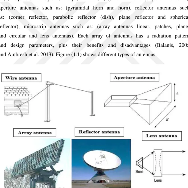
An antenna can have numerous shapes and sizes. Types of antennas are (e.g., dipoles, monopoles, loops, helices, yagi-uda and large-period antenna), aperture antennas such as: (pyramidal horn and horn), reflector antennas such as: (corner reflector, parabolic reflector (dish), plane reflector and spherical reflector), microstrip antennas such as: (array antennas linear, patches, planer and circular and lens antennas). Each array of antennas has a radiation pattern and design parameters, plus their benefits and disadvantages (Balanis, 2005 and Ambresh et al. 2013). Figure (1.1) shows different types of antennas.
Different type of antennas, frequency bands, Properties, gain values are presented in Table (1.1).
Table 1.1. Antenna on frequency basis (Devi and Rawat , 2016)
Types of antenna Frequency Band Designation
Vertical Radiators, Triatic antenna, Top-loaded Monopoles, T and Inverted L antennas, Valley-span
antenna, Trideco antenna
30-300 KHz Low Frequency (LF)
Radiators (monopoles and dipoles), directional antennas 300-3000 KHz Medium Frequency (MF) Log periodic antenna, Vertical whip antenna, conical
monopole and Inverted Cone antennas, Fan dipole antenna, Rhombic antenna
3-30 MHz High Frequency (HF)
Yagi-Uda antennas, log periodic antennas, discone antennas, Helical antennas, parabolic antennas, Panel
antennas, Corner reflector antennas
30-300 MHz Very High Frequency
(VHF) Yagi-Uda antennas, log periodic antennas, Panel
antennas, Helical antennas, parabolic antennas, Corner reflector antennas, discone antennas.
300-3000 MHz Ultra-High Frequency (UHF) Parabolic antenna, pyramidal horn antennas, discone
antennas, monopoles and dipoles antennas, Microstrip patch antennas, fractal antennas.
3-30 GHz Super High Frequency
(SHF) Parabolic antenna, pyramidal horn antennas, discone
antennas, monopoles and dipoles antennas, Microstrip patch antennas, fractal antennas.
30-300 GHz
Extremely High Frequency
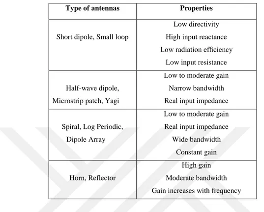
Table 1.2. Property of antennas are presented (Stutzman and Thiele, 2012)
A common design condition is to find an antenna to achieve the desired gain value. Some types of antenna and the corresponding gain values are presented in Table (1.3).
Table 1.3. Gain value of different kind of antennas (Rautio J. C., 2008)
1.1. Reflector Antennas
Reflector antennas redirect electromagnetic and refocus it in a certain direction. Reflector antennas are commonly used in space crafts for long
Type of antennas Properties
Short dipole, Small loop
Low directivity High input reactance Low radiation efficiency
Low input resistance
Half-wave dipole, Microstrip patch, Yagi
Low to moderate gain Narrow bandwidth Real input impedance
Spiral, Log Periodic, Dipole Array
Low to moderate gain Real input impedance
Wide bandwidth Constant gain
Horn, Reflector
High gain Moderate bandwidth Gain increases with frequency
Types of antenna Gain value
Electrically small antennas, Loops, Dipoles/monopoles
5 dB or less
Microstrip patches, Planar frequency-independent antennas (e.g. spirals)
5dB to 8dB
Yagi-Uda, Log periodic dipole array, Helix (axial mode)
8dB to15dB
distance communication (Balanis, 2005). Reflector antennas are characterized by narrow main beams and very high gain. Studies on reflector antennas during the last decade were about paraboloids. This is due to the application of dish antennas in earth stations for microwave satellite and space communications (Kildal, 1984). These kinds of antennas have two different types, right cylinder and paraboloid (Khan et al., 2016; Kaaya et al., 2014). Several common kinds of reflector antennas are the corner reflector, plane reflector and parabolic reflector (Balanis, 2005). Parabolic reflectors gather and concentrate parallel incoming radio wave beams and its emphasis on an actual antenna at focal point on focus (Patil et al., 2014).
Reflector antennas are commonly used at ultra-high frequency, millimeter and submillimeter wavelengths for radio astronomy, centimeter, earth remote sensing systems, radar, radio and television. Methods and the theory for calculating the reflector antenna have been developed well now (Gorobets et al., 2013). The reflector pattern can be controlled either by forming a feeding antenna pattern or by shaping the reflector surface, both of which have its advantages and disadvantages (Bagheri-Korania et al., 2016).
1.2. Parabolic Antenna
A parabolic antenna has a parabolic reflector which is a cross-sectional form of parabola with a curved surface, to direct and receive radio waves. The most popular form is called parabolic dish or dish antenna (Dean, 2000; Ingale et al., 2008). Parabolic reflectors are commonly antennas that is used in satellite, point-to-point communication systems, power transmission and microwave radar (Hagen et al., 1996).
Parabolic reflectors are formed such as parabola. Electromagnetic waves can be focused at the beam and precisely targeted locations. Because of this property, the parabolic antennas are typically used by dish television companies and satellite communications. ,
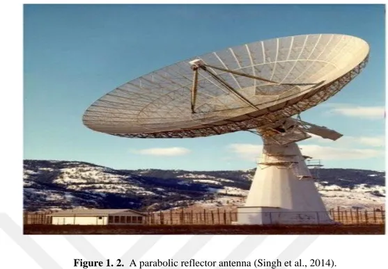
parabolic reflectors produce a high-gain pencil beam with low side lobes and good cross-polarization discrimination characteristics. Fig. (1.2) shows a parabolic refletor antenna (Balanis, 2005).
Figure 1. 2. A parabolic reflector antenna (Singh et al., 2014).
Reflector antennas are used since the discovery of electromagnetic wave propagation in 1888 (Fung C., 2011). Though reflector antennas take many geometric formations, the most popular shapes are the curved reflectors, corner, and plane (Telagarapua et al., 2011). Focal point is the point which radiation converges in a spot. A symmetrical point is known as the vertex on the parabolic surface. Rays which emerge in a parallel forming are usually said to be collimated. In practice, collimation is often used to characterize highly directional antenna properties although the emitted rays are not completely parallel (Balanis, 2005). The satellite television dish antenna is the most popular example for parabolic antennas. The parabolic antenna is like a concave mirror which combines incoming light and focuses it in the lens (Liu et al., 2013).
Focal length of parabolic reflector is an important element and equal to the distance from focus to the vertex. Aperture length of a parabolic reflector is described as antenna diameter. A parabolic reflector is described by the diameter (d) and focal length (f) of the aperture. f/d ratio is used to determine the diameter of parabolic reflector and its aperture. If the ratio of f/d is large such as 0.5 to 0.8 needs to show its strength at a narrower angle. Feed should be further away from the dish and larger diameter. If f/d is low the feed will be
close to the dish. Dish should be illuminated at a wide angle (Chaurasiya and Kumar, 2015). A typical parabolic reflector antenna is shown in Figure (1.3).
Figure 1.3. A typical parabolic reflector antenna (Chaurasiya and Kumar, 2015).
1.3. Reflector Antenna Parameters
Before antenna design one should know its properties (Ambresh et al., 2013). Some of the parameters are required to describe the antenna performance (Balanis, 2005).
1.3.1. Antenna pattern (Radiation pattern)
The radiation pattern is the electromagnetic field of distributed antenna radiation in coordination at a fixed distance (Fung, 2011). In the usual case, the radiation pattern is a function for directional coordinates and is particular in the far field. Radiation characteristics include field strength, radiation intensity, polarization or phase (Anonymous, 1983 a). Therefore, the antenna pattern shows how the power is distributed in the space (Devi and Rawat, 2016).
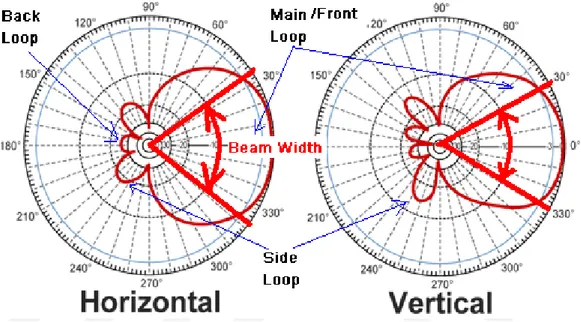
The pattern that is represented by the power density it is called power pattern. The power pattern is commonly used in mobile communications. The antenna pattern is usually represented by two patterns that are perpendicular to each other on a main level. This is called surface pattern. The power in some
directions is strengthened while the power in some directions is weakened. The lobes of different shapes and zero points form. The main lobe has the highest power. The first side lobes are near the main lobe and has the second highest power. The second side lobes have the third highest power (Fung, 2011). The horizontal and vertical patterns of a directional antenna is shown in Fig. (1.4).
Figure 1.4. Radiation pattern of reflector antennas (Anonymous, 2011 d).
1.3.2. Directivity (D)
The directivity is the ratio of the maximum radiation intensity to the average radiation intensity of the antenna. The directive gain is fully achieved when the incident polarization is the same as polarizing the antenna for transmission (Anonymous, 1983 a). The relationship between directivity and antenna gain is given by (Kraus, 2001)
G = η D (1-1) where G is gain, η is the efficiency of the antenna, and D is the directivity.
1.3.3. Gain (G)
Gain is a measure of antennas that shows how well they direct the input power of radiation in a given direction and is measured at the peak radiation intensity (Milligan, 2005). It depends on the efficiency and directivity. If the
efficiency is not 100 percent, the gain is less than the directivity. It is usually expressed in dB and can be negative (Kraus, 2001).
A number of factors affect the gain of the parabolic antenna. These factors are: (Anonymous, 2017 b).
1. Surface reflective diameter: The greater the antenna surface reflector diameter, the greater the parabolic reflector gain.
2. Antenna efficiency: The efficiency of the antenna greatly affects the overall parabolic reflector gain. Typical efficiencies range from 50% to 70%.
3. Operating wavelength: The gain of the parabolic reflector antenna depends on the size of the reflector in terms of wavelengths. Therefore, if the same reflector is used at two various frequencies, the gain will be various and inversely proportional to the wavelength.
1.3.4. Antenna efficiency (η)
Antenna efficiency is the ratio of the aperture effective area (Ae) to its
actual physical area (A). (Anonymous, 1983 d). It is the percentage of the physical aperture area that actually picks up radio frequency (RF) energy (Cheng, 1992).
Ae = A η (1-2)
1.3.5. Bandwidth (B)
The bandwidth is the frequency range at which its performance corresponds to certain properties of a specified standard. Bandwidth is often stated in percentage (Anonymous, 1983 a).
1.3.6. Beamwidth
The beamwidth is angular separation between two identical points on the opposite side of the maximum pattern. There are a number of beamwidths in an antenna pattern. The most commonly used beamwidths is the Half-Power Beam width (HPBW) (Balanis, 2008).
1.3.7. Polarization
The antenna polarization determines the orientation of E (electric) and H (magnetic) waves. Linear polarization includes horizontal, vertical, or oblique. The nonlinear polarization model includes the right-hand and left-hand circular (also elliptical) (Ambresh et al., 2013). Co-polarization and cross-polarization directions are defined for the radiating E and H planes. These directions in spherical coordinates are in correspondence with the spherical wave fronts of the propagation wave. In general, the co-pol and cross-pol directions are E field and H field directions, respectively. Received power for a co-pol oriented antenna is maximum but received power is minimum for cross-pol orientation (Anonymous, 2017 c). Cross-cross-polarization in a rectangular coordinate system, one unit vector is taken as a reference polarization direction, another as a cross polarization direction (Silver, 1949). Unbalanced fed like a dipole, reflector induced cross-polarization is zero in the principal planes and is maximum in the 45º plane. The largest cross-polarized across the reflector occur in the 45º planes (Stutzman, 2012).
1.4. Advantages of Reflector Antenna
The following are the major advantages of a parabolic antenna: 1. Its directivity is high (Behl et al., 2014).
2. It works like a reflective flashlight to receive radio waves from a unique direction or direct radio waves in a narrow beam (Di Fonzo and Feutei, 1970).
3. Parabolic antennas h a v e some of the highest gains. High gain using a parabolic reflector can be achieved by constructing a suitable dimension (Merabtine et al., 2006).
4. Parabolic antennas offer the best angular resolution at lower costs (Gardelli et al., 2004).
5. They can produce the narrowest beam widths (Gardelli et al., 2004). 6. Parabolic antennas offer widest bandwidth (Gardelli et al., 2004).
1.5. Disadvantages of Reflector Antenna
Such as all antenna forms, a parabolic reflector has limitations and drawbacks: The parabolic antenna itself is only portion of the antenna. (Anonymous, 2017 b).
1. The parabolic reflector requires a feed system to be put at the focus.
2. Paraboloid reflector is needed carefully to reflect radio signals. In addition, a feed system is also needed.
3. The reflector antenna is not as small as some kinds of antenna.
1.6. Parabolic Reflector Antenna Applications
There are many field that can use a parabolic / dish antenna:
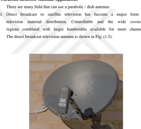
1. Direct broadcast or satellite television has become a major form of television material distribution. Controllable and the wide coverage regions combined with larger bandwidths available for more channels. The direct broadcast television antenna is shown in Fig. (1.5).
Figure 1.5. Direct broadcast television antenna (Anonymous, 2017 b).
2. The directive antennas used to supply sufficient gain to take signals from only one satellite in the sky. (Anonymous, 20167 b; Samii et al., 2015).
3. Terrestrial microwave links are used for terrestrial telecommunications infrastructure links. These days is being used to provide backhaul to the mobile phone / cellular backhaul. ((Anonymous, 2017 b; Ingale et al., 2008). The microwave links is shown in Fig. (1.6)
Figure 1.6. Microwave links (Anonymous, 2017 b).
4. Satellite communications, many satellite uplinks, or those for communication satellites require high levels of gain to ensure the optimum signal conditions and that transmitted power from the ground does not affect other satellites in close angular proximity. (Liu et al., 2013; Love, 2009). Parabolic antennas are used for point-to-point communication, like wireless local area network / wide area network satellite communications, data communication links, and spacecraft communication antennas. It is used at UHF and SHF frequencies of the radio spectrum. (Behl et al., 2014).
5. Radio astronomy is an area that requires very high levels of directivity and gain. so, a parabolic reflector is the ideal option. (Anonymous, 2016 b; Behl et al., 2014).
they are designed to transfer a narrow beam of radio waves to locate objects such as airplanes. Parabolic antennas have become common by the world-wide use of home satellite television receivers (Behl et al., 2014; Gardelli et al., 2004).
1.7. The Aim of The Study
The aim of the present work is to investigate the design parameters of parabolic dish antennas. The aim of this work can be described as follows:
1. The effect of f/d (focal length to the size of the aperture) ratio. f/d is an important characteristic of parabolic reflector and its value usually varies from 0.5 to 0.8. If f/d is above 0.8 the reflector becomes flat and does not introduce cross-polarization.
2. The effect of antenna size on the parabolic reflector antenna gain.
3. The study of the parabolic reflector antenna radiation pattern as a function of f/d from 0.5 to 0.8 for operating frequency bands from 1 GHz to 12 GHz.
4. To find out the optimum design of the parabolic reflector antenna by considering directivity for same f/d and operating frequency from 1 GHz to 10 GHz.
2. LITERATURE REVIEW
During the discovery of radio waves in 1887, cylindrical parabolic reflectors were used with spark-excited dipole antennas. German physicist Heinrich Hertz built the first parabolic reflector antenna in 1888. During 1930s, Guillermo Marconi used a parabolic reflector while he was investigating communication from his boat in the Mediterranean. In 1931, a 1.7 GHz telephone link was introduced via the English Channel using 3 meter dishes (Love, 2009). The pioneering radio astronomer Grot Ripper built a 9 meter dish antenna in 1937 (Stutzman and Thiele, 2012). The early development of the radio was limited to low-frequency inappropriate parabolic antennas (Love, 2009).
Antenna technology remains primarily dormant until the 1940s, when microwaves and UHF, like magnetrons, klystrons and travel wave amplifiers were developed. This led to the design of antennas, like horns, reflectors and waveguides which later incorporated two systems into astronomy (Silver, 1949).
Dish antennas were commonly used in terrestrial communications networks during 1960s (Olver et al., 1994). The 100-meter Radio Telescope was completed in 1962 and it is still the world's largest parabolic dish (Behl et al., 2014). The first satellite communication parabolic antenna was built in 1962 (Gardelli et al., 2004).
During the late 1980s, another important development occurred in the form of reflector technology forms. Large-scale deployment of wireless communications began in the 1980s, which turned out to be the re-invention of radio communications a century after their first deployment in a fully directive parabolic dish (Rao et al., 2013).
Balanis (2005), have investigated the General radiation characteristics (antenna efficiency, antenna pattern, polarization discrimination, etc.) can be improved for a reflector antenna if the structural configuration of its surface is upgraded. Paraboloidal reflectors are used large aperture ground-based antennas most widely. Paraboloidal reflectors produce good properties of cross-polarization and a beam of high gain pencil with low side lobes, when the fed
efficiently from the focal point. Paraboloidal reflectors has introduced into a way that is widely used for Paraboloidal antenna for low noise applications, as in radio astronomy, and is considered a good compromise between performance and cost. Building a large project requires not only a large financial budget, but also a difficult structural project, because it must withstand harsh weather conditions.
Miinoli (2009) observed that the gain is a function of diameter and wavelength. Gain increases with lower wavelength. The antenna has a diameter of 3 meters and an efficiency of 0.55 gain of 19540 at the c band uplink frequency of 6 GHz and the wavelength of 0.050 m. The gain was 42.9 dB in the Ku band. With an uplink frequency of 14 GHz and a wavelength of 0.021 m, 3-meter antenna gain was 50.44 dB. The higher the frequency the higher the gain of the antenna of the same size. The 6ft c-band antenna gain was 35 dB, while the same size of the antenna has a 44.5 dB gain at Ku band.
Rathod and Kosta (2009), worked on the frequency range between 4.8 GHz to 5.9 GHz. The most important factor of the dish is size because it determines the maximum gain that can be achieved at a given frequency and the resulting beamwidth. The f/d ratio is the essential factor to design of the dish. The side lobes are reduced at lower f/d ratio.
Azevedo (2009), explained that directivity and the sidelobe level structure are important for antenna design. An interesting case is the pencil beam pattern, where the main lobe indicates the desired direction of radiation. A technique was introduced that controls the sidelobe levels of the array factor for plane patterns in a manner similar to linear arrays.
Oguzer et al. (2010), studied that parabolic reflector antennas have large diameters such as 50 λ to 80 λ and larger. The effect of the axial shift of the extract from the geometric focus on the radiation properties of a parabolic reflector. It was studied by a precise mathematical accurate MAR technique.
Telagarapu et al. (2011) found that the far field radiation pattern of a parabolic reflector depends on the initial radiation pattern, the radiation pattern of the feed element, and the type and dimensions of the used reflector. Therefore, their research is the first analysis of the prototypes of different
elements such as the dipole. In addition, they calculated the efficiency of beams and dipole multiplication patterns at various lengths. A comparison was made between the dipole, square angles and horn feeds based on properties like directivity and intensity. Parabolic reflector characteristics like f/d, radiation pattern, and gain, have been analyzed. At 3 GHz, 6 m focus, 6 m diameter, they found that the maximum directivity was 41.8852 (dB).
Salman et al. (2012) studied the theoretical analysis of the parabolic reflector antenna radiation pattern by applying two methods; Aperture Field Method (AFM) and Induced Current Method (ICM). They studied the radiation fields of parabolic reflector antenna fed by two types of microstrip antennas. The best results were obtained for the aperture diameter of d = 20 λ and f/d ratio that taken at edge illumination about -3dB. As a result, both methods are in a complete agreement in studying of radiation patterns in principle planes, E and H, at far-field region.
Gorobets et al. (2013) studied the effect of the parabolic reflector size (in calculating the diameter of 10 to 100 wavelength) and focal length (the focal length of the reflector diameter ranged from 0.5 to 3.0) in detail. They found that optimum cross-polarized radiation is weakly dependent on the reflector diameter and decreases with increasing the reflector depth. The cross-polarization of the radiation reflector antennas are larger if the smallest reflector diameter and focal length are less.
Chaurasiya and Kumar (2015) have calculated efficiency patterns and beam width for various central frequencies, diameters and focal lengths of parabolic reflector antennas. They concluded that the reflector directivity is the best when the focal length is 14.4 mm, the center frequency is 2.79 GHz, and the parabolic dish diameter is 26.9 mm.
Bagheri-Korania et al. (2015): Khan (2016) stated that the reflector pattern can be controlled either by forming a feed antenna pattern or by shaping the reflector surface. Radiation patterns of the parabolic reflector depend on the feed component, as well as the reflector material and measurements.
Haddadi and Ghorbani (2016) showed that surface distortions change the radiation characteristics of reflector antennas. They used variable derivatives to show the sensitivity of the radiation pattern to surface deformation.
3. METHOD 3.1. Method
To design a parabolic reflector dish antenna, it is important to determine the f/d values. Equations (3-5) and (3-13) are used to evaluate the radiation pattern and directivity for any geometrical design of the antennas. The Parabolic Reflector Dish Antenna Program written in the MATLAB programming language was used to evaluate necessary parameters after some modification. The original program was taken from Arizona State University, written by Seunghwan Yoon. The program was used to evaluate the radiation pattern for a parabolic dish reflector along with directivity, beam width, polarization for near to and far zone fields.
The f/d (focal length/diameter of the dish) ratio is the primary factor governing the feed design of the dish. It is directly related to the beam width of the feed needed to illuminate the dish effectively. Two dishes of the same diameter but various focal lengths require various design of feed if both dishes are to be luminous efficiently the feed will be away from the dish.
In this work, different f/d are applied to determine parabolic reflector dish antenna. f/d values varied from 0.5 to 0.8. Directivity, gain, radiation pattern for parabolic reflector dish antenna are evaluated in the same range of f/d values. The evaluation of the parameters is used for frequencies from 1 GHz up to 10 GHz for different bands. All these parameters were evaluated for f/d = 0.5, 0.6, 0.7, and 0.8. The results are given in chapter Four. The comparison of the results of the present work at 30 GHz and the results evaluated by Balanis, 2005 are given in Fig. (3.1). The agreement of results is excellent within certain error.
Figure 3.1. Antenna directivity for parabolic reflector antenna versus diameter to wavelength ratio (d/λ) for the present work at 30 GHz compared with Balanis, 2005.
.
Beam formation by parabolic reflectors:
A parabola is a two-dimensional curve. It is defined as the set of points that have equal distance from a straight line (called directrix) and a point F not on the line. A parabola with focus F and vertex O is shown in Fig. (3.2).
Figure 3.2. Geometry of a parabolic reflector antenna. OF is the focal length, F is focus, O is the vertex and OŌ is the axis of the parabola
The parabola curve equation is given by:
Y2= 4 f x (3-1)
The open mouth (d) of the parabola is known as aperture. The ratio of focal length to aperture size known as f over d ratio, f/d, which is an important characteristic of parabolic reflector. f/d is varied from 0.5 to 0.8 in the present study.
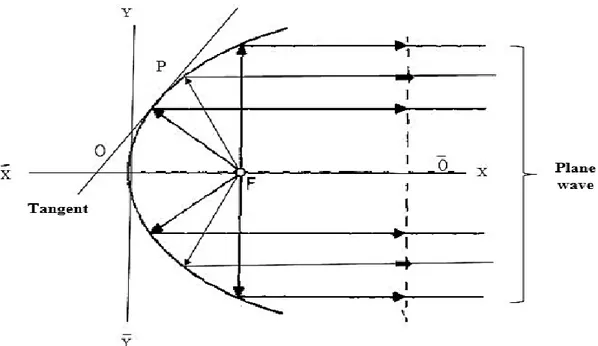
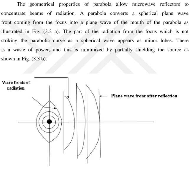
The geometrical properties of parabola allow microwave reflectors to concentrate beams of radiation. A parabola converts a spherical plane wave front coming from the focus into a plane wave of the mouth of the parabola as illustrated in Fig. (3.3 a). The part of the radiation from the focus which is not striking the parabolic curve as a spherical wave appears as minor lobes. There is a waste of power, and this is minimized by partially shielding the source as shown in Fig. (3.3 b).
Figure 3.3 a. Production of the plane wave front by the parabolic reflector with an omnidirectional source at the focus
Figure 3.3 b. With partially shield source
3.2 Theoretical Aspect
Regardless of the type of application of a parabolic antenna or antenna system, all antennas possess certain basic characteristics that will be discussed in this chapter. Important characteristics of a reflector antenna are usually given in certain terms like: radiation intensity, directive gain, radiation pattern, directivity, power gain, etc.
3.2.1. Radiation pattern
It is a graph showing the radiation pattern of an antenna as the three-dimensional solid figure. It is obtained by a plane passing through the fixed point e.g. the center of the sphere. The radiation pattern has various kinds such as directional, omnidirectional, fan beam, pencil beam, and beam shape (Balanis, 2005).
3.2.2. Radiation pattern characteristics
Typical radiation pattern is shown in Fig. (3.4) in linear units instead of dB. The performance and difference in the radiation parameters of parabolic reflector antenna depends on the type of feed elements that is used for exciting its surface. Lobe radiation - a clear peak intensity of radiation is surrounded by
Plane wave front after
reflection shield
areas of weaker radiation intensity. It consists of several lobes: (Stutzman and Thiele, 2012).
1. Main Lobe (major lobe, main beam) - radiation lobe in the direction of maximum radiation.
2. Minor Lobe - any radiation lobe other than the main lobe. Minor lobes consist of side lobes and back lobes.
a. Side Lobe - lobe radiation in any direction other than the direction (s) of the meant radiation.
b. Back Lobe - lobe radiation versus the main lobe.
3. Half-Power Beamwidth (HPBW) - the angular width of the main beam at the half-power points.
4. First Null Beamwidth (FNBW) - angular width between the first nulls on either side of the main beam.
The antenna power patterns can be represented in cartesian or polar coordinates, as shown in Fig. (3.4).
(a)
(b)
Figure 3.4. The characteristics of Antenna power patterns (a) In polar coordinates (linear scale) Agnihotri, 2013)
Radiation inntensity is the radiated power per solid angle (Balanis, 2005 and Kraus, 2001).
Ptot = Pavg . ds (3-1)
In the far field, the total time-average radiated power is given by
P
avg= P
avgŕ
(3-2)ds = ŝ ds = ŕ r
2dθ dϕ (3-3)
Ptot = Pavg r sinθ dθ dϕ (3-4)
If we define Pavg r2 = U (θ, Φ) as the radiation intensity, then the total radiated power
(Ptot) is given by:
Ptot = (3-5)
3.2.3. Directivity
Directivity is the ratio of radiation intensity to the average radiation intensity in a given direction. The average radiation intensity is the sum of the radiated power divided by four. Directivity can be written as follows: (Balanis, 2005 and Milligan, 2005).
D ( ) =
D ( ) = (3-7)
D ( )
=
(3-8)D ( )
=
(3-10)D ( ) = (3-11)
D = (3-12) Directivity for a parabolic antenna is given by (Miinoli D., 2009)
D == 4 π A /
λ
2(3-13)
where A is the physical aperture area, λ is wave length, and ΩA is the beam solid angle .
3.2.4. Gain
Power gain or simply gain (G) is a dimensionless measure that combines antenna efficiency η and directivity D (Stutzman and Thiele 2012).
4. RESULTS AND DISCUSSION 4.1. Directivity Versus f/d Ratio
Location of the microwave bands in the electromagnetic spectrum used in this study are given in Table (4.1) (Pozar, 2012).
Table 4.1. The microwave frequency bands location in the electromagnetic spectrum
At d = 0.25 m the directivity of the parabolic reflector antenna for f/d equal to (0.5, 0.6, 0.7, 0.8) are applied. Directivity increased gradually and the highest directivity occurs at -13.3. The simulation results for directivities of parabolic reflector antennas for different diameter and f/d ratio are given in Table (4.2).
Table 4.2. The directivity of parabolic reflector antenna versus f/d at different diameter
Frequency Band Frequency Range
L band 1–2 GHz S band 2–4 GHz C band 4–8 GHz X band 8–12 GHz f/d D (dB) d = 0.25 m D (dB) d = 0.5 m D (dB) d = 0.75 m D (dB) d = 1 m D (dB) d = 2 m D (dB) d = 3 m D (dB) d = 6 m 0.5 -17.3 -11.7 -7.8 -7.8 1.7 6.1 14.3 0.6 -16 -10.5 -6.1 -3.2 3.8 8.2 18.6 0.7 -14.7 -8.3 -4.7 -1.7 5.5 10.3 19.7 0.8 -13.3 -7 -3.2 -0.32 7.1 12.3 27.1
4.2. Directivity Versus Frequency
The directivity of the reflector antenna versus frequency for four cases are performed in the present study. When f/d = 0.8 the antenna has the highest directivity. Directivity decreases gradually as f/d value is equal to 0.8, 0.7, 0.6 and 0.5. The directivity of reflector antenna versus frequency of antenna diameters d = (0.25m, 0.50m, 0.75m, 1m, 3m, and 6m) are shown in Figs. (4.1), (4.2), (4.3), (4.4), (4.5), (4.6), and (4.7) respectively.
Fig. (4.1) shows the directivity of the reflector antenna versus frequency for the antenna diameter is equal to 0.25 m. The directivity is the highest (-13.3 dB) when f/d is equal to 0.8 at 4 GHz. The maximum directivity occurs (-17.3 dB) obtained when f/d is equal to 0.5 at 3 GHz.
Figure 4.1. Directivity of reflector antennas versus frequency with f/d = (0.5, 0.6, 0.7, 0.8) and diameter = 0.25 m
Fig. (4.2) shows the directivity of the reflector antenna versus frequency for the antenna diameter equal to 0.5 m. The directivity in all cases are fluctuating. Directivity is equal to (-7) dB when f/d=0.8 and (-11.7) dB when f/d = 0.5.
Figure 4.2. Directivity of reflector antennas versus frequency with f/d = (0.5, 0.6, 0.7, 0.8) and diameter = 0.5 m
Fig. (4.3) shows the directivity of the reflector antenna versus frequency for the antenna diameter equal to 0.75 m. In all cases directivity fluctuated sharply. Directivity is equal to (-3.2) dB when f/d = 0.8, and -4.7dB when f/d = 0.7.
Figure 4.3. Directivity of reflector antennas versus frequency with f/d = (0.5, 0.6, 0.7, 0.8) and diameter = 0.75 m
Fig. (4.4) shows the directivity of the reflector antenna versus frequency when the antenna diameter equal to 1 m. In all cases directivity fluctuated dramatically. Directivity is equal to -0.32 dB when f/d = 0.8, and for other f/d values the directivity decresed.
Figure 4.4. Directivity of reflector antennas versus frequency with f/d = (0.5, 0.6, 0.7, 0.8) and diameter = 1 m
Fig. (4.5) shows the directivity of the reflector antenna versus frequency for the antenna diameter equal to 2 m. There is no fluctuation when f/d is equal to (0.7, o.6). When d = 2 m and f/d = 0.7 the directivity is optimum and equal to 5.5 dB at 5 GHz located in c band.
Figure 4.5. Directivity of reflector antennas versus frequency with f/d = (0.5, 0.6, 0.7, 0.8) and its diameter = 2 m
Fig. (4.6) shows the directivity of the reflector antenna versus frequency for the antenna diameter equal to 3 m. Directivity fluctuates when f/d = (0.5, 0.6, 0.7). For d = 3 m and f/d = 0.8 the directivity is optimum and equal to 12.3 dB at 6 GHz (c band).
Figure 4.6. Directivity of reflector antennas versus frequency with f/d = (0.5, 0.6, 0.7, 0.8) and diameter = 3 m
Fig. (4.7) shows the directivity of the reflector antenna versus frequency for the antenna diameter equal to 6 m. The directivity fluctuates when f/d = (0.5, 0.6, 0.8). Maximum directivity occurs when f/d = 0.8 at 6 GHz (c band).
Figure 4.7. Directivity of reflector antennas versus frequency with f/d = (0.5, 0.6, 0.7, 0.8) and its diameter = 6 m.
Figures (4.1), (4.2), (4.3), (4.4), (4.5), (4.6), and (4.7) indicate the variation of the directivity of specific frequency for f/d = (0.5, 0.6, 0.7, 0.8). f/d = 0.8 is optimum. For d = 2 m, f/d = 0.7 the optimum is equal to 5.5 dB and frequency = 5 GHz is located in (c band). For d = 3 m, f/d = 0.8 the highest directivity is equal to 12 dB and frequency = 6 GHz (c band).
4.3. Radiation Patterns of Antennas Having Different Diameter
Radiation patterns for reflector antenna are drawn with f/d = 0.8 at different frequency by GHz at antenna’s diameter 0.25 meter, 0.5 meter, 0.75 meter, 1 meter, 2 meter, 3 meter and 6 meter the graphs of the radiation pattern are shown in Figs. (4.8), (4.9), (4.10), (4.11), (4.12), (4.13), and (4.14). The figures are drawn for normalized pattern reflector, absolute pattern as well as cross-polarization pattern for all given antennas. It can be seen that the optimum radiation pattern ocurs when diameter is 2 meter at frequency of 12 GHz. The radiation pattern becomes boarder in other cases.
Fig. (4.8) shows radiation patterns for diameter = 0.25 m. Many side lobes exist and the main lobe is disappeared.
(a) (b)
(c)
Figure 4.8. Radiation patterns in two dimensions for f/d = 0.8, at frequency = 8 GHz and diameter = 0.25 m with
(a) Normalized pattern of parabolic reflector (CO-POL). (b) Absolute pattern of parabolic reflector (CO- POL). (c) Pattern of parabolic reflector (Cross- POL)
Fig. (4.9) shows radiation patterns for diameter = 0.5 m. Many side lobes exist and the main lobe is disappeared.
(a) (b)
(c)
Figure 4.9. Radiation patterns in two dimensions for f/d = 0.8, at frequency = 4 GHz and diameter = 0.5 m with (a) Normalized pattern of parabolic reflector (CO-POL). (b) Absolute pattern of parabolic reflector (CO- POL). (c) Pattern of parabolic reflector (Cross- POL)
Fig. (4.10) Shows radiation patterns for diameter = 0.75 m. Many side lobes exist and the main lobe is disappeared.
(a) (b)
(c)
Figure 4.10. Radiation patterns in two dimensions for f/d = 0.8, at frequency = 2 GHz and diameter = 0.75 m with (a) Normalized pattern of parabolic reflector (CO-POL). (b) Absolute pattern of parabolic reflector (CO- POL). (c) Pattern of parabolic reflector (Cross- POL).
Fig. (4.11) shows radiation patterns for diameter = 1 m. Main lobe is narrow and the side lobes are small.
(a) (b)
(c)
Figure 4.11. Radiation patterns in two dimensions for f/d = 0.8, at frequency = 10 GHz and diameter = 1 m with (a) Normalized pattern of parabolic reflector (CO-POL). (b) Absolute pattern of parabolic reflector (CO- POL). (c) Pattern of parabolic reflector (Cross- POL)
Fig. (4.12) shows radiation patterns for antenna diameter is equal to 2 m. The pattern has low side lobes and a narrow main lobe.
(a) (b)
(c)
Figure 4.12. Radiation patterns in two dimensions for f/d = 0.8, at frequency = 12 GHz and diameter = 2 m with
(a) Normalized pattern of parabolic reflector (CO-POL). (b) Absolute pattern of parabolic reflector (CO- POL). (c) Pattern of parabolic reflector (Cross- POL).
Fig. (4.13) shows radiation patterns for antenna diameter equal to 3 m. Many side lobes exist and the main lobe is disappeared.
(a) (b)
(c)
Figure 4.13. Radiation patterns in two dimensions for f/d = 0.8, at frequency = 1 GHz and diameter = 3 m with
(a) Normalized pattern of parabolic reflector (CO-POL). (b) Absolute pattern of parabolic reflector (CO- POL). (c) Pattern of parabolic reflector (Cross- POL)
Fig. (4.14) shows radiation patterns for diameter = 1 m. Many side lobes exist and main lobe is not clear.
(a) (b)
(c)
Figure 4.14. Radiation patterns in two dimensions for f/d = 0.8, at frequency = 10 GHz and diameter = 6 m with (a) Normalized pattern of parabolic reflector (CO-POL). (b) Absolute pattern of parabolic reflector (CO- POL). (c) Pattern of parabolic reflector (Cross- POL)
In the real-world antenna radiation plots can be very complex because they are three-dimensional. Cartesian coordinates is used to simplify the plots. Radiation plots are often shown either at the antenna or plane axis or plane vertical to the axis and are referred respectively to azimuth "E-plane" and the elevation "H-plane".
4.4. Radiation Pattern Versus Azimuthal Angle for Reflector Antennas
Cross-polarization for reflectors is the cross-polarization ratio to co-polarized pattern peak value. The lack of cross-polarization in the principal planes in Figs. (4.15), (4.16), (4.17), (4.18), (4.19), (4.20), and (4.21). Figures show pattern data computed with the MATLAB program for reflector antenna using physical optics and surface current integration. The figures correspond to the reflector antenna diameter d = 0.25 m, 0.5 m, 0,75 m, 1 m, 2 m, 3 m, and 6 m respectively for the same antenna parameters. These cross-polarization properties are also true for the reflector radiation.
(a)
(b)
Figure 4.15. Principle plane patterns for a uniform amplitude, uniform phase parabolic reflector antenna d = 0.25 m. at 8 GHz for f/d = 0.8
(a) Parabolic reflector antenna (Cross- Pol) (b) Parabolic reflector (Co- Pol)
(a)
(b)
Figure 4.16. Principle plane patterns for a uniform amplitude, uniform phase parabolic reflector antenna d = 0.5 m. at 4 GHz for f/d = 0.8
(a)Parabolic reflector antenna (Cross- Pol) (b) Parabolic reflector (Co- Pol)
(a)
(b)
Figure 4.17. Principle plane patterns for a uniform amplitude, uniform phase parabolic reflector antenna d = 0.75 m. at 2 GHz for f/d = 0.8
(a)Parabolic reflector antenna (Cross- Pol) (b) Parabolic reflector (Co- Pol)
(a)
(b)
Figure 4.18. Principle plane patterns for a uniform amplitude, uniform phase parabolic reflector antenna d = 1 m. at 10 GHz for f/d = 0.8
(a)Parabolic reflector antenna (Cross- Pol) (b) Parabolic reflector (Co- Pol)
(a)
(b)
Figure 4.19. Principle plane patterns for a uniform amplitude, uniform phase parabolic reflector antenna d = 2 m. at 12 GHz for f/d = 0.8
(a)Parabolic reflector antenna (Cross- Pol) (b) Parabolic reflector (Co- Pol)
(a)
(b)
Figure 4.20. Principle plane patterns for a uniform amplitude, uniform phase parabolic reflector antenna d = 3 m at 1 GHz for f/d = 0.8
(a)Parabolic reflector antenna (Cross- Pol) (b) Parabolic reflector (Co- Pol)
(a)
(b)
Figure 4.21. Principle plane patterns for a uniform amplitude, uniform phase parabolic reflector antenna d = 6 m. at 10 GHz for f/d = 0.8
(a)Parabolic reflector antenna (Cross- Pol) (b) Parabolic reflector (Co- Pol)
5. CONCLUSIONS AND FUTURE WORK 5.1. Conclusions
According to the present analysis procedures and the results have been obtained for parabolic reflector antennas in chapter four, the following conclusions can be made. 1. Observing Table (4.2) the value of directivity for reflector antennas increases as
f/d increases. It reaches its maximum (optimum) values when f/d = 0.8. When f/d = 0.8 the antenna has the highest value of directivity. Directivity decreases gradually as f/d value decreases such as f/d = 0.7, 0.6 and 0.5. All these results are shown in Figs. (4.1) - (4.7).
2. The results that are given in Tables (4.2) indicate that the value of directivity increases with increasing diameter. Maximum (optimum) directivity occurs at 27.1 dB for diameter = 6 meter.
3. The diameter of the parabolic dish is 3 m, optimum directivity is 12.3 dB at 6 GHz, which located in (c band) and this can be noticed in fig. (4.6). At d = 6 m the directivity increases, but fluctuated as shown in Fig. (4.7) which means the best response of this reflector occurs when d = 3 meter.
4. The optimum radiation patterns occur at antenna diameter of 2 meter at frequency = 12 GHz. At this diameter, the radiation becomes boarder and the propagation of EMW is the highest. It has a wide half power beam width while side lobes become small which gives best response of this reflector. This is clearly seen in Fig. (4.12).
5. The lack of cross-polarization in the principal planes in Figs. (4.15) up to (4.21).
Reflector antennas are characterized by narrow beam antenna and high gains around 30 dB. In the present work, narrow main beams obtained and optimum gain equal 27 dB.
5.2 Future Work
The present work may be extended for the future work as in the following:
1. The main future work on this project can be about the design and manufacturing of antennas and the measuring scattering parameters and radiation patterns.
2. Configuration and implementation of reflector antennas design will be made to measure all parameters including: directivity, gain and beam width by using network analyser. All measured parameters will be compared with theoretical values.
6. REFERENCES
Agnihotri, A., Prabhu, A. and Mishra, D., 2013. Improvement in Radiation Pattern Of Yagi-Uda Antenna Research Inventy: International Journal Of Engineering And Science, 2(12), pp.26-35.
Agrawal, P. and Sharma, S.K., 2014. Design and Analysis of Fractal Triangle Microstrip Patch Antenna with Strip Line Feed for Dual-Band Frequency. International Journal of Emerging Technology and Advanced Engineering, 4(7), pp.641-645.
Ambresh, P.A., Hadalgi, P.M. and Hunagund , P.V., 2013. Various Antennas and Its Applications in Wireless Domain: A Review Paper, 5(1), pp.21-25.
Anonymous-a, Institute of Electrical and Electronics Engineers, 1983. IEEE Standard
Definitions of Terms for Antennas. 17(3) Pp.264-269
Anonymous-b <http://www.radioelectronics.com/info/antennas/parabolic/parabolic reflector.php >, [5 May 2017]. Anonymous-c,<https://en.wikipedia.org/wiki/E-plane_and_H-plane>,[27-February-2017]. Anonymous-d,<http://denmasbroto.com/cetak-13-antenna-basic-theory.html>,[22-8-2011].
Azevedo, J.A.R., 2009. Antenna pattern control of planar arrays for long distance communications. Advances in Space Research, 43(11), pp.1603-1610.
Bagheri-Korani, E., Mohammadpour-Aghdam, K., Ahmadi-Boroujeni, M., Arbabi, E. and Nemati, M., 2016. A physical optics based near-field analysis method for the design of dual polarized fan beam shaped reflector antennas. AEU-International Journal of Electronics and Communications, 70(2), pp.132-137.
Balanis C. A., 2005. Antenna Theory: Analysis and Design. 3rd Ed., USA, pp.1-896. Balanis, C.A., 2008. Modern Antenna Handbook. Published by John Wiley and Sons,
Inc. USA, pp.3-32.
Behl, A., Bhatia, A. and Puri, A., 2014. Parabolic Antennas and Its Applications. International Journal of Innovative Research in Technology, 1, pp.2117-2118. Chaurasiya, K. and Kumar, S., 2015. Design and Analysis of Parabolic reflector Using
MATLB. International Journal of Advanced Research in Electrical, Electronics and Instrumentation Engineering, 4(3), pp.1367-1373
Cheng, D.K., 1983. Field and Wave Electromagnetics. USA, p.527-540.
Dean, S.R., 2000. The ARRL Antenna Book. 19th Ed. USA, American radio Relay League, pp.15-19
Devi, R. and Rawat, N., 2016. A Review on Fundamental of Antenna. Imperial Journal of Interdisciplinary Research, 2(8), pp.49-54.
Di Fonzo, D.F. and Feutei, R.T., 1970. Communications satellite Electron.Phys.,antennas for frequencreuse, presented at G-AP Int. Symp., 15, pp.1786-1796.
Fung, C., 2011. Basic Antenna Theory and Application. M.Sc. Thesis, Worcester Polytechnic Institute, pp.14-28.
Gardelli, R., Cono, L.G. and Albani, M., 2004. A low-cost suspended patch antenna for WLAN access points and point-to-point links. IEEE Antennas and Wireless Propagation Letters, 3(1), pp.90-93.
Ghobrial, S.I. and Sharobim, H.R., 1989. Radiation patterns of a paraboloidal reflector fed by a pyramidal horn with lossy walls. IEEE transactions on antennas and propagation, 37(10), pp.1316-1317.
Gorobets, N.N., Kiyko, V.I. and Gorobets, V.N., 2013, September. Dependence of the Lateral and cross-polarized radiation reflector antennas on their size and focal length. International Conference on Antenna Theory and Techniques, pp. 434-437.
Haddadi, A. and Ghorbani, A., 2016. Distorted Reflector Antennas: Analysis of Radiation Pattern and Polarization Performance. IEEE Transactions on Antennas and Propagation, 64(10), pp.1-9.
Hagen, J.B. and Baumgartner, H.A., 1996. Backscatter gain of aperture antennas. Radio Science, 31(4), pp.693-699.
Huang, Y. and Boyle, K., 2008. Antennas from theory to Practice.UK, pp.1-180.
Ingale, C., Ingale, T. and Trikolikar, A., 2013. Study of Different Types of Microwave Antenna and Its Applications. International Journal of computer Technology and Electronics Engineering, 3, pp.103-106.
Kaaya, J. and Sam, A., 2014. Corner Reflector Antenna Design for interference Mitigation between FM Broadcasting and Aeronautical Ground to Air
Communication Radios. Journal of Information Engineering and Applications, 4 (11), pp.53-61.
Khan, A.Q., Riaz, M. and Bilal, A., 2016. Various Types of Antenna with Respect to Their Applications: A Review. International Journal of Multidisciplinary sciences and Engineering, 7(3), pp.1-8.
Kildal, P.S., 1984. Radiation characteristics of the EISCAT VHF parabolic cylindrical reflector antenna. IEEE transactions on antennas and propagation, 32(6), pp.541-552.
Kooi, P.S. and Leong, M.S., 1988. Radiation characteristics of a waveguide excited short backfire-fed parabolic reflector operating in Q- band band. Electronics Letters, 24(11), pp.653-654.
Kraus, J.D., 2001. Antennas. 2nd Ed., Tata McGraw-Hill Publications, USA, Pp.17-594 Liu, C., Yang, S. and Nie, Z., 2013, July. Design of a parabolic reflector antenna with a
compact splash-plate feed. Cross Strait Quad-Regional Radio Science and Wireless Technology Conference (CSQRWC), IEEE, pp. 241-244.
Love, A.W., 2009. Large Space Antenna Concepts for ESGP. Rockwell International, Retrieved, USA, pp.65-68.
Merabtine, N., Boualleg, A. and Benslama, M., 2006. Analysis of radiation patterns and feed illumination of the reflector antenna using the physical and geometrical optics. Semiconductor Physics, Quantum Electronics & Optoelectronics, 9(2), pp.53-57.
Miinoli, D., 2009. Satellite systems Engineering in an IPv6 an Environment. Tylor and France group, pp.73-80.
Milligan, T.A., 2005. Modern Antenna Design. 2nd Edition, Canada, .pp.1-384.
Olver, A.D., Clarricoats, P.J.B., Kishk, A.A. and Shafai, L., 1994. Microwave horns and feeds. UK, pp.3-5.
Ouzer, T., Nosich, A. and Altintas, A., 2010. Effect of the off-focuse shift of feed on the radiation charecterstics of a 2-D parabolic reflector antenna 13th International Conference on Mathematical Methods in Electromagnetic Theory, pp.1-5.
Patil, U., Mangalgi, N., Kamat, P. and Melinmani S., 2014. Performance analysis of Corner Reflector Antenna Using Antenna Magus. International Journal of