1Abstract—In photovoltaic (PV) applications, employing Surface-Mounted Permanent Magnet Synchronous Motor (SMPMSM) can be a suitable option, especially for solar pumping and Heating, Ventilation, and Air Conditioning (HVAC) applications. However, when the motor loads are supplied from varying and limited energy sources, such as solar PV, it is vital to determine operating behavior and provide a stable operation for a wide range of operating conditions. In this study, the operating stability of Permanent Magnet Synchronous Motor (PMSM) was improved by sensorless Field Oriented Control (FOC) based on Extended Kalman Filter (EKF). In order to achieve optimal operation of the PV system under various meteorological conditions and load variations, an incremental conductance approach based maximum power point tracking (MPPT) system was introduced. For estimation of the speed of PMSM in wide speed range, instead of using a hybrid estimation strategy, fixed d-axis current with EKF was applied to the low-speed regions of SMPMSM, while in the medium and high speed regions, the d-axis current was set to zero. The major contributions of this paper are to reduce complexity of the control method and testing the method in a photovoltaic system with MPPT operation. The complete system was modeled in a Matlab/Simulink environment and simulation results are shown according to a wide range of operating conditions.
Index Terms—PMSM; PV system; MPPT; Extended Kalman filter.
I. INTRODUCTION
Over the past decades, Permanent Magnet Synchronous Motor (PMSM) has been the most requested motor used in the field of electrical machines due to its many distinct advantages, such as high efficiency, superior performance, and the ability to operate with a full load at low speeds [1]. To achieve the high performance in PMSM, the precise rotor position information is needed. To get the rotor position, the mechanical sensors located on the rotor shaft are commonly used for this purpose. These sensors have many disadvantages, such as increasing the cost and size of
Manuscript received 25 January, 2019; accepted 27 July, 2019. This research was funded by a grant (No. 2017-OYP-025) from Konya Technical University Academic Staff Training Program (OYP) of Turkey.
the motor, decreasing the reliability of the system, and the requirement of special arrangement for mounting these sensors. For that reason, controlling the PMSM drives without using position sensors turns into a prevalent research issue in the literature. Many of these studies proposed observations to estimate the rotor position in the medium and high speeds, such as using the back Electro-Motive Force (BEMF) observers, Sliding Mode Observer (SMO) [2], and the Extended Kalman Filter (EKF) [3]. However, these methods will not be effective in the low speeds because of the lack of electromotive force (EMF) and flux amounts that are needed to estimate the speed. To cover the zero and low speeds, high frequency signal injection is normally used (HFSI). The injection will track the Saliency of the PMSMs by injecting high frequency voltage to the d-axis current, which will cause vibration in the motor if the rotor position is not correctly estimated. This method could cause an audible noise in the motor that may make it unsuitable in some applications [4]. Another method to accomplish control in a low speed is by using the low frequency (LF) signal injection [5]. The injected signal will cause oscillations in the stator back electromotive force (BEMF) that can be detected from the voltage response of injecting pulsating harmonic current into a d-axis current. If the injected harmonic current does not yield the precise zero steady-state error, it will cause a problem in detecting the zero speed. In addition, this method requires information about a large number of machine parameters [6]. The injection systems are suitable for low speeds; therefore, they are always combined with other methods to estimate the wide speed range, which will make the system too complex and hard to be implemented in real life [7]. One major objective of this paper is to estimate the wide speed range of PMSM by using one powerful estimating method instead of two. For that, the EKF is chosen for its many advantages, such as reducing input noises, including both system and measurement noises and handling the parameter variation and the ability of motor start up from any initial position [8], [9]. The second objective of this paper is to use solar photovoltaic (PV) energy to feed the PMSM. In such systems, the efficient operation of PV generator cannot be
Sensorless Control of a PMSM Drive Using
EKF for Wide Speed Range Supplied by MPPT
Based Solar PV System
Abbas Mahmood Oghor Anwer
1, Fuad Alhaj Omar
1, Hale Bakir
2, Ahmet Afsin Kulaksiz
2, *1
Department of Electrical and Electronics Engineering, Selcuk University,
42250 Konya, Turkey
2
Department of Electrical and Electronics Engineering, Konya Technical University,
42250 Konya, Turkey
independently accomplished from the PMSM drive system and the operation of the overall system must be tested to demonstrate the reliability of the operation under a wide range of operating conditions.
As is commonly known, the power extracted from a solar panel is strongly affected by three factors: irradiance levels, ambient temperature, and load characteristics [10]. Generally, PV systems are designed to produce the maximum available power regardless of the irradiation intensity and temperature. Load impedance determines the output power of the solar panels and it can be a DC load with or without batteries. When the solar panel is connected directly with the load, the operating point of the system will be at the intersection point of the I-V curve with the load line, which may not be at the maximum power point, which leads to the loss of power. To overcome these limitations and improve the produced power from the solar panel, a DC-DC converter is included between the solar panel and the load. By controlling the DC-DC converter, the impedance matching between the solar panel and the load can be achieved. The seeking of the maximum power point (MPP) is accomplished by the MPPT system. This system will change the duty cycle and implicitly the input resistance of the DC-DC converter, until the operating point of the system reaches the MPP. Since solar power systems have become widespread, many MPPT algorithms have been developed and published [11]. They vary in many aspects, such as complexity, cost, sensors required, implementation hardware, convergence speed or range of effectiveness [12]. It has been observed in recent years that there is a passion to propose new MPPT techniques based on artificial intelligence [13], [14] or modified hybrid optimizations [15], [16] to increase the efficiency of the energy production of photovoltaic system. However, in most cases, there is no need to use a more complicated or a more expensive algorithm, where a simpler and less expensive system can result in similar outputs. For this reason, an incremental conductance algorithm was implemented to achieve the process of the maximum power point tracking. Generally, PMSMs use the DC batteries to induce the magnetic fields in the windings of the stator. These batteries usually have a low life span and need to be replaced every two years on average, which makes the cost of installation and maintenance of such systems high. Another justification of the proposed design in this study is the advantage of replacing these batteries with a PV module system that has a longer life, which will reduce both the cost and the faults that can happen when the battery needs to be replaced [17]. Such systems can be used in residential applications, aircraft systems, hybrid electric vehicle applications, and pumping systems [18], [19].
II. EXTENDED KALMAN FILTER (EKF)ESTIMATOR In this section, the implementation of EKF on the SMPMSM is discussed. EKF is defined as an optimal recursive estimation method used to estimate the nonlinear systems based on the least-square sense [3]. To build the extended Kalman filter model, first the mathematical representation of PMSM in α-β form is described
sin , cos , 0, , s m s s s s m s s s dI R P v I dt L L L dI R P v I dt L L L d dt d dt (1)
where Iα and Iβ areα-β stator currents, vα and vβ are α-β stator voltages, LS is stator inductance, Rs is the stator resistance,
m is the flux linkage of the rotor magnets, p is the number of pole pairs, ω is the electrical speed of the motor, and
is the electrical angle. The state equations of the system are expressed as follows: . ( ) ( ( )) ( ), ( ) ( ( )), x t f x t Bu t y t h x t (2)where x(t) is the state variable and x
I I
T,the input u t( )
v
v
T, y(t) is the output of the system,
( ( )) T,
h x t I I and: sin , cos , ( ) 0, , s m s s s m s s R I L L R I f x L L (3) 1 0 1 0 . 0 0 0 0 s s L B L (4)By assuming that the PMSM is a nonlinear system affected with centered and white noise, the discrete time of the system nonlinearity can be expressed as follows:
( 1) ( , ) ( ), ( ) ( ( )) ( ), k k X k f x u k Y k h X k v k
(5)where ω(k) and v(k) are the zero-mean white Gaussian noises with covariance Q and R that represent the model inaccuracies and measurement noise, respectively.
The EKF estimation algorithm consists of two major steps:
1. Prediction Step
The estimation form of prediction step is ( ( 1)) ( ( ), ( )) ' , x k k f x u k k k (6) and the prediction error of the covariance matrix is
( 1)/ ( ) ( ) ( )T, P k kF k P k F k (7) where ( ) ( ), ( ). ( ) T f x k u k F k x k
In the prediction step, the differences between measured and predicted output will be established.
2. Correction Step
In this step, the Kalman gain is used to minimize the errors between the measured and predicted values. To calculate the Kalman filter gain, the expression below is used T 1 ( 1) ( 1 / ) ( ) ((H(k) P(k +1/ k) H(k) ) , T K k P k k H k R (8) with
( )
( ( ))
( )
h x k
H k
h x
and the Covariance matrix calculation error filter( 1 / 1) ( 1 / ) ( 1) ( ) P(k +1/ k). P k k P k k K k H k (9)
In the final step, the estimation of state vector at time k+1 is set as follows:
(
1 /
1)
(
1 / )
(
1)( (
1)
(
1 / )).
x k
k
x k
k
K k
y k
H
x k
k
(10)P, Q and R are set in diagonal matrices to make the calculation easier on the system and these matrices are found by using trial and error methods. The initial values of these matrices are:
30 0 0 0 0 30 0 0 , 0 0 2100 0 0 0 0 0.002 5 0 , 0 5 1 0 0 0 0 1 0 0 . 0 0 3 0 0 0 0 3 P R Q (11)
III. INCREMENTAL CONDUCTANCE-METHOD BASED MPPT The MPP tracking method depends on the fact that the differential of the PV power with respect to PV voltage is zero at the MPP, positive on the left of the MPP, and negative on the right of the MPP as given by [10], [20]:
0, , 0, , 0, . I at MPP V I Left of MPP V I Right of MPP V (12)
Differentiating the PV power with respect to voltage
( )
dP d IV dI I V dV dV dV
, (13)
and (12) can be rewritten as in [11]:
, , , , , . I I at MPP V V I I Left of MPP V V I I Right of MPP V V (14)
By using the measured values of VPV and IPV at different instants and comparing the conductance (I/V) to the incremental conductance (ΔI/ΔV), the MPP can be reached [11] as shown in Fig. 1.
Fig. 1. Flowchart of the IC algorithm.
The solar panel is forced to operate at a reference voltage Vref [21]. When VMPP = Vref, that means the operating point is at MPP. When detecting any change in ambient conditions, the algorithm reduces or increases the Vref to track the new MPP. It was reported that IC algorithm has a good performance and it can find and track MPP under rapidly changing atmospheric conditions. In addition, it achieves low oscillations around the MPP and that reduces the power loss [10].
A DC-DC boost converter is utilized in the simulation. By controlling the duty cycle of the switching elements, the PV terminal voltage is kept at the point that maximum power is obtained and the output voltage of PV panel is matched with the desired load voltage. Input-output DC-DC boost converter equation is
(1 ) PV O
V V D , (15)
where Vpv is solar panel output voltage, Vo is DC-DC boost converter output voltage, and D is the duty cycle [22].
IV. SIMULATION RESULTS AND DISCUSSION
In low speed control of permanent magnet synchronous motor, instead of utilizing the hybrid system technique to control the PMSM in a wide speed range, a simpler approachis used for the same purpose. The EKF is used to control the PMSM speed in medium and high speeds while the fixed d-axis current is used to control the speed in start-up and very low-speeds regions.
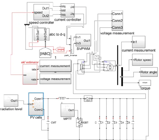
The total drive system is established and simulated in Matlab/Simulink environment by taking consideration of start-up situation. The model for the motor estimation system is shown in Fig. 2. The system contains the space vector pulse width modulation (SVPWM), current speed controller, EKF observer, and the MPPT based PV system. The parameters used to simulate the system are shown in Table I.
Fig. 2. Simulation diagram of sensorless speed control of PMSM by using EKF.
TABLE I. PARAMETERS OF THE PROPOSED SYSTEM.
Symbol Parameters Value
Rs [Ω] Stator resistance 2.125
Ls [H] Stator inductance 0.00116
J [kg x m2] Rotor inertia 0.03
λm [Wb] Rotor magnetic flux 0.387
P Number of pole pairs 6
IR [W/m2] Solar irradiance 1200
TMP [oC] Temperature 25
By comparing this study with other studies in the same field, e.g., utilizing the high frequency signal injection and the EKF to control the speed in very low and standstill regions [23], the proposed method can be deemed better because it eliminates the need of using a second method to control the speed in a very low-speed region. In other studies, it is claimed that adjusting the DC voltage will make the system work on the very low-speed level [24]. The main idea in this paper is instead of adjusting the voltage, the d-axis current is adjusted for the very low-speed ranges in the PMSMs supplied by MPPT based solar PV system. As shown in equation (1), motor speed depends on the voltage and current values in the system. The problem is that if the voltage level increases, it will decrease the accuracy of the rotor position estimator in low-speed regions [24]. For
example, it can be inferred from Fig. 3(a) and Fig. 3(b) that the motor speed deteriorates when solar system operates at an irradiance of 1200 W/m2 and outputs 470 V. While in
Fig. 4(c), when the system operates at an irradiance level of 600 W/m2, it outputs about 340 V and the speed estimator
successfully tracks the speed (Figs. 4(a) and 4(b)) in very low levels. Since, in the PV system, the DC voltage depends on the solar irradiance level, it is hard to control such a system with just adjusting the DC voltage level of the system. To solve this problem, instead of adjusting the DC voltage, Id current is set to a certain value (in this motor Id = 0.5) to control the very low-speed values. The value of d-axis current is found by using trial and error method and it should be small to avoid the saturation in the motor. The results of this method are shown in Fig. 5 and Fig. 6 for irradiation levels of 1200 W/m2 and 600 W/m2, respectively.
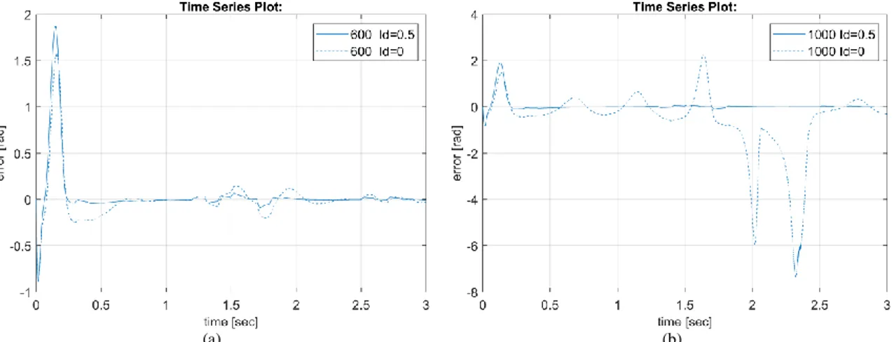
Also, by fixing the d-axis current, the error between real and estimated speed is reduced as shown in Fig. 7.
The system used in this paper is simulated in both low and high speeds to evaluate the validity of the proposed method to run the motor in the wide-speed range as shown in Figs. 3–7. The algorithm of EKF is implemented in the model by using the S function. The inputs of the S function are the currents and the voltages in stationary (α-β) reference frame. The outputs are the speed and the rotor position estimated values.
(a) (b)
(c) (d) Fig. 3. (a) – the measured and estimated speed for 1200 W/m2 (when I
d = 0); (b) – measured and estimated speed error; (c) DC voltage level at 1200 W/m2; (d) I-V and P-V characteristics showing MPPT operation.
(a) (b)
(c) (d) Fig. 4. (a) – the measured and estimated speed at 600 W/m2 (when I
d = 0); (b) – measured and estimated speed error; (c) DC voltage level at 600 W/m2; (d) I-V and P-V characteristics showing MPPT operation.
(a) (b)
(c) (d) Fig. 5. (a) – the measured and estimated speed at 1200 W/m2 (when I
d = 0.5); (b) – measured and estimated speed error; (c) DC voltage level at 1200 W/m2; (d) I-V and P-V characteristics showing MPPT operation.
(a) (b)
(c) (d) Fig. 6. (a) – the measured and estimated speed in wide range (when Id = 0.5 for low speed); (b) – measured and estimated speed error; (c) DC voltage level at 600 W/m2; (d) I-V and P-V characteristics showing MPPT operation.
(a) (b) Fig. 7. (a) – the measured and estimated speed error for 600 W/m2 (when I
d = 0 and Id = 0.5 for low speed); (b) – measured and estimated speed error for 1200 W/m2 (when I
d = 0 and Id = 0.5 for low speed).
Through the collected simulation results from PV system (Fig. 3(d), Fig. 4(d), Fig. 5(d), and Fig. 6(d)), we can notice that the MPPT system was able to find and track the maximum power point. It is also obvious that it was able to make the operating point of the system exactly at the MPP. Thus, the withdrawal of the energy from the solar panel was very close to the optimal. In this paper, the extracted power for three MPPT algorithms, which are perturbation & observation (P&O), Fuzzy Logic (FL) based algorithm, and IC algorithm, is presented. The obtained results are given in Table II. Although FL-based method gives slightly higher results, it was not preferred in this study due to its high computational complexity.
TABLE II. COMPARISONS OF THREE MPPT ALGORITHMS.
Irradiation level (W/m2) Temperature (oC) Maximum power for P&O algorithm (W) Maximum power for FL algorithm (W) Maximum power for IC algorithm (W) 1200 50 1492 1505 1499 1200 25 1735 1745 1741 1000 50 1267 1274 1270 1000 25 1481 1490 1486 800 50 991 1000 996 800 25 1198 1210 1205 600 50 749 755 751 600 25 790 800 796 V. CONCLUSIONS
This paper presents a new method that makes the EKF estimates very low speeds of PMSM fed by solar PV system. This method reduces the complexity of controlling the PMSM in a wide speed range, which makes the estimating system work perfectly on both the FPGA and DSP systems. Also, by fixing the d-axis current in the system, it will help to reduce the errors that happened between the estimated and the real speed, especially when the motor uses high input voltages. This method will be suitable for pumping systems and electric vehicles, which will reduce the cost and size of the motor hence, increasing the utilization of PMSM in other applications. In addition, with the view to optimizing the power production from solar panels, Incremental Conductance approach based MPPT
was introduced. Simulation results showed that the IC algorithm has a good tracking ability. It was able to obtain maximum power in terms of variable conditions and increased stabilization of load.
CONFLICTS OF INTEREST
The authors declare that they have no conflicts of interest. REFERENCES
[1] L. Xiaoquan, L. Heyun, and H. Junlin, “Load disturbance observer-based control method for sensorless PMSM drive”, IET Elect. Power
Appl., vol. 10, no. 8, pp. 735–743, 2016. DOI:
10.1049/iet-epa.2015.0550.
[2] N. K. Quang, D. Q. Vinh, N. D. That, and Q. P. Ha, “Observer-based integral sliding mode control for sensorless PMSM drives using FPGA”, in Proc. of 2013 International Conference on Control,
Automation and Information Sciences (ICCAIS 2013), 2013. DOI:
10.1109/ICCAIS.2013.6720557.
[3] S. Bolognani, O. Roberto, and Z. Mauro, “Sensorless full-digital PMSM drive with EKF estimation of speed and rotor position”, IEEE
Transactions on Industrial Electronics, vol. 46, no. 1, pp. 184–191,
1999. DOI: 10.1109/41.744410.
[4] H. Zhu, X. Xiao, and Y. Li, “A simplified high frequency injection method for PMSM sensorless control”, in Proc. of Power Electronics
and Motion Control Conference (IPEMC 2009), 2009. DOI:
10.1109/IPEMC.2009.5157420.
[5] T. Kereszty, V.-M. Leppanen, and J. Luomi, “Sensorless control of surface magnet synchronous motors at low speeds using low-frequency signal injection”, in Proc. of IECON’03, Nov. 2003, pp. 1239–1243. DOI: 10.1109/IECON.2003.1280230.
[6] V.-M. Leppanen and J. Luomi, “Observer using low-frequency injection for sensorless induction motor control – parameter sensitivity analysis”, IEEE Transactions on Industrial Electronics, vol. 53, no. 1, Feb. 2006, pp. 216–224. DOI: 10.1109/TIE.2005.862293.
[7] R. Risfendra, Y.-Sh. Kung, and L.-Ch. Huang, “Design and digital hardware implementation of a sensorless controller for PMSM drives using LF signal injection and EKF”, in Proc. of International
Conference on Applied System Innovation (ICASI), 2017. DOI:
10.1109/ICASI.2017.7988132.
[8] H. M. Kojabadi and L. Chang, “Sensorless PMSM drive with MRAS-based adaptive speed estimator”, in Power Electronics Specialists
Conference, 2006, pp. 1–5. DOI: 10.1109/pesc.2006.1712038.
[9] B. Jiang, “A novel algorithm based on EKF to estimate rotor position and speed for sensorless PMSM drivers”, in Proc. of International
Conference on Information Engineering and Computer Science (ICIECS 2009), 2009, pp.1–4. DOI: 10.1109/ICIECS.2009.5362756.
[10] N. Karami, N. Moubayed, and R. Outbib, “General review and classification of different MPPT Techniques”, Renewable and
Sustainable Energy Reviews, vol. 68, Part 1, 2017, pp. 1–18. DOI:
10.1016/j.rser.2016.09.132.
[11] T. Esram and P. L. Chapman, “Comparison of photovoltaic array maximum power point tracking techniques”, IEEE Trans. Energy
10.1109/TEC.2006.874230.
[12] S. Jain, A. Vaibhav, and L. Goyal, “Comparative analysis of MPPT techniques for PV in domestic applications”, in Proc. of 2014 6th
IEEE Power India International Conference (PIICON), Delhi, 2014,
pp. 1–6. DOI: 10.1109/POWERI.2014.7117636.
[13] A. Chouksey, S. Awasthi, and S. K. Singh, “Fuzzy cognitive network-based maximum power point tracking using a self-tuned adaptive gain scheduled fuzzy proportional integral derivative controller and improved artificial neural network-based particle swarm optimization”, Fuzzy Sets and Systems, 2019 (in Press, Corrected Proof). DOI: 10.1016/j.fss.2019.02.007.
[14] A. Harrag and S. Messaltic, “IC-based variable step size neuro-fuzzy MPPT improving PV system performances”, Energy Procedia, vol. 157, pp. 362–374, 2019. DOI: 10.1016/j.egypro.2018.11.201. [15] H. Li, D. Yang, W. Su, J. Lü, and X. Yu, “An overall distribution
particle swarm optimization MPPT algorithm for photovoltaic system under partial shading”, IEEE Transactions on Industrial Electronics, vol. 66, no. 1, pp. 265–275, Jan. 2019. DOI: 10.1109/TIE.2018.2829668.
[16] S. Padmanaban, N. Priyadarshi, J. B. Holm-Nielsen, and M. Sagar Bhaskar, “A novel modified sine-cosine optimized MPPT algorithm for grid integrated PV system under real operating conditions”, IEEE
Access, vol. 7, pp. 10467–10477, 2019. DOI: 10.1109/ACCESS.2018.2890533.
[17] J. Mapurunga Caracas, G. De Carvalho Farias, L. Moreira Teixeira, and L. De Souza Ribeiro, “Implementation of a high efficiency, high-lifetime, and low cost converter for an autonomous photovoltaic water pumping system”, IEEE Transactions on Industry Applications, vol. 50, no. 1, pp. 631–641, Jan.-Feb. 2014. DOI: 10.1109/TIA.2013.2271214.
[18] B. A. Essalam and K. Mabrouk, “Grid-connected modeling, control
and simulation of single phase two-level photovoltaic power generation system coupled to a permanent magnet synchronous”, in
Proc of International Workshop on Systems, Signal Processing and their Applications (WOSSPA), Tipaza, 2011, pp. 29–34. DOI:
10.1109/WOSSPA.2011.5931500.
[19] F. Mayssa, F. Aymen, and S. Lassaâd, “Influence of photovoltaic DC bus voltage on the high speed PMSM drive”, in Proc. of IECON 2012 - 38th Annual Conference on IEEE Industrial Electronics Society,
Montreal, QC, 2012, pp. 4489–4494. DOI:
10.1109/IECON.2012.6389462.
[20] S. Khani, L. Mohammadian, S. H. Hosseini, and S. Ghasemzadeh, “Design and control of fully parallel embedded Z-source inverters based flexible photovoltaic systems for grid power quality improvement under distorted condition”, in Proc. of 2013 21st
Iranian Conference on Electrical Engineering (ICEE), Mashhad,
2013, pp. 1–7. DOI: 10.1109/IranianCEE.2013.6599896.
[21] R. Belu, “Power Electronics and Controls in Solar Photovoltaic Systems”, Research Methods: Concepts, Methodologies, Tools, and
Applications, 2015. DOI: 10.4018/978-1-4666-7456-1.ch087.
[22] S. Soltani and M. J. Kouhanjani, “Fuzzy logic type-2 controller design for MPPT in photovoltaic system”, in Proc. of 2017 Conference on
Electrical Power Distribution Networks Conference (EPDC),
Semnan, 2017, pp. 149–155. DOI: 10.1109/EPDC.2017.8012756. [23] X. Wen, Y. Zhang, and Y. Lin, “Observability analysis and
EKF-based sensorless control of permanent magnet synchronous machine”, in Proc. of 2017 36th Chinese Control Conference (CCC), Dalian, 2017, pp. 151–156. DOI: 10.23919/ChiCC.2017.8027336.
[24] S. Gu, F. He, and H. Zhang, “Study on extend Kalman filter at low speed in sensorless PMSM drives”, in Proc. of 2009 International
Conference on Electronic Computer Technology, Macau, 2009, pp.