Non-ideal cloaking based on Fabry-Perot
resonances in single-layer high-index
dielectric shells
A. E. Serebryannikov,1,* P. V. Usik,2 and Ekmel Ozbay1
1Nanotechnology Research Center-NANOTAM, Department of Physics, Department of Electrical and Electronics Engineering, Bilkent University, 06800 Ankara, Turkey
2 Institute of Radio Astronomy, National Academy of Sciences of Ukraine, 61085 Kharkiv, Ukraine * [email protected]
Abstract: Strong reduction of the scattering cross section is obtained for
subwavelength dielectric and conducting cylinders without any magnetism for both TE and TM polarizations. The suggested approach is based on the use of Fabry-Perot type radial resonances, which can appear in single-layer, high-ε, isotropic, and homogeneous shells with the properly chosen parameters. Frequencies of the minima of the scattering cross section, which are associated with the cloaking, typically depend on whether TE or TM polarization is considered. In some cases, positive-ε and large-negative-ε objects can be cloaked. In other cases, non-ideal multifrequency cloaking can be realized.
©2009 Optical Society of America
OCIS codes: (260.2110) Electromagnetic optics; (260.5740) Resonance; (290.5839) Scattering, invisibility; (050.2230) Fabry-Perot.
References
1. J. B. Pendry, D. Schurig, and D. R. Smith, “Controlling electromagnetic fields,” Science 312(5781), 1780–1782 (2006).
2. D. Schurig, J. J. Mock, B. J. Justice, S. A. Cummer, J. B. Pendry, A. F. Starr, and D. R. Smith, “Metamaterial electromagnetic cloak at microwave frequencies,” Science 314(5801), 977–980 (2006).
3. S. A. Cummer, B.-I. Popa, D. Schurig, D. R. Smith, J. Pendry, M. Rahm, and A. Starr, “Scattering theory derivation of a 3D acoustic cloaking shell,” Phys. Rev. Lett. 100(2), 024301 (2008).
4. N.-A. P. Nicorovici, G. W. Milton, R. C. McPhedran, and L. C. Botten, “Quasistatic cloaking of two-dimensional polarizable discrete systems by anomalous resonance,” Opt. Express 15(10), 6314–6323 (2007).
5. N.-A. P. Nicorovici, R. C. McPhedran, S. Enoch, and G. Tayeb, “Finite wavelength cloaking by plasmonic resonance,” N. J. Phys. 10(11), 115020 (2008).
6. A. Alù, and N. Engheta, “Plasmonic materials in transparency and cloaking problems: mechanism, robustness, and physical insights,” Opt. Express 15(6), 3318–3332 (2007).
7. A. Alù, and N. Engheta, “Effects of size and frequency dispersion in plasmonic cloaking,” Phys. Rev. E Stat. Nonlin. Soft Matter Phys. 78(4), 045602 (2008).
8. P. Alitalo, O. Luukkonen, J. Mosig, and S. Tretyakov, “Broadband cloaking with volumetric structures composed of two-dimensional transmission-line networks,” Microw. Opt. Technol. Lett. 51(7), 1627–1631 (2009). 9. P. Alitalo, F. Bongard, J.-F. Zurcher, J. Mosig, and S. Tretyakov, “Expermental verification of broadband
cloaking using a volumetric cloak composed of periodically stacked cylindrical transmission-line networks,” Appl. Phys. Lett. 94(1), 014103 (2009).
10. A. E. Serebryannikov, and E. Ozbay, “Multifrequency invisibility and masking of cylindrical dielectric objects using double-positive and double-negative metamaterials,” J. Opt. A, Pure Appl. Opt. (to appear).
11. N. M. Litchinitser, and V. M. Shalaev, “Photonic metamaterials,” Laser Phys. Lett. 5(6), 411–420 (2008). 12. D. P. Gaillot, C. Croënne, and D. Lippens, “An all-dielectric route for terahertz cloaking,” Opt. Express 16(6),
3986–3992 (2008).
13. F. Bilotti, S. Tricarico, and L. Vegni, “Electromagnetic cloaking devices for TE and TM polarizations,” N. J. Phys. 10(11), 115035 (2008).
14. S. Tusseau-Nenez, J.-P. Ganne, M. Maglione, A. Morell, J.-C. Niepce, and M. Pate, “BST ceramics: effect of attrition milling on dielectric properties,” J. Eur. Ceram. Soc. 24(10-11), 3003–3011 (2004).
15. A. V. Kildishev, and E. E. Narimanov, “Impedance-matched hyperlens,” Opt. Lett. 32(23), 3432–3434 (2007). 16. A. Alù, and N. Engheta, “Multifrequency optical invisibility cloak with layered plasmonic shells,” Phys. Rev.
1. Introduction
The theory and experimental verification of invisibility cloaks for dielectric and conducting objects have been the focus of interest for the last three years. Several approaches have been suggested, which include those based on transformational optics [1–3], localized anomalous resonance [4,5], plasmonic cloaking [6,7], and transmission-line networks [8,9]. Recently, the cloaking mechanism that is based on the Fabry-Perot type radial resonances in metamaterial shells has been suggested [10]. The possibility of a substantial reduction of the scattering cross section without magnetism is very intriguing, especially for optical cloaks. It has been shown that the transformational optics approach does not require any magnetism, if magnetic field is polarized along the cloak axis [11]. The terahertz cloak based on the concentric layers of ferroelectric rods, which show a strong magnetic resonance in line with Mie theory, has been studied in [12]. The microwave cloak based on the plasmonic cloaking approach has been proposed in [13], which allows making a dielectric object invisible for TE and TM polarizations simultaneously. However, magnetism is required in this case.
In the present paper, we will demonstrate the existence of the Fabry-Perot radial resonances in purely dielectric, isotropic, homogeneous, high-index, single-layer shells, and their potential in cloaking of dielectric and conducting objects. It is shown that at least a non-ideal cloaking can be achieved for the both polarizations, but at different frequencies and geometrical parameters. Our heuristic approach is based on the analogy between the zero-refection regime in conventional planar Fabry-Perot resonators and the expected regime of (nearly) zero scattering cross section in the cylindrical Fabry-Perot resonators with the same distance between the “mirrors” (interfaces) and the same filling material. The emphasis will be put on the ranges of variation of frequency and permittivity of the coated cylinder, for which significant reduction of the scattering cross section can be achieved due to the coating.
2. Background
According to the classical theory of planar Fabry-Perot resonators, the multiple zeros of the refection coefficient appear at nkDcosθ = πm where D, n, and θ are the distance between the mirrors, the refraction index of the filling medium, and the angle of incidence, respectively, and m = 1,2,… . An expected necessary condition for achieving zero “reflection” in the cylindrical case is that λs <<r where λs is the wavelength in the shell material and r is the
radius of the cylinder to be cloaked. Finding the optimal parameters of the shell is beyond the scope of the present paper.
As an example of proper materials for the shell, one should mention polar dielectrics at terahertz frequencies and ferroelectrics at microwave frequencies [14], as well as Drude-Lorentz composites in a wide frequency range. The range of variation of the permittivity of the coating shell is chosen by taking into account the materials that are available at optical and microwave frequencies. In fact, each frequency value in the plots presented corresponds to a different material, since frequency dispersion is not taken into account here.
The normalized cross section is calculated as
∑ = ∞ −∞ = − n n c kR) 1 2 ( σ ,
where cn is the nth-order diffraction coefficient. The actual values of σ can slightly differ from
those shown in the figures presented, owing to the series reduction. However, as follows from the obtained numerical results, an increase of maxn in the reduced series only leads to a very slight shift of the extrema. To obtain cn, the conventional analytical approach is used, which is
based on the Fourier-Bessel series and the boundary conditions for the tangential field components.
3. Results and discussion
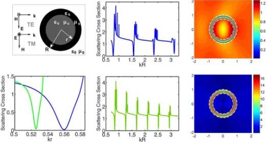
Figure 1 shows the general geometry of the problem and typical far- and near-field features arising in scattering on the single-layer high-ε empty shells. The indices c and s at ε and µ in
the upper left plot stand for the core and shell, respectively. One can clearly see in the middle plots that the multiple minima of σ are nearly equidistant. In the upper middle plot, they are located at kR = 0.7835, 1.566, 2.3453, and 3.126, corresponding to ξ = εck(R−r)≈πm at m
= 1, 2, 3, and 4, respectively. In the lower middle plot, the minima appear at kR = 0.841, 1.2615, 1.6815, 2.1005, 2.5206, and 2.9403, which correspond to ξ ≈πm at m = 2, 3, 4, 5, 6, and 7. The obtained values of ξ/(πm) vary monotonously from 1.0077 at m = 1 to 1.0051 at
m = 4 in the upper middle plot, and from 1.0039 at m = 2 to 1.0028 at m = 7 in the lower middle plot. These examples show that the curvilinearity of the “mirrors” exerts a slight effect on the minima locations. In contrast, it affects the deviation of the σ-values from zero at the minima, as well as the number and locations of the maxima. Hence, the standard theoretical framework for the Fabry-Perot etalon at θ = 0 can be used to predict the location of the minima of σ for high-index dielectric ring shells, at least in the subwavelength case.
Fig. 1. Upper left plot: general geometry of the problem; Middle plots: scattering cross section at εs = 200 and R/r = 1.4 (upper), and εs = 400 and R/r = 1.6 (lower), εc = µs = µc = 1, TM
polarization; Lower left plot: fragment of the upper middle plot (blue line) and lower middle plot (green line); Right plots: modulus of the axial (upper) and azimuthal (lower) field components at kR = 1.566 and same remaining parameters as in the upper middle plot.
The smallest σ-values are observed at the minima for rather small kR and, therefore, for small m. It follows from the obtained simulation results that σmax/σmin>500 can be achieved,
where σmax and σmin mean the values of σ, which correspond to the neighboring maximum and
minimum. The larger R/r and/or εs, i.e., the denser minima of σ, the narrower the
corresponding resonances are, as is shown in the lower left plot in Fig. 1. It is noteworthy that similar but wider Fabry-Perot type resonances can be obtained, for example, for a shell made of a matched metamaterial (εs = µs) [10], while keeping the same index of refraction.
Therefore, the less sharp minima can be obtained for the price of using a material with magnetic properties. In contrast, no magnetism is required for the considered theoretical performances. Typical near-field features are demonstrated in the right plots in Fig. 1. The dashed lines (circles) correspond to the radii R and r. A slight deviation of |Ez| from 1 takes
place outside the shell, while
σ
=6×10⁻³. Inside the shell, behavior of |Ez| is in agreement withthat expected to appear according to the used analogy with planar Fabry-Perot resonators. Strong enhancement of the |Hφ| within the shell occurs, so that the alternating ranges of the
dominant contribution of either electric or magnetic field can be distinguished. Similar far-field features are observed in the case of TE polarization. The deep minima of σ have also been observed at smaller εs than in Fig. 1, e.g., at εs = 30, 50, and 70. For example, σ = 0.013
for practical purposes, since a wider choice of possible performances, lower losses, and wider resonance curves at the minima are expected to occur.
Figure 2 demonstrates the effect of a relatively small variation of the radii of the empty shell on σ and effect of the shell on the phase map for the parameters from Fig. 1. The used variation of R/r results in that the minima of σ are shifted but do not disappear. The wider minima, the better it would be from the point of view of possible fabrication tolerances. For the considered parameters, strong reduction of σ remains at a fixed frequency, at least if R/r differs from its desired value by no more than 0.3%. Comparing the middle and right plots in Fig. 2, one can see that the phase values of the axial field component outside the shell weakly differ from those in free space. The red and blue half-rings in the right plot correspond to the antiphase fields, which appear within the shell due to the peculiar behavior of the Fabry-Perot resonance field. Neglecting by the term of π in the phase values within the above-mentioned half-rings, one could see that the phase map within most part of the shell can be considered as a continuation of that within the adjacent domains of the shell, core, and surrounding free space.
Fig. 2. Left plot: scattering cross section at εs = 200 and εc = µs = µc = 1 for several values of R/r, TM polarization; solid yellow, red, blue, green, and cyan lines correspond to R/r = 1.39, 1.395, 1.4, 1.405, and 1.41; dashed and dotted blue lines correspond to the outer-to-inner-radii ratio R1/r1 = 1.4 where R1 = ηR and r1 = ηr with η = 1.01 and η = 0.99, respectively; Middle plot: phase map of the axial component in free space (εs = εc = µs = µc = 1) at kR = 1.566; Right
plot: phase map corresponding to |Ez| in the upper right plot in Fig. 1.
Let us now consider whether the above-described features remain while placing a positive-ε or negative-positive-ε cylinder of radius r inside the shell. This case should correspond to the situation when a planar Fabry-Perot resonator is located between two half-spaces, which show different values of ε. The minima of σ are expected to remain at least if εc<<εs, but it is not
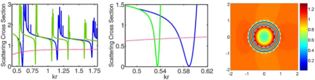
clear a priori whether such small σ -values can be achieved that the obtained reduction can be still associated with the cloaking. First, we place the intermediate-negative-ε cylinder inside the shell. Figure 3 shows an example for TM polarization. Although the range of kr variation, within which deep minima can appear, is now narrower than that at εc = 1 (compare to Fig. 1),
parameter values can be selected, at which σc/σnc<<1, where σc and σnc mean the scattering
cross sections for the coated and non-coated cylinders, respectively. In Fig. 3, σc/σnc≈0.021 at kr = 0.59 in the case shown by the blue line, and σ /σ ≈7.1×10⁻⁴
nc c at kr = 0.535 and 138 . 0 /σ ≈
σc nc at kr = 0.798 in the case shown by the green line. Hence, either non-ideal or
nearly ideal cloaking can be obtained at least for the subwavelength plasmonic cylinders with 2 /r λ≈0.17...0.19.
One can see that the field behavior in the shell keeps the features that are typical for the Fabry-Perot type resonances. The minima remain to be nearly equidistant. Cylinders with smaller εc can be cloaked within the same kr range. For example, σc = 0.0148 at kr = 0.533, εc
= −15.2, εs = 900, µs = µc = 1, and R/r = 1.4. In the case of TE polarization, near-zero σ can
also be obtained, but for larger εc than in the case of TM polarization. For example, σc = 0.018
at εc = −2.8 and kr = 0.529, and σc = 0.095 at εc = −5.8 and kr = 0.531, and the same remaining
parameters as in the previous example. Note that in the case shown in Fig. 3 by the green line, a nearly zero σ can be obtained at two kr-values simultaneously. Two or more such values
Fig. 3. Left plot: scattering cross section at εs = 200, εc = −10.2, and R/r = 1.4 (blue line), εs =
400, εc = −10.2, and R/r = 1.6 (green line), and εs = 1 and εc = −10.2 (red line); Middle plot:
fragment of the left plot; Right plot: modulus of the axial field at kR = 0.856 (kr = 0.535, m = 2) and same remaining parameters as in case shown by green line; µs = µc = 1, TM polarization.
have also been observed for other theoretical performances, e.g., for εs = 200, 400, 900 and R/r = 2.4, and εs = 900 and R/r = 2. In turn, a wideband enhancement of σ can be achieved due
to the coating beyond the narrow ranges of the cloaking. It is expected that some interconnects can exist between our approach and the theory of scattering cancellation in plasmonic cloaking [6,7] atsgn(εc−1)≠sgn(εs−1), as in Fig. 3. Fig. 4 demonstrates the effect of R/r on the kR-dependence of σ and effect of the core and shell on the phase map. The features observed in Fig. 2 remain. In particular, the values of σ at the minima in the left plot in Fig. 4 weakly depend on the used variation of R/r. Here, they are less than 4
8 10× − . Hence, one can decide between multiple pairs of the values (kR,R/r), while the extent to which σ is reduced is kept. The phase map outside the shell slightly differs from that in free space.
Fig. 4. Left plot: scattering cross section at εs = 400, εc = −10.2, and µs = µc = 1 for several
values of R/r, TM polarization; solid yellow, red, blue, green, and cyan lines correspond to R/r = 1.58, 1.59, 1.6, 1.61, and 1.62; dashed and dotted blue lines correspond to the outer-to-inner-radii ratio R1/r1 = 1.6 where R1 = ηR and r1 = ηr with η = 1.01 and η = 0.99, respectively; Middle plot: phase map in free space (εs = εc = µs = µc = 1) at kR = 0.856; Right plot: phase map
for the field shown in the right plot in Fig. 3.
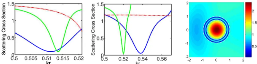
It is shown in Fig. 5 that σ can be significantly reduced for subwavelength dielectric cylinders by using the Fabry-Perot radial resonances, even at rather large εc, e.g., at εc>10.
Here, we consider the resonances with m = 1 and m = 2, for which the smallest values of
σ
σc/ nc were achieved. In particular, in the left plot, σc/σnc≈0.07 at kr = 0.511 in case
shown by the blue line and σc/σnc≈0.073 at kr = 0.5135 in case shown by the green line. In the middle plot, σc/σnc≈0.049 at kr = 0.538 in case shown by the blue line and
042 . 0 /σ ≈
σc nc at kr = 0.52 in case shown by the green line. The range of kr variation, where
significant reduction of σ is possible, can be extended toward larger values for smaller εc, e.g.,
for εc = 2.5.
Compare the locations of the minima for the cases shown in Figs. 1, 3, and 5 by a blue line (εs = 200, R/r = 1.4) in the vicinity of kr = 0.56. One can see that placing a positive-ε or
Fig. 5. Left plot: scattering cross section at εs = 200 (blue line), εs = 900 (green line), and εs = 1
(red line), εc = 10.2 and R/r = 1.4; Middle plot: same as left plot but for εc = 5.8; Right plot:
modulus of the axial field at kR = 0.719 (kr = 0.5136, m = 2) and the same remaining parameters as in the case shown in left plot by green line; µs = µc = 1, TM polarization.
Fig. 6. Left plot: scattering cross section at εs = 900, εc = 10.2, and µs = µc = 1 for several values
of R/r, TM polarization; solid yellow, red, blue, green, and cyan lines correspond to R/r = 1.39, 1.395, 1.4, 1.405, and 1.41; dashed and dotted blue lines correspond to the outer-to-inner-radii ratio R1/r1 = 1.4 where R1 = ηR and r1 = ηr with η = 1.01 and η = 0.99, respectively; Middle plot: phase map in free space (εs = εc = µs = µc = 1) at kR = 0.719; Right plot: phase map for the
field shown in the right plot in Fig. 5.
respectively. In particular, ξ/(πm) = 1.061 in the middle plot in Fig. 3, and ξ/(πm) = 0.921 and 0.969 in the left and middle plots in Fig. 5, so that ξ>ξes at εc<0 and ξ<ξes at εc>0, where es
stands for the empty shell. The observed shifts qualitatively coincide with the theory of perturbations of the cavity resonators. However, the enhancement of the field in the core looks, at first glance, like an argument against using this theory. Finding appropriate interconnects between the Fabry-Perot and cavity resonator perturbation theories, and perhaps other theories will be the subject of future studies. The field concentration due to the core resonances is a feature that distinguishes our cloaking approach from that based on the transformational optics [1–3]. It could be used, for example, for harvesting solar energy, provided that a proper optimization is performed. Figure 6 demonstrates the effect of R/r on the kR-dependence of σ and effect of the core and shell on the phase map. The above-discussed features remain here. In particular, the used variation of R/r does not allow one achieving significant variation of σ at the minimum. The phase map outside the shell differs from that in free space much stronger than in Figs. 2 and 4, corresponding to larger values of σ. However, if the distance from the shell is δ ≥R, the phase maps in the cases shown in the middle and right plots in Fig. 6 tend to coincide.
Consider now scattering of TE-polarized plane wave by the coated and non-coated dielectric cylinders. In fact, minima of σ may appear for a coated cylinder for TE and TM polarizations at nearly the same frequency, at least for εc<<εs and relatively small kr and m.
However, for the non-coated cylinders and TE polarization, kr-values starting from which 1
σ ∝ are larger than for TM polarization. Therefore, reduction of σ is required at larger values of kr, which still correspond to the subwavelength cylinders. On the other hand, it could be difficult to obtain small values of σc/σnc at the minima for this kr-range for TM
Fig. 7. Left plot: scattering cross section at εs = 900 (blue line) and εs = 1 (red line), εc = 5.8 and R/r = 2; Middle plot: fragment of the left plot; Right plot: modulus of the axial field at kR = 2.093 (kr = 1.0465, m = 10) and the same remaining parameters as in the case shown by a blue line; µs = µc = 1, TE polarization.
examples, parameters are chosen so that strong reduction of σ occurs for TE polarization, while behavior of σ for TM polarization is not taken into account. Figure 7 shows the strong reduction of σ for the dielectric cylinder with εc = 5.8 and λ/ 2r≈ . Now, 3 σc/σnc≈0.072
and ξ/(πm) = 0.9993 at kr = 1.0465. The corresponding field pattern is also presented, showing the Fabry-Perot type radial dependence, i.e., the alternating and equidistant minima and maxima in the shell. Contrary to the field patterns for TM polarization in Figs. 1, 3, and 5, the focusing appears within the shell near φ = 0 and φ = π (φ is measured from the abscissa axis), showing radial modulation of the field. This regime can be considered in some sense as inverse to the imaging beyond the diffraction limit, which has recently been demonstrated, in particular, for the impedance matched cylindrical hyperlens [15]. This is so because the incident wave leads in our case to the appearance of two focuses, while the distance between them is d<λ/2.
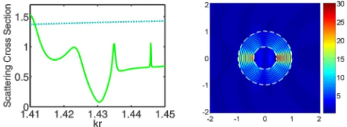
Fig. 8. Left plot: scattering cross section at εs = 200 (green line) and εs = 1 (blue line), εc = 5.8,
and R/r = 2.4; Right plot: modulus of the axial field at kR = 3.433 (kr = 1.4304, m = 9) and the same remaining parameters as in case shown in left plot by green line; µs = µc = 1, TE
polarization.
Similar near- and far-field effects can be achieved even for a slightly subwavelength cylinder and smaller εs, see Fig. 8. Here, σc/σnc≈0.056 at kr = 1.4304. Field enhancement
in the shell is a typical feature of the cloaking regime for TE polarization, which also appears at small m. Note that in Fig. 7 we obtain σnc/σc>10 at several kr-values, so that the non-ideal
multifrequency cloaking is achievable by using purely dielectric shells, that is distinguished from the approaches suggested earlier [10,16]. Finally, we present two examples, which show that a significant reduction of σ can be obtained in some cases by covering the inner cylinder with a dielectric shell that has a much smaller εs than in the previous figures. In Fig. 9, an
example is presented for εs = 30. Here, σc/σnc≈0.063 and 0.027 for the minima of σ in the
left and right plots, respectively. Note that the reduction of σ is obtained now at smaller εs and
εc, within the same ranges of kr variation as in Figs. 2-8. Based on the simulation results, one
might expect that a further decrease of the thickness and permittivity of the shell is possible. Our most recent results show that σ<0.09 can be obtained for εc = 2.8 even at εs = 15, e.g., in
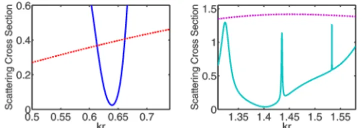
Fig. 9. Left plot: scattering cross section at εs = 30 (blue line) and εs = 1 (red line), εc = 2.8, R/r
= 2, TM polarization; Right plot: scattering cross section at εs = 30 (blue line) and εs = 1 (violet
line), εc = 2.8, R/r = 1.4, TE polarization; µs = µc = 1. 4. Conclusions
To summarize, we studied scattering of plane waves by dielectric and conducting cylinders, which are moderately or weakly subwavelength and coated with a single-layer high-ε dielectric shell. It is shown that substantial reduction of the scattering cross section is possible due to Fabry-Perot type radial resonances that appear in the coating shell. The location of the corresponding frequencies can be estimated with a high accuracy by using a simple analytical model of the conventional planar Fabry-Perot resonators, so that the used analogy between the zero reflection regime in the planar resonators and near-zero scattering cross section regime in the cylindrical resonators is quite justified. The obtained results demonstrate that magnetism is not required in order to cloak small dielectric and conducting cylinders at both TE and TM polarizations. However, frequencies and geometrical parameters, at which cloaking is achieved, depend in the considered examples on the choice of polarization. The observed near- and far-field features allow one expecting that the suggested structures can also be used for the concentration and focusing of electromagnetic waves, and for the scattering enhancement.
Acknowledgments
This work was supported by the European Union under the projects PHOME and EU-ECONAM, and TUBITAK under the Project Nos. 106E198, 107A004, and 107A012. A. S. thanks TUBITAK for the partial support provided for this work in the framework of the Visiting Scientist Fellowship Program. E. O. also acknowledges partial support from the Turkish Academy of Sciences.