R E S E A R C H A R T I C L E
Optically reconfigurable planar
monopole antenna for cognitive
radio application
Abdul Ali
1|
Kagan Topalli
2|
Mehrab Ramzan
3|
Muhammad Alibakhshikenari
1|
Talha Masood Khan
4|
Ayhan Altintas
5,6|
Paolo Colantonio
11
Department of Electronics Engineering, University of Rome Tor Vergata, Rome, Italy
2
TUBITAK Space Technologies Research Institute, Ankara, Turkey
3
Chair of RF Engineering, Communication Laboratory, TU Dresden, Germany
4
UNAM-Institute of Materials Science and Nanotechnology, Bilkent University, Ankara, Turkey
5
Department of Electrical and Electronics Engineering, Bilkent University, Ankara, Turkey
6
Communication and Spectrum Management Research Center (ISYAM), Bilkent University, Ankara, Turkey
Correspondence
Abdul Ali, Department of Electronics Engineering, University of Rome Tor Vergata, Rome, 00133, Italy.
Email: [email protected] Funding information
H2020 ITN CELTA, Grant/Award Number: 675683
Abstract
Frequency reconfigurable antenna is one of the important elements needed for cognitive radio application. Such antenna can be designed using highly resistive (HR) sili-con (Si) operating as an optical switch. This letter pre-sents a novel frequency reconfigurable planar monopole antenna suitable for cognitive radio application. The antenna is designed using HR Si working as an optical switch. The main idea behind the design of antenna is the redistribution of surface current on the antenna while changing the state of Si switches optically from high resistance to low resistance. The antenna is highly com-pact and uses only two switches for multiband reconfi-guration. It is switchable on 1.9 GHz, 2.75 GHz, 3.7
GHz, 4.1 GHz, 4.6 GHz, 4.8 GHz, and 7.6 to 11 GHz frequency bands. Simulated and measured results are pre-sented for the antenna. To the best of authors knowledge, this is the first multiband optically reconfigurable planar monopole antenna.
K E Y W O R D S
cognitive radio, high-resistive (HR) silicon, low-resistive (LR) silicon, multiband, optical excitation, planar monopole antenna, reconfigurable
1
| I N T R O D U C T I O N
Reconfigurable antennas are type of smart antennas which can change their characteristics dynamically such as fre-quency, polarization, radiation pattern, and main beam direc-tion. Many single-function antennas working on different frequencies can be replaced by reconfigurable antennas thus reducing size and overall cost. Reconfigurable antennas are highly desirable for cognitive radio application, where they can switch their operating frequency dynamically to make use of any available channel.1,2
Reconfigurable antenna in its basic form contains a switch and reconfigurable element. The two parts of the antenna are connected in such a way that the former can change the characteristics (frequency, polarization, or main beam direction) of the antenna dynamically. The antenna works on one particular frequency when the switch is inac-tive (OFF); however, if the switch is activated (ON), then it works on a different frequency. The design of switch and its location on the antenna is critical as it can affect the perfor-mance of the latter.3–20 Therefore, it is important to make sure that the switch does not affect the performance of the antenna.
Reconfigurable antennas based on nonoptical and optical switches are reported in References 4–13 and 14–20, respec-tively. Optical switches are preferred over nonoptical switches in designing reconfigurable antennas. Unlike non-optical switches, they are fast and do not interfere parasiti-cally with the radiation characteristics of the antenna.14–20
Most of the optically reconfigurable antennas reported in literature are tuned in two or three frequency bands.14–20For instance, in References 14,15, the length of the printed dipole is dynamically increased with the help of two silicon (Si) switches to make the antenna frequency and polarization
DOI: 10.1002/mop.31678
agile. The authors in Reference 16 have integrated broad-band printed antenna with defected microstrip structure (DMS) band-pass filter to make its frequency reconfigurable without changing the dimensions of the antenna. In Refer-ence 17, Franklin array antenna is made reconfigurable using laser diode. In Reference 18, three Si switches are used to change the effective stub impedance seen by the patch antenna using low-power level from the optical source for frequency tuning. Another frequency agile antenna is reported in Reference 19 that uses high-power laser source. All these optically reconfigurable antennas work maximum in three frequency bands, and some of them require powerful laser source for switching operation.
In this letter, a novel optically frequency reconfigurable planar monopole antenna is presented for cognitive radio application. The antenna design adopts two Si samples each behaving as an optical switch. The characteristics of the Si samples are reported in Reference 3. Unlike previously reported reconfigurable antennas in literature, the antenna here is compact and switchable on multiband frequencies using only two Si switches. The prototype of the antenna is validated by full-wave EM simulation and measured results. A good agreement is found between full-wave EM simula-tion and measured results. In future, this letter could help engineers in designing various reconfigurable RF and micro-wave circuits for various applications.
2
| D E S I G N O F R E C O N F I G U R A B L E
M O N O P O L E A N T E N N A
Reconfigurable antenna is the core element of cognitive radio. Typically, cognitive radio consists of ultra wideband (UWB) antenna and reconfigurable antenna. The UWB antenna senses the channel then depending on its availability the reconfigurable antenna switches its operating frequency according to it.1,2
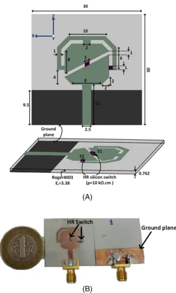
For cognitive radio application, we developed a novel optically frequency reconfigurable monopole antenna using the experimental results of Si with different charge carrier concentration as reported in Reference 3. The main idea behind the design of antenna is the redistribution of surface current on the antenna while changing the state of Si switches optically from high resistance to low resistance. Figure 1A illustrates the structure along with necessary geo-metrical parameters of the reconfigurable monopole antenna. The antenna consists of two regions, feeder line connected to a lower rounded triangle, and an upper rounded triangle. The two triangles are connected via two highly resistive (HR) Si switches (S1 and S2). The first switch (S1) directly connects the two regions from the middle of antenna, whereas the second switch (S2) connects the right side of lower triangle via strip to the top of the upper triangle in such a way to make crown-like shape. The advantage regarding such shape arrangement is the overall small size
and multiband reconfiguration of the antenna. Reconfigur-ability is achieved by changing the two switch positions in ON, OFF fashion which causes the surface current to redis-tribute on the antenna through different paths. Thus, looking from the feed point, the antenna can see different effective lengths. The size and resistivity (ρ) of each HR Si switch are 1 mm × 1 mm × 0.5 mm and 10 kΩ cm, respectively. The overall size of the antenna is 30 mm × 30 mm. To simulate the antenna along with switches in CST Microwave Studio®, we assumed the ON/OFF resistance of HR Si as character-ized in Reference 3. The antenna is fabricated using 0.762 mm thick RO4003 substrate via rapid PCB prototyp-ing equipment. Figure 1B shows the photograph of the fabri-cated antenna with the HR Si switches placed on it.
2.1
| Reflection coefficient of the antenna
A low-resistive (LR) Si with resistivity,ρ, of 1 to 10 Ω cm can be used to mimic the ON state conductivity of HR Si as discussed in References 3,21. The room temperature conduc-tivity of LR Si is similar to that of HR Si illuminated by laserFIGURE 1 A, Geometry of reconfigurable monopole antenna (all dimensions in mm) and B, fabricated prototype [Color figure can be viewed at wileyonlinelibrary.com]
source with power ≥50 mW.3,21 Therefore, LR Si can be used to measure the return loss of the antenna in ON state of the switches. For reflection coefficient measurement, four antennas are fabricated that covers the four cases of switch positions (S1 & S2 OFF, S1 ON & S2 OFF, S1 OFF & S2 ON, and S1 ON & S2 ON). A combination of LR and HR Si are bonded at the desired location on the fabricated antennas using silver epoxy. These combinations (S1 = HR, S2 = HR), (S1 = LR, S2 = HR), (S1 = HR, S2 = LR), and (S1 = LR, S2 = LR) are representing ALL OFF, S1 ON, S2 ON, and ALL ON, respectively.
Figure 2 shows the simulated and measured reflection coefficients of the antenna for different switch positions. Multiband reconfigurability is clearly visible from S11 graphs. There is slight shift of 100 MHz in the measurement
results. However, generally, a good agreement is noticed between simulated and measured results.
2.2
| Surface current distribution on the
antenna
The operating frequencies of the antenna can be grasped from the surface current distribution on the antenna.
2 4 6 8 10 -40 -30 -20 -10 0 |S11 | (dB) Frequency (GHz)
ALL OFF (Mes.) S1 ON (Mes.) ALL OFF (Sim.) S1 ON (Sim.)
(A)
(B)
2 4 6 8 10 -40 -35 -30 -25 -20 -15 -10 -5 0 |S11 | (dB) Frequency (GHz)S2 ON (Mes.) ALL ON (Mes.) S2 ON (Sim.) ALL ON (Sim.)
FIGURE 2 Measurement and simulation results for the reflection coefficient of the antenna for different switch positions [Color figure can be viewed at wileyonlinelibrary.com]
FIGURE 3 Simulated surface current distribution at different resonance frequency [Color figure can be viewed at
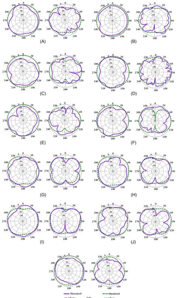
FIGURE 4 Measured (solid line) and simulated (dash line) normalized radiation patterns of the monopole antenna in the xy-plane (left side) and yz-plane (right side) at: A, 1.9 GHz; B, 2.75 GHz; C, 3.7 GHz; D, 4.1 GHz; E, 4.6 GHz; F, 4.8 GHz; G, 8.51 GHz; H, 8.9 GHz; I, 9 GHz; J, 9.7 GHz; and K, 11 GHz [Color figure can be viewed at wileyonlinelibrary.com]
Therefore, in this section, we provided some examples of current distribution and related resonances. Figure 3 shows simulated surface current distribution at various resonance frequencies.
In ALL OFF case, the antenna resonates at two frequen-cies (4.7 GHz and 8.72 GHz). Although the two switches are OFF, still, there is strong surface current at 8.72 GHz at the upper region of the antenna containing the crown-like shape (see Figure 3). The size of this region is comparable to the wavelength at these two frequencies causing strong induced current. However, at 4.7 GHz, the surface current is mainly concentrated at the feed line and the ground plane near it. In addition, there is some current at the outer bound-ary of the antenna.
When S1 is ON and S2 is OFF, the surface current redis-tributes from lower region to upper region via S1 which causes four resonances (2.9 GHz, 4.12 GHz, 9 GHz, and 9.5 GHz). The surface current at 2.9 GHz and 4.12 GHz is mainly concentrated in regions near switch S1, feed line, and ground plane near the feed line. However, the current in the lower region of the antenna is stronger at 2.9 GHz than 4.12 GHz. Moreover, the surface current is stronger at the right side of the antenna at 9 GHz and 9.5 GHz. The electri-cal size of the antenna at these two frequencies is almost half of a wavelength, if we look at region where current is stron-ger. The OFF state of S2 is causing weak current at the left side of the antenna. As a matter of fact, because the current distribution at 9 GHz is covering almost half a wavelength on the antenna, as a consequence, we expect a dipole-like radiation pattern from the antenna at this frequency. It will be demonstrated in the following section where radiation patterns of the antenna are discussed that at this frequency, the antenna provides donut-like radiation pattern.
When S2 is ON and S1 is OFF, the surface current redis-tributes from lower region to upper region via S2 which causes three resonances (1.8 GHz, 4.58 GHz, and 8.51 GHz). At these frequencies, the current is mainly concentrated at the left side of the antenna except at 8.51 GHz, which also has strong current at right side of the antenna. Furthermore, the lowest resonance frequency can be estimated from the longest
effective surface current path (Leff=λeff/2).22 Of note, 1.8 GHz is the lowest frequency of the antenna in simula-tion, and the Leff is approximated using the method described in Reference 22. Figure 3 shows the current path for Leff = 52 mm. The lowest frequency (f = c/λeff,λeff = 2 Leff
ffiffiffiffiffiffiffiffiffiffiffiffiffiffiffiffiffiffiffiffi εr+ 1
ð Þ=2
p
is 1.94 GHz.22The measured results show that the lowest resonant frequency is 1.9 GHz which is quite close to the calculated value. The reason for small difference in measurement and simulated lowest frequency can be due to simulation inaccuracy.
Finally, when both switches are in the ON state, a new resonance appears at 3.68 GHz. The surface current is mainly concentrated on the feed line and ground near it.
2.3
| Radiation patterns on the antenna
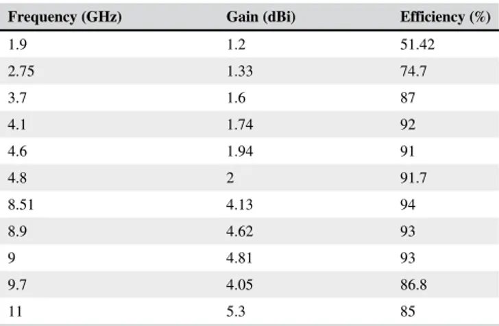
To determine the radiation characteristic of the antenna, we measured the radiation patterns of the antenna in anechoic chamber in xy and yz plane. Figure 4 shows the simulated and measured normalized radiation patterns of the antenna at different resonance frequencies in xy and yz plane. There is a good agreement between simulated and measured patterns of the antenna. The experimental results are proof of an omni-directional behavior from monopole antenna except at cer-tain frequencies where this behavior is slightly distorted. The reason for that is the marginal distribution of the surface current on the antenna. Although the antenna has asymmet-ric geometry, the radiation patterns are almost symmetasymmet-ric. The omni-directional behavior of the antenna shows that it could be an ideal candidate for various wireless applications. The simulated gain and total radiation efficiency of the antenna are tabulated in Table 1 at several resonance frequen-cies. The antenna gain is varying from 1.2 to 5.3 dBi. How-ever, the radiation efficiency is varying from 70% to 94% except at 1.9 GHz where efficiency drops to 51.42%. The small efficiency at 1.9 GHz is due to the small electrical size of the antenna at this frequency. At high frequency, the elec-trical size of the antenna is large enough to give high gain and efficiency. These crucial results together with the frequency reconfigurability of the compact monopole antenna allow it to be used for cognitive radio and handheld portable devices.
3
| C O N C L U S I O N S
This letter presents a novel design of optically reconfigur-able antenna for cognitive radio application. The multi-band reconfigurable antenna is designed by using HR Si pieces acting as optically tunable resistors. This concept is demonstrated in terms of experimental reflection coeffi-cient and radiation patterns of the antenna. The frequency reconfigurability of the antenna is visible from the return loss plots. The omni-directional radiation behavior of the antenna shows that the antenna is suited for various wire-less applications.
TABLE 1 Simulated gain and radiation efficiency of the antenna Frequency (GHz) Gain (dBi) Efficiency (%)
1.9 1.2 51.42 2.75 1.33 74.7 3.7 1.6 87 4.1 1.74 92 4.6 1.94 91 4.8 2 91.7 8.51 4.13 94 8.9 4.62 93 9 4.81 93 9.7 4.05 86.8 11 5.3 85
In future, various optically reconfigurable antennas can be designed for 5G or next generation wireless networks. This method can be applied to design multiband polarization and pattern agile antennas.
A C K N O W L E D G M E N T
The authors thank the H2020 ITN CELTA under grant num-ber 675683 of Call: H2020-MSCA-ITN-2015.
O R C I D
Abdul Ali https://orcid.org/0000-0002-0095-6702
Muhammad Alibakhshikenari https://orcid.org/0000-0001-6074-8019
R E F E R E N C E S
[1] Tawk Y, Costantine J, Christodoulou CG. Cognitive-radio and antenna functionalities: a tutorial [wireless corner]. IEEE Anten-nas Propag Mag. 2014;56(1):231-243.
[2] Aboufoul T, Alomainy A, Parini C. Reconfiguring uwb monopole antenna for cognitive radio applications using GaAs fet switches. IEEE Antennas Wirel Propag Lett. 2012;11:392-394.
[3] Ali A, Topalli K, Ramzan M, Khan TM, Altintas A, Colantonio P. Optical characterization of high and low resistive silicon samples suitable for reconfigurable antenna design. Microw Opt Technol Lett. 2019;61:107-110. https://doi.org/10.1002/mop.31506. [4] Majid HA, Kamal M, Rahim A, et al. Reconfigurable notched
wideband antenna using ebg structure. Microw Opt Technol Lett. 2014;57(2):497-501. [Online]. Available: https://onlinelibrary. wiley.com/doi/abs/10.1002/mop.28882.
[5] Nikolaou S, Bairavasubramanian R, Lugo C, et al. Pattern and fre-quency reconfigurable annular slot antenna using pin diodes. IEEE Trans Antennas Propag. 2006;54(2):439-448.
[6] Lai MI, Wu TY, Hsieh JC, Wang CH, Jeng SK. Design of reconfigur-able antennas based on an l-shaped slot and pin diodes for compact wireless devices. IET Microw Antenna Propag. 2009;3(1):47-54. [7] Goncalves R, Pinho P, Carvalho NB. Compact, frequency
reconfi-gurable, printed monopole antenna. Int J Antennas Propag. 2012; 2012:1-6.
[8] Pringle LN, Harms PH, Blalock SP, et al. A reconfigurable aperture antenna based on switched links between electrically small metallic patches. IEEE Trans Antennas Propag. 2004;52(6):1434-1445. [9] Tawk Y, Costantine J, Christodoulou CG. A varactor-based
reconfi-gurable filtenna. IEEE Antennas Wirel Propag Lett. 2012;11:716-719. [10] Tariq A, Ghafouri-Shiraz H. Frequency-reconfigurable monopole
antennas. IEEE Trans Antennas Propag. 2012;60(1):44-50.
[11] Zohur A, Mopidevi H, Rodrigo D, Unlu M, Jofre L, Cetiner BA. Rf mems reconfigurable two-band antenna. IEEE Antennas Wirel Propag Lett. 2013;12:72-75.
[12] Chiu CY, Li J, Song S, Murch RD. Frequency-reconfigurable pixel slot antenna. IEEE Trans Antennas Propag. 2012;60(10): 4921-4924.
[13] Erdil E, Topalli K, Unlu M, Civi OA, Akin T. Frequency tunable microstrip patch antenna using rf mems technology. IEEE Trans Antennas Propag. 2007;55(4):1193-1196.
[14] Panagamuwa CJ, Chauraya A, Vardaxoglou JC. Frequency and beam reconfigurable antenna using photoconducting switches. IEEE Trans Antennas Propag. 2006;54(2):449-454.
[15] Panagamuwa CJ, Vardaxoglou JC. Optically reconfigurable bal-anced dipole antenna. Paper presented at: Twelfth International Conference on Antennas and Propagation, 2003 (ICAP 2003). (Conf. Publ. No. 491); vol. 1; March 2003; pp. 237–240. [16] Silva LG, Alves AAC, Sodr AC. Optically controlled
reconfigur-able filtenna. Int J Antennas Propag. 2016;2016:1-9.
[17] Collett MA, Gamlath CD, Cryan MJ. Optically induced conductiv-ity in silicon: an active control technique for antennas. Microw Opt Technol Lett. 2016;58(4):994-998. [Online]. Available: https://onli-nelibrary.wiley.com/doi/abs/10.1002/mop.29713.
[18] Pendharker S, Shevgaonkar RK, Chandorkar AN. Optically con-trolled frequency-reconfigurable microstrip antenna with low photo-conductivity. IEEE Antennas Wirel Propag Lett. 2014;13:99-102. [19] Tawk Y, Albrecht AR, Hemmady S, Balakrishnan G,
Christodoulou CG. Optically pumped frequency reconfigurable antenna design. IEEE Antennas Wirel Propag Lett. 2010;9:280-283. [20] Tawk Y, Costantine J, Hemmady S, Balakrishnan G, Avery K,
Christodoulou CG. Demonstration of a cognitive radio front end using an optically pumped reconfigurable antenna system (opras). IEEE Trans Antennas Propag. 2012;60(2):1075-1083.
[21] Callister WD, Rethwisch DG. Materials Science and Engineer-ing: An Introduction. 9th ed. Wiley: New York; 2013.
[22] Chen ZN, See TSP, Qing X. Small printed ultrawideband antenna with reduced ground plane effect. IEEE Trans Antennas Propag. 2007;55(2):383-388.
How to cite this article: Ali A, Topalli K,
Ramzan M, et al. Optically reconfigurable planar monopole antenna for cognitive radio application.
Microw Opt Technol Lett. 2019;61:1110–1115.
![FIGURE 2 Measurement and simulation results for the reflection coefficient of the antenna for different switch positions [Color figure can be viewed at wileyonlinelibrary.com]](https://thumb-eu.123doks.com/thumbv2/9libnet/5928632.123228/3.892.84.552.381.1074/figure-measurement-simulation-reflection-coefficient-different-positions-wileyonlinelibrary.webp)