ESTABLISHMENT OF AN FPGA-BASED REAL-TIME IM EXPERIMENTAL SETUP AND ONLINE IM MODEL VERIFICATION
Remzi INAN1,+, Murat BARUT1
1Niğde Ömer Halisdemir University, Faculty of Engineering, Department of Electrical and Electronics Engineering, Niğde Turkey
[email protected] [email protected]
Abstract
In this study, Serial Peripheral Interface (SPI) communication between the ADS 8568 EVM-PDK (Evolution Performance Development Kit) Analog to Digital Converter (ADC) developed by Texas Instrument and Xilinx XC5VLX110T FPGA board is implemented in order to verify Induction Motor (IM) model in real-time. Analog datas obtained from the voltage, current and torque transducers are converted to digital datas by ADC and read with FPGA simultaneously in real-time. Thus, the αβ- stator stationary axis components of the stator voltage ( and ) and αβ- axis components of the stator current ( and ) are calculated by Clarke transformation. The load torque is obtained by passing the measured signals from the torque transducer through the low-pass filter which is implemented on the FPGA using 64-bit double floating number format. In addition, the signals obtained from the incremental encoder are read by the FPGA after the voltage level shifting with 74LS245P Integrated Circuit (IC), so that mechanical speed (or ) of the rotor can be measured. All measurement algorithms except for the lowpass filter constructed for load torque measurement are implemented with VHDL by using 32-bit single floating numbers. The real-time verification of the rotor flux-based IM model is performed offline before it is implemented on FPGA by using the stator voltages, currents and load torque measured from the IM by using the simultaneous measurement unit in real-time. Thus, an FPGA-based real-time open-loop experimental setup of IM is established for the future works about the estimator/observer based speed-sensorless control of IMs.
Keywords: FPGA, induction motor, parallel programming, estimated-based
speed-sensorless control, VHDL.
+ This paper has been presented at the ICENTE'17 (International Conference on Engineering Technologies)
1. Introduction
In the process of developing engineering designs, the verification and testing of motor controllers used for electric vehicles is a time consuming operation with high cost. Also, testing the high-power controllers can lead to safety problems [1]. As it is well-known, modelling is a mathematical expression of a physical system in all areas and simulation is a hardware or software calculation based platform where these models can be tested numerically. High accuracy and high speed modeling and analysis equipment are needed for design optimization, dynamic characteristic analysis, controller design, and transient stability analysis of electrical machines [2]. Lately, the performances of the IM control methods proposed in the literature are extensively tested on hardware in the loop (HIL) system which is basis for the real-time simulation platforms [1]. The HIL methodologies that form real-time emulator systems have a widespread acceptance since they provide a fast and safety test environment in the design of automotive, energy and aerospace, especially in the creation of measurement systems, electronic circuit design and industrial control applications [3].
On the other hand, sampling time is important in HIL simulator or in real-time emulators, if not as much as in real-time experimental environments [4]. It is known that a system must be able to be rapidly calculated in a simulation platform so that it can be realized with low sampling time. That is why FPGAs with fast processing capacity are finding applications today in real-time emulator [5]. FPGAs have low I/O latency and the ability to process in nanoseconds makes them suitable for real-time simulation of high frequency signals [2]. FPGAs offer a parallel architectural structure that can fully match the required mathematical and logical expressions of the algorithms to be implemented. The parallel simultaneously processing ability allows FPGAs to reduce sampling time [5].
There are some studies in the literature about the simulation of electrical motor control and driver algorithm with motor model and driver model or verification of the electrical motor model in FPGA-based HIL system or real-time emulator [1, 3-12]. In [3], it is demonstrated that a novel real-time emulator of a permanent magnet synchronous motor (PMSM) drive suitable for HIL testing of both healthy and faulty conditions, considering in particular stator short-circuit. This emulator is implemented on FPGA with 32-bit fixed
point numbers. Ref. [6] presents a test setup for the analytical modelling of a three-phase low voltage IM drive model in closed-loop. The model is developed in MATLAB Simulink by using C language based S-functions compatible with the real-time workshop (RTW) platform which is constructed on FPGA. In [1], a nonlinear approach of a real-time IM model and control system are implemented in a National Instruments real-real-time platform and then, the HIL simulation results are compared with real values of IM states obtained by measurements. In [4], the IM model is verified offline on FPGA in HIL and real rotor speed obtained from the experimental setup is compared with simulation result. However, in this study, any FPGA board is not included to the real-time IM experimental setup. In [7], FPGA is programmed by using real-time interface of Opal-RT-based platforms which utilizes a Xilinx Virtex 6 FPGA in order to model the system; The codes of FPGA are constructed by blocks. An external DSP-based controller is used to generate the signal of the converter model implemented on FPGA with IM model in HIL. The outputs obtained from the models are saved in real-time by using digital to analogue converter (DAC) and ADC connected to terminals of FPGA board for applying the gate signals obtained from DSP to the converter model. So the HIL control performance of the electrical vehicle system is tested. In [8], voltage source inverter (VSI) model, PWM technique, and IM model are implemented on FPGA with VHDL. Also, DSP–based IM experimental setup is operated under the same conditions and real-time results are compared with the simulation results obtained from the FPGA-based HIL system. Ref. [9] introduces an FPGA-based implementation of offline HIL emulator of nonlinear dynamic model of IM; A digital three-phase power source generates the required line to line voltages for emulating the manner of an ADC. In [5], a real-time HIL emulator of a synchronous motor (SM) includes SM delta-operator model, VSI model, and model of a mechanical load. However, the emulator is run on ModelSim which is the software-based simulator of the FPGA; Thus, it is not possible to say that the proposed system is tested on a hardware platform. Also Refs. [10] and [11] demonstrate offline HIL verification of the IM model on FPGA. In [12], the actual stator voltages and load torque are measured from DSP-based open-loop IM experimental setup and registered to memories of the FPGA. Then actual voltages and load torque are applied to the IM model which is implemented on FPGA. Thus, the IM model is verified offline in HIL system.
There is no clear statement in the literature about how a real-time HIL system is established in an IM experimental setup. Also it is seen from the literature that some studies are implemented offline on HIL system, but the authors affirm that the studies are about the real-time emulator of IM or a control method of IM. In addition, the results are given in a short time interval in the existing literature.
The HIL systems are classified as two types: The first type of HIL system is called as controller HIL (CHIL). In CHIL system, there is no power transfer to or from the hardware-based controller and the power system is implemented on controller as a virtual system. The other type of HIL is named as power HIL (PHIL). The PHIL system involves power transfer to or from the hardware under test [13]. Thus, in this study, a PHIL system is implemented on an FPGA-based real-time IM experimental setup to verify the rotor flux-based IM model by using the measured actual values of stator voltages and load torque of the IM and the established experimental setup is introduced in detail. The IM model and SPI communication which is used for the data transfer between the FPGA and ADC board are implemented with VHDL on FPGA. The measured real values of the states (stator voltages, stator currents, load torque and rotor speed) and results of the IM model are sent to PC via Ethernet communication which constructed on FPGA with Ethernet Wrapper core of the FPGA. Then the row Ethernet packages are grabbed by Wireshark and converted to meaningful values by PERL software language. The meaningful values about the measured states and simulation results obtained from the IM model are graphically evaluated on MATLAB.
This paper is organized as follows: After the introduction in Section I; the FPGA-based real-time IM experimental setup are defined in Section II. Implementation of the SPI communication between ADC and FPGA is given in Section III while Section IV describes the discretized rotor flux-based IM model and real-time verification results. The comparison of offline and online FPGA-based IM experimental setup is given in Section V. Finally, conclusions and the suggestions for the future studies are explained in Section VI.
2. FPGA-Based Real-Time IM Experimental Setup
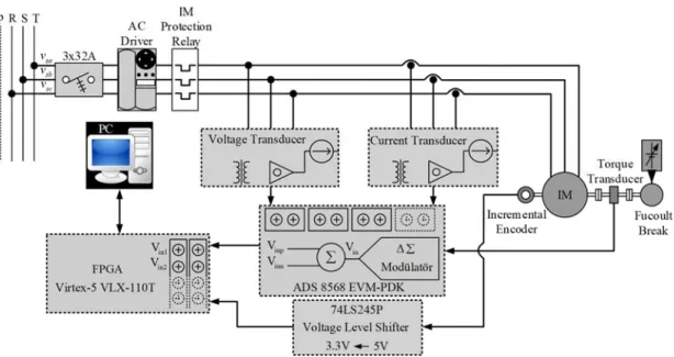
The FPGA-based open-loop IM experimental setup established with the aim of real-time online verification of the IM model is shown in Fig. 1. The components used in the
experimental setup which is shown in Fig. 1 are given as follows:
ADS 8568 EVM-PDK ADC is manufactured by Texas Instruments.
DRBK-50 series torque transducer is produced by ETH and has 50 [N.m] torque capacity to load IM.
ERN120 series 5000 lines incremental encoder is utilized to measure the rotor mechanical speed of the IM and 74LS245P integrated circuit (IC) is used for voltage level shifting between the encoder output signal and FPGA digital I/O ports. LV100-400 voltage transducers and LA55-P/SP1 current transducers manufactured by LEM is utilized to measure three-phase voltages and currents of IM, respectively.
Xilinx Virtex 5 XC5VLX110T FPGA is used for constructing the VHDL commands of IM model and evaluation commands of ADC module by using the parallel architecture of FPGA inherently.
2.2 [kW] IM is manufactured by TEE Electric Motors.
Figure l. Schematic representation of FPGA-based real-time IM experimental setup The ADS 8568 EVM-PDK ADC which is capable of 16-bit dual-polarity measurement is used between sensors and FPGA in order to evaluate the information obtained from the voltage, current and torque transducers in the FPGA-based real-time IM experimental setup. In addition, the 74LS245P voltage level shifter IC reducing 5 [V] to 3.3 [V] is convert the voltage level of the incremental encoder terminals to the appropriate voltage levels of the FPGA terminals. In order to determine the exact value of the load-torque
obtained from the moment transducer, the fourth-order low-pass filter is implemented in the FPGA. The coefficients of the low-pass filter implemented on the FPGA are determined by MATLAB. The discrete-time mathematical expressions of the low-pass filter are implemented using 64-bit floating point numbers to improve the accuracy of the low-pass filter.
3. FPGA-Based Real-Time IM Experimental Setup
The ADS 8568 EVM-PDK ADC which is used to obtain real values of the three phase stator voltages, stator currents and load torque of IM from the voltage, current, and torque transducers have the following electrical features:
16-bit resolution.
8 simultanous bipolar analog input channels. 400 Ksps sampling rate.
Data transfromation by SPI or Frame Synchronous (FSYN) parallel communication.
∓10 and ∓5 selectable analog input voltage range. 3.3 and 5 selectable digital output voltage level.
In case of using only EVM layer of ADS8568 EVM-PDK ADC, it is suggested that the converter data should be transferred by SPI protocol [14-15]. The SPI communication between ADC and FPGA is performed by using the timing diagram which is shown in Fig. 2. This timing diagram is offered in [14] and all time requirements are arranged in FPGA by using a state machine loop implemented with VHDL.
The meanings and functions of the signals given in Fig. 2 are described as follows: XCLK indicates the internal clock frequency of ADS 8568 EVM-PDK ADC. CONVST_x is sent to ADC from an external microcontroller and indicates that the ADC starts analogue to digital conversion.
BUSY is an output digital signal of the ADC and shows that whether the conversion has finished.
(FS) is an output digital signal of the ADC and describes that digital data can be read from ADC.
microcontroller.
SDO_x illustrates the digital outputs of ADC (There are four digital output channels in ADC and every output channel carries 32-bit data string which is formed by putting in order two 16-bit output channels in one string)
Figure 2. Timing diagram of SPI protocol [14]
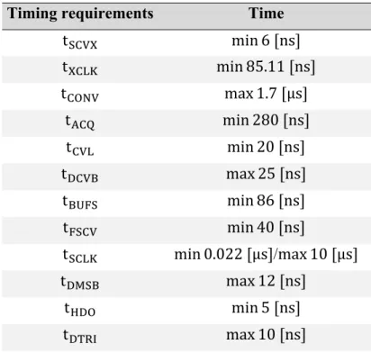
Table 1. Timing requirements for implementing the SPI communication on FPGA
Timing requirements Time
t min 6 ns t min 85.11 ns t max 1.7 μs t min 280 ns t min 20 ns t max 25 ns t min 86 ns t min 40 ns t min 0.022 μs /max 10 μs t max 12 ns t min 5 ns t max 10 ns
Furthermore, the timings mentioned in Fig. 2 are given in Table 1. The SPI communication between ADC and FPGA is implemented on FPGA with VHDL by
XCLK CONVST_x BUSY FS SCLK SDO_x SCVX t tXCLK tCVL CONV t tACQ DCVB t BUFS t FSCV t HDO t DMSB t SCLK t DTRI t CH_x0 MSB CH_x1D3 CH_x1D2 CH_x1D1 CH_x1LSB
regarding the time requirements given in Table 1. Thus the three-phase stator voltages, stator currents and load torque can be measured in real-time by FPGA.
The digital 16-bit binary data obtained from the ADC are converted to decimal values in FPGA with VHDL by using 32-bit single floating point number multiplier and divider. The quantization function given in (1) is used to obtain the decimal values of the measured quantities from the 16-bit binary values.
(1)
The voltage levels of outputs of the voltage, current and torque transducers are ∓5 . However, the voltage levels of analogue input channels of the ADC are setted to ∓10 to prevent damage caused by voltage fluctuations that can occur at the outputs of the transducers.
4. Discretized Rotor Flux-Based IM Model and Real-Time Verification Results
In order to verify the IM model in real-time, the rotor flux based IM model is used in this study. The discretized IM model fixed with the αβ-stator stationary reference frame is given as below:
1 ,
(2)
(Measurement Equation)
(3)
The matrices given in (2) and (3) are described as follows: 0 0 0 0 0 0 0 0 0 0 0 0 0 0 0 0 0 0 , 0 0 0 0 , 1 0 0 0 0 0 1 0 0 0 ,
1 , , , , 1 ,
, , 1 , ,
Here, is extended state space vector. is nonlinear function of states and inputs. ,is system matrice. is control input vector. is input matrice. is system noise. is load torque effect matrice. is function of outputs. is measurement matrice. is measurement noise. is pole pair. and are stator and rotor resistance, respectively. is stator transient inductance. 1 , leakage or coupling factor. and are stator and rotor inductance, respectively. and are stator and rotor leakage inductance, respectively. is magnetizing inductance. and are total inertia and viscous friction, respectively. is sampling time.
The rated parameters of the IM used in the real-time verification of IM model are given in Table 2, the same motor parameters are also used in [16].
Table 2. IM parameters used for the verification of IM model
P [kW] f [Hz] JT[kg.m2] [Nm/(rad/sn)] Pp 2.2 50 0.055 0.0019 3 V [V] I[A] Rs[Ω] Rr’[Ω] Ls[H] 380 5.5 3.03 2.53 0.1466 Lr’[H] Lm[H] nm[rpm] tL[N.m] 0.1524 0.135 1000 20
Figure 3. The real values of (a) and variations, (b) and variations measured from FPGA-based IM experimental setup
&[ ] ss vv V 4.36 4.43 -300 0 300 t[s] (a) &[ ] ss ii A -10 0 10 4.36 4.43 t[s] (b)
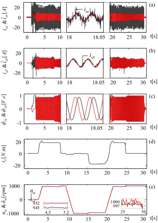
Figure 4. The actual values of the IM states measured from the real-time experimental setup and the results obtained from FPGA-based IM model; (a) vs. ̂ variations,
(b) vs. ̂ variations, (c) vs. variations, (d) variations,(e) vs. variations
The real values of , , , and measured from FPGA-based IM experimental setup are shown in Fig. 3. The results of the real-time verification of the IM model on the FPGA are given in Fig. 4. As shown in Fig. 4, IM is accelerated from zero
ˆ &[ ] ss ii A -20 0 10 0 20 20 30 18 18.05 25 t[s] 5 s i (a) ˆ &[ ] ss ii A -20 0 20 0 5 10 18 18.05 20 25 30 t[s] s i (b) -1 0 1 0 5 10 18 18.05 20 25 30 t[s] (c) ˆˆ &[ . ] rr Vs [. m ] L tN 0 5 10 15 20 25 -20 0 20 30 t[s] (d) ˆ &[ ] mm nn rp m -1000 0 1000 0 5 10 15 20 25 30 t[s] 4.5 5.5 945 952 25 30 997 1000 m n (e)
speed to half of the rated speed under 19 load torque and is operated at 952 in the range of 3 8 . The load torque is increased to 5 . , 10 . , and 20 . at 9.5. , 9.5. , and 9.5. respectively and IM is operated at half of the rated rotor speed ( 1000 ) for about 1.5 under various load torque conditions. The direction of rotation of IM is reversed at 9.5. and operated at half rated speed ( 1000 ) in reverse direction between at 11.5
15.5 time interval. The load torque is increased to 18.5 at 15.5. and the rotor mechanical speed is decreased to 953 by operating the IM via an ac driver in open-loop without speed feedback. Then direction of IM is reversed and accelerated to its rated speed. The IM is operated at 952 / in forward direction in the range of 21.5 25 under 18.5 load torque. After that, the load torque is decreased to zero and IM is operated at rated speed 1000
until the end of the test scenario.
It is shown that, under all speed and load torque variations, the speed and current information obtained from the IM model implemented on the FPGA overlaps with their actual values obtained from the real-time experimental setup. Thus, the accuracy of the FPGA-based IM emulator is experimentally verified.
Table 3. The computation times of the algorithms implemented on the FPGA for the real-time verification of the IM model
Algorithm Time (µs) IM Model 0.69 ADC (SPI) 3.28
Total 3.97
T (Sampling Time) 15
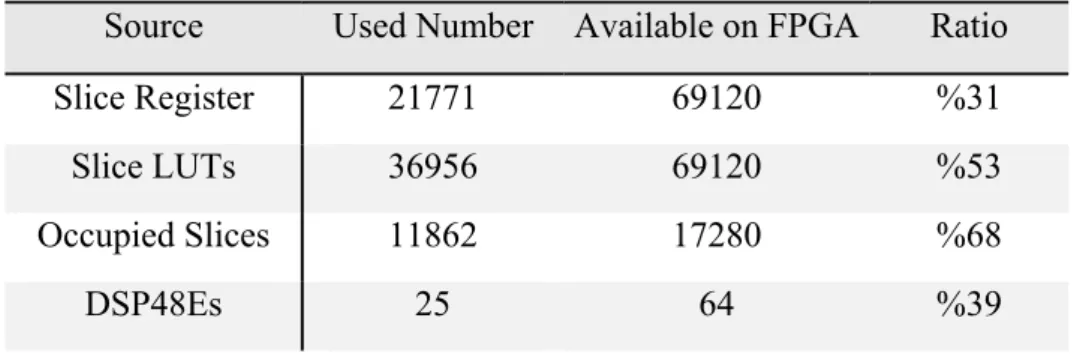
Table 4. The numbers and ratios of the logical units used for the implementation of FPGA-based real-time emulator of the IM.
Source Used Number Available on FPGA Ratio
Slice Register 21771 69120 %31
Slice LUTs 36956 69120 %53
Occupied Slices 11862 17280 %68
The duration of data read from the ADC with SPI communication and the implementation time of IM model on FPGA are given in Table 3. The sampling time of the HIL system is defined as 15 , despite the overall system can be implemented in 3.97 , in order to prevent the data loss while the Ethernet communication is provided between the FPGA and PC. Also, the numbers and ratios of the logical units used on the FPGA are given in Table 4.
5. Comparison of Offline and Online FPGA-Based IM Experimental Setup
Fig. 5 shows the experimental setup and FPGA flow chart of the offline verification of IM model which is proposed firstly in [12].
Figure 5. Offline verification of IM model on FPGA HIL system [12]
In this study, fully FPGA-based experimental IM model setup is used for online real-time verification of the IM model which offline verification is implemented in [12]. In [12], firstly the measured αβ- components of stator voltage and load torque are saved to RAM blocks of FPGA. Then the measured states of IM are applied to IM model in HIL system and thus the offline verification of the IM model is accomplished in HIL system. In offline HIL system, sampling time of the algorithm is specified as 50 because the measured αβ- components of stator voltage and load torque are obtained by DSP-based experimental setup in 50 sampling time. In online real-time experimental setup the sampling time is reduced to 3.97 but for the data transfer with the Ethernet protocol, this value is taken as 15 . As a result, a fully FPGA-based IM experimental setup is implemented with ADC and thus the sampling time is reduced dramatically by fast ADC operation and SPI communication between FPGA and ADC board. Furthermore, the real-time application of control and estimator algorithm for speed-sensorless control of IM can be implemented rapidly and performances of these algorithm can be improved by the reduction of the sampling time. The comparison of the sampling time of two different platform-based experimental setup is given in Table 5.
Table 5. Sampling time comparison of offline and online verification of IM model Experimental IM Setup Sampling Time ( )
DSP/FPGA-Based Experimental Setup
(Offline Real-Time Verification) 50 Fully FPGA-Based Experimental Setup
(Online Real-Time Verification)
3.97 (Taken as 15 for Ethernet Communication)
6. Conclusion
In this study, the IM rotor flux-based model is verified by using the FPGA-based real-time IM experimental setup and also the detailed description of how the experimental setup is established is presented. Here, the ADC which is used for the data acquisition from the IM is communicated with the FPGA via SPI. Thus, it is demonstrated that the IM control methods and state/parameter observers/estimators can be realized in real-time with low sampling time by using the parallel processing capability of the FPGAs.
Moreover, this study confirms that FPGAs, which have gained importance in today's industry can be a good alternative with lower cost for industrial control applications.
References
[1] J. Shen, G. Xu, Y. Xu, L. Qiu, and G. Li, “National instrument-based experimental validation of a nonlinear real-time induction motor model in an EV simulation system”, 2017 IEEE Int. Conf. on Industrial Technology (ICIT), pp. 959-964.
[2] S. Mojlish, N. Erdogan, D. Levine, and A. Davoudi, ”Review of Hardware Platforms for Real-Time Simulation of Electric Machines”, IEEE Transactions on Transportation Electrification, vol. 3 (1), pp. 130-146, March 2017.
[3] F. Alvarez-Gonzalez, A. Griffo, B. Sen, and J. Wang,”Real-Time Hardware-in-the-Loop Simulation of Permanent-Magnet Synchronous Motor Drives Under Stator Faults”, IEEE Transactions on Industrial Electronics, vol. 64 (9), pp. 6960-6969, September 2017.
[4] N. R. Tavana and V. Dinavahi, “A General Framework for FPGA-Based Real-Time Emulation of Electrical Machines for HIL Applications”, IEEE Transactions on Industrial Electronics, vol. 62 (4), pp. 2041-2053, April 2015.
[5] M. Dagbagi, L. Idkhajine, E. Monmasson, L. Charaabi, I. Slama-Belkhodja, “FPGA implementation of a synchronous motor real-time emulator based on delta operator”, 2011 IEEE Int. Symp. on Industrial Electronics, pp. 1581-1586.
[6] A. Ingalalli and J. V. V. N. Bapiraju, “Analytical model for real time simulation of low voltage induction motor drive”, 2017 IEEE Int. Electric Machines and Drives Conf. (IEMDC), pp. 1-8.
[7] L. Herrera, C. Li, X. Yao, and J. Wang, “FPGA-Based Detailed Real-Time Simulation of Power Converters and Electric Machines for EV HIL Applications”, IEEE Transactions on Industry Application, vol. 51 (2), pp. 1702-1712, March 2015.
[8] R. Gregor, G. Valenzano, J. Rodríguez-Piñeiro, and J. Rodas, “FPGA-based real-time simulation of a Dual Three-Phase Induction Machine”, 2014 16th European Conf. on Power Electronics and Applications, pp. 1-8.
[9] M. A. Esparza, R. Alvarez-Salas, H. Miranda, E. Cabal-Yepez, A. Garcia-Perez, R. J. Romero-Troncoso, and R. A. Osornio-Rios, “Real-time emulator of an induction
motor: FPGA-based implementation”, 2012 9th Int. Conf. on Electrical Engineering, Computing Science and Automatic Control (CCE), pp. 1-6.
[10] M. Dagbagi, L. Charaabi, L. Idkhajine, E. Monmasson, and I. Slama-Belkhodja, “Digital implementation using delta operator for FPGA-based induction motor emulator”, Eighth Int. Multi-Conf. on Systems, Signals Devices, pp. 1-6.
[11] L. Charaabi, E. Monmasson, and I. Slama-Belkhodja, “FPGA-based real-time emulation of induction motor using fixed point representation”, 2008 34th Annual Conf. of IEEE Industrial Electronics, pp. 2393-2398.
[12] R. Inan, M. Barut, and F. Karakaya, "Asenkron motor modeli kullanılarak MATLAB yazılımı ile FPGA donanım ortamındaki hesaplamaların karşılaştırılması", 2012 Otomatik Kontrol Türk Milli Komitesi Otomatik Kontrol Ulusal Toplantısı-TOK 2012, pp. 835-839.
[13] X. Guillaud, M. O. Faruque, A. Teninge, A. H. Hariri, L. Vanfretti, M. Paolone, V. Dinavahi, P. Mitra, G. Lauss, C. Dufour, P. Forsyth, A. K. Srivastava, K. Strunz, T. Strasser, and A. Davoudi, ”Applications of Real-Time Simulation Technologies in Power and Energy Systems”, IEEE Power and Energy Technology Systems Journal, vol. 2 (3), pp. 103-115, September 2015.
[14] ADS 8528, 8548, 8568 Data Manual, Texas Instruments, 2016. [15] ADS 8568 EVM-PDK User Manual, Texas Instruments, 2016.
[16] M. Barut, R. Demir, E. Zerdali, and R. Inan, "Real-time implementation of bi input-extended Kalman filter-based estimator for speed-sensorless control of induction motors", IEEE Trans. on Industrial Electronics, vol. 59 (11), pp. 4197-4206, November 2012.
![Table 2. IM parameters used for the verification of IM model P [kW] f [Hz] J T [kg.m 2 ] [Nm/(rad/sn)] P p 2.2 50 0.055 0.0019 3 V [V] I[A] R s [Ω] R r ’ [Ω] L s [H] 380 5.5 3.03 2.53 0.1466 L r ’ [H] L m [H] n m [rpm] t L [N.m] 0.](https://thumb-eu.123doks.com/thumbv2/9libnet/4846083.94561/9.892.173.713.585.1063/table-im-parameters-used-verification-model-rad-ω.webp)