IFAC-PapersOnLine 49-9 (2016) 117–123
ScienceDirect
ScienceDirect
2405-8963 © 2016, IFAC (International Federation of Automatic Control) Hosting by Elsevier Ltd. All rights reserved. Peer review under responsibility of International Federation of Automatic Control.
© 2016, IFAC (International Federation of Automatic Control) Hosting by Elsevier Ltd. All rights reserved.
Control Loss Recovery Autopilot Design for Fixed-Wing Aircraft
Şeyma Akyürek*, Burak Kürkçü*, Ünver Kaynak *, Coşku Kasnakoğlu*
* TOBB University of Economics and Technology, Ankara, Turkey 06560. (e-mail:{seymaakyurek, kurkcub, unkaynak, kasnakoglu}@gmail.com) Abstract:
In this paper a loop-shaping design approach is investigated for distressed fixed-wing aircraft experiencing control loss due to surface or power failure. An accurate nonlinear model of the aircraft dynamics is utilized to obtain a target aircraft behavior in the emergency situation, for which a loop-shaping controller is designed to balance performance and robustness, and to decouple different command channels. A rudder servoactuator jam scenario is presented as an example where it is seen that the autopilot recovers level flight and responds well to fly-by-wire commands from the operator.
Keywords: Loop-shaping, loss of control, surface jam, power loss, autopilot design, numerical simulation.
1. INTRODUCTION
Many aviation accidents have been caused by the sudden or gradual loss of control of the aircraft (Belcastro & Foster, 2010). Such loss of control may be caused by mechanical failures, human factors or environmental conditions. The first one includes control surface and engine failures and will physically limit the power and flight envelope of the aircraft, perhaps causing it to fly in unusual attitudes. The second and third factors are also important since pilot error and atmospheric conditions have been determined to be responsible for many accidents in aviation history (Gero, 2013).
Significant research effort has been devoted in literature to classifying aircraft loss of control accidents, as well as intervention mechanisms for preventing or recovering from mechanical failure, human errors and environmental factors (Belcastro, et al., 2014). Many of the recovery type approaches targeted are white-box methods in the sense that the designer looks at the aircraft dynamics, proposes a specific solution for a specific problem, and comes up with a specific intervention strategy (Yu & Jiang, 2012). This approaches poses some problems and sources of error however, since classical approaches to aircraft modelling and controller design make many assumptions and simplification to achieve decoupling of longitudinal and lateral channels, as well as linear approximations of the dynamics. (Etkin & Reid, 1996), (Nelson, 1998), (Stevens & Lewis, 2003), (Blakelock, 1991). In an emergency control loss situation however, the aircraft will most probably exhibit a highly coupled dynamics and designs based on classical assumptions may not be optimal or even valid (Gill, et al., 2015). The situation deteriorates quite rapidly, perhaps within seconds in such control loss scenarios so if it is desired that the aircraft return to its near uncoupled and linear behavior, the burden must be shifted to an automated control system. This requires the controller to handle the system as a whole, and not separately in the longitudinal and lateral direction. This calls for a multi-input
multi-output design, preferably with good robustness properties.
While multi-input multi-output robust flight controller designs are not uncommon for missile (Choi, et al., 2012), helicopter (Yang & Liu, 2003) and multirotor systems (Liu, Li, Kim, & Zhong, 2014) , they are found in fewer numbers for fixed wing aircraft since it is much practical to design individual controllers for separate channels (Nelson, 1998), (Blakelock, 1991). Unfortunately a loss of control scenario will likely render the standard approaches to separate the channels invalid since the aircraft may end up being in an unusual attitude with one or more of its four user inputs (throttle, aileron, elevator, rudder) being unavailable for recovering the aircraft.
In this paper we design a multi-input multi-output robust controller for a distressed aircraft experiencing some common loss of control scenarios. Alternative to a white-box approach requiring deep analysis of the aircraft dynamics for each such scenario, we take a black-box approach focusing only on input-output effects. This makes the control design methodology similar to each case, despite the physical meaning of the scenarios and their implication on the flight dynamics may be substantially different. The prosed controllers are verified using numerical simulations, hardware-in-the-loop tests, as well as actual flight tests with unmanned aerial vehicles.
2. MATHEMATICAL MODEL OF THE AIRCRAFT The non-linear model of the aircraft dynamics is derived from basic Newtonian mechanics. For a rigid body, the total force and moment equations are:
𝐅 = 𝑚 �𝜕𝐕
𝜕𝑡 + 𝛀 × 𝐕� (1)
𝐌 =𝜕(𝐈 ⋅ 𝛀)𝜕𝑡 + 𝛀 × (𝐈 ⋅ 𝛀) (2)
Control Loss Recovery Autopilot Design for Fixed-Wing Aircraft
Şeyma Akyürek*, Burak Kürkçü*, Ünver Kaynak *, Coşku Kasnakoğlu*
* TOBB University of Economics and Technology, Ankara, Turkey 06560. (e-mail:{seymaakyurek, kurkcub, unkaynak, kasnakoglu}@gmail.com) Abstract:
In this paper a loop-shaping design approach is investigated for distressed fixed-wing aircraft experiencing control loss due to surface or power failure. An accurate nonlinear model of the aircraft dynamics is utilized to obtain a target aircraft behavior in the emergency situation, for which a loop-shaping controller is designed to balance performance and robustness, and to decouple different command channels. A rudder servoactuator jam scenario is presented as an example where it is seen that the autopilot recovers level flight and responds well to fly-by-wire commands from the operator.
Keywords: Loop-shaping, loss of control, surface jam, power loss, autopilot design, numerical simulation.
1. INTRODUCTION
Many aviation accidents have been caused by the sudden or gradual loss of control of the aircraft (Belcastro & Foster, 2010). Such loss of control may be caused by mechanical failures, human factors or environmental conditions. The first one includes control surface and engine failures and will physically limit the power and flight envelope of the aircraft, perhaps causing it to fly in unusual attitudes. The second and third factors are also important since pilot error and atmospheric conditions have been determined to be responsible for many accidents in aviation history (Gero, 2013).
Significant research effort has been devoted in literature to classifying aircraft loss of control accidents, as well as intervention mechanisms for preventing or recovering from mechanical failure, human errors and environmental factors (Belcastro, et al., 2014). Many of the recovery type approaches targeted are white-box methods in the sense that the designer looks at the aircraft dynamics, proposes a specific solution for a specific problem, and comes up with a specific intervention strategy (Yu & Jiang, 2012). This approaches poses some problems and sources of error however, since classical approaches to aircraft modelling and controller design make many assumptions and simplification to achieve decoupling of longitudinal and lateral channels, as well as linear approximations of the dynamics. (Etkin & Reid, 1996), (Nelson, 1998), (Stevens & Lewis, 2003), (Blakelock, 1991). In an emergency control loss situation however, the aircraft will most probably exhibit a highly coupled dynamics and designs based on classical assumptions may not be optimal or even valid (Gill, et al., 2015). The situation deteriorates quite rapidly, perhaps within seconds in such control loss scenarios so if it is desired that the aircraft return to its near uncoupled and linear behavior, the burden must be shifted to an automated control system. This requires the controller to handle the system as a whole, and not separately in the longitudinal and lateral direction. This calls for a multi-input
multi-output design, preferably with good robustness properties.
While multi-input multi-output robust flight controller designs are not uncommon for missile (Choi, et al., 2012), helicopter (Yang & Liu, 2003) and multirotor systems (Liu, Li, Kim, & Zhong, 2014) , they are found in fewer numbers for fixed wing aircraft since it is much practical to design individual controllers for separate channels (Nelson, 1998), (Blakelock, 1991). Unfortunately a loss of control scenario will likely render the standard approaches to separate the channels invalid since the aircraft may end up being in an unusual attitude with one or more of its four user inputs (throttle, aileron, elevator, rudder) being unavailable for recovering the aircraft.
In this paper we design a multi-input multi-output robust controller for a distressed aircraft experiencing some common loss of control scenarios. Alternative to a white-box approach requiring deep analysis of the aircraft dynamics for each such scenario, we take a black-box approach focusing only on input-output effects. This makes the control design methodology similar to each case, despite the physical meaning of the scenarios and their implication on the flight dynamics may be substantially different. The prosed controllers are verified using numerical simulations, hardware-in-the-loop tests, as well as actual flight tests with unmanned aerial vehicles.
2. MATHEMATICAL MODEL OF THE AIRCRAFT The non-linear model of the aircraft dynamics is derived from basic Newtonian mechanics. For a rigid body, the total force and moment equations are:
𝐅 = 𝑚 �𝜕𝐕𝜕𝑡 + 𝛀 × 𝐕� (1)
𝐌 =𝜕(𝐈 ⋅ 𝛀)𝜕𝑡 + 𝛀 × (𝐈 ⋅ 𝛀) (2)
Copyright © 2016 IFAC 117
Control Loss Recovery Autopilot Design for Fixed-Wing Aircraft
Şeyma Akyürek*, Burak Kürkçü*, Ünver Kaynak *, Coşku Kasnakoğlu*
* TOBB University of Economics and Technology, Ankara, Turkey 06560. (e-mail:{seymaakyurek, kurkcub, unkaynak, kasnakoglu}@gmail.com) Abstract:
In this paper a loop-shaping design approach is investigated for distressed fixed-wing aircraft experiencing control loss due to surface or power failure. An accurate nonlinear model of the aircraft dynamics is utilized to obtain a target aircraft behavior in the emergency situation, for which a loop-shaping controller is designed to balance performance and robustness, and to decouple different command channels. A rudder servoactuator jam scenario is presented as an example where it is seen that the autopilot recovers level flight and responds well to fly-by-wire commands from the operator.
Keywords: Loop-shaping, loss of control, surface jam, power loss, autopilot design, numerical simulation.
1. INTRODUCTION
Many aviation accidents have been caused by the sudden or gradual loss of control of the aircraft (Belcastro & Foster, 2010). Such loss of control may be caused by mechanical failures, human factors or environmental conditions. The first one includes control surface and engine failures and will physically limit the power and flight envelope of the aircraft, perhaps causing it to fly in unusual attitudes. The second and third factors are also important since pilot error and atmospheric conditions have been determined to be responsible for many accidents in aviation history (Gero, 2013).
Significant research effort has been devoted in literature to classifying aircraft loss of control accidents, as well as intervention mechanisms for preventing or recovering from mechanical failure, human errors and environmental factors (Belcastro, et al., 2014). Many of the recovery type approaches targeted are white-box methods in the sense that the designer looks at the aircraft dynamics, proposes a specific solution for a specific problem, and comes up with a specific intervention strategy (Yu & Jiang, 2012). This approaches poses some problems and sources of error however, since classical approaches to aircraft modelling and controller design make many assumptions and simplification to achieve decoupling of longitudinal and lateral channels, as well as linear approximations of the dynamics. (Etkin & Reid, 1996), (Nelson, 1998), (Stevens & Lewis, 2003), (Blakelock, 1991). In an emergency control loss situation however, the aircraft will most probably exhibit a highly coupled dynamics and designs based on classical assumptions may not be optimal or even valid (Gill, et al., 2015). The situation deteriorates quite rapidly, perhaps within seconds in such control loss scenarios so if it is desired that the aircraft return to its near uncoupled and linear behavior, the burden must be shifted to an automated control system. This requires the controller to handle the system as a whole, and not separately in the longitudinal and lateral direction. This calls for a multi-input
multi-output design, preferably with good robustness properties.
While multi-input multi-output robust flight controller designs are not uncommon for missile (Choi, et al., 2012), helicopter (Yang & Liu, 2003) and multirotor systems (Liu, Li, Kim, & Zhong, 2014) , they are found in fewer numbers for fixed wing aircraft since it is much practical to design individual controllers for separate channels (Nelson, 1998), (Blakelock, 1991). Unfortunately a loss of control scenario will likely render the standard approaches to separate the channels invalid since the aircraft may end up being in an unusual attitude with one or more of its four user inputs (throttle, aileron, elevator, rudder) being unavailable for recovering the aircraft.
In this paper we design a multi-input multi-output robust controller for a distressed aircraft experiencing some common loss of control scenarios. Alternative to a white-box approach requiring deep analysis of the aircraft dynamics for each such scenario, we take a black-box approach focusing only on input-output effects. This makes the control design methodology similar to each case, despite the physical meaning of the scenarios and their implication on the flight dynamics may be substantially different. The prosed controllers are verified using numerical simulations, hardware-in-the-loop tests, as well as actual flight tests with unmanned aerial vehicles.
2. MATHEMATICAL MODEL OF THE AIRCRAFT The non-linear model of the aircraft dynamics is derived from basic Newtonian mechanics. For a rigid body, the total force and moment equations are:
𝐅 = 𝑚 �𝜕𝐕𝜕𝑡 + 𝛀 × 𝐕� (1)
These equations express the motion of a rigid body relative to an inertial reference frame. 𝐕 = [ 𝑢 𝑣 𝑤 ]� is the velocity
vector at the center of gravity, 𝛀 = [ 𝑝 𝑞 𝑟 ]� is the angular
velocity vector about the center of gravity, 𝐅 = � 𝐹� 𝐹� 𝐹� ��
is the total external force vector, and 𝐌 = [𝐿 𝑀 𝑁 ]� is the
total external moment vector. 𝐈 is the inertia tensor of the rigid body, which is defined as
𝐈 = �
𝐼�� −𝐽�� −𝐽��
−𝐽�� 𝐼�� −𝐽��
−𝐽�� −𝐽�� 𝐼��
� (3)
The coefficients of the matrix 𝐈 are the moments and products of inertia of the rigid body and they are constant for a frame of reference fixed to the aircraft. A manipulation of equations (1)-(2) yields 𝜕𝐕 𝜕𝑡 = 𝐅 𝑚 − 𝛀 × 𝐕 (4) 𝜕(𝐈 ⋅ 𝛀) 𝜕𝑡 = 𝐌 − 𝛀 × (𝐈 ⋅ 𝛀) (5)
from where a state-space model may be derived. The body-axes elements of linear and rotational velocities can be selected as the state variables for the model, whereas the body-axes components of the external forces and moments are the inputs to the model. A problem is that these inputs are in fact reliant upon the state variables so further steps are necessary to couple these back to the forces and moments. Nevertheless, using appropriate manipulations one could arrive at a non-linear state space model as follows:
𝐱̇ = 𝐟 (𝐱, 𝐅(𝑡), 𝐌(𝑡) ) (6)
with:
𝐅 = 𝐠�(𝐱(t), 𝐮(t), 𝐯(t), t) (7)
𝐌 = 𝐠�(𝐱(t), 𝐮(t), 𝐯(t), t) (8)
These equations may be blended into a compact expression
𝐱̇ = 𝐟(𝐱(t), 𝐮(t), 𝐯(t), t) (9)
with state vector 𝐱, input vector 𝐮, disturbance vector 𝐯, and time 𝑡. The state vector 𝐱 ordinarily embodies three linear and three angular velocities from 𝐕 and 𝛀, but it is helpful to add six additional variables characterizing the attitude and location of the aircraft for obtaining a solution of the system. Specifically, the spatial orientation of the aircraft is essential for working out the gravitational force, the altitude is required for the computation of aerodynamic and engine forces both of which are influenced by air density that is a function of the aircraft's altitude. The position of the aircraft with regards to Earth is useful for tasks including evaluating flight trajectories of autopilot designs. In practice, it is often easier to utilize airspeed, angle of attack and sideslip angle rather than the linear velocity components so that
𝐱 = [𝑉 𝛼 𝛽 𝑝 𝑞 𝑟 𝜓 𝜃 𝜙 𝑥� 𝑦� 𝐻 ]� (10)
in terms of which the state space equations can be derived (Rauw, 2001). For solving the abovementioned differential
equations one should acquire the force and moment values 𝐅 = � 𝐹� 𝐹� 𝐹� ��and 𝐌 = [𝐿 𝑀 𝑁 ]� which are dependent
upon of numerous mass and geometry variables, the engine model, in addition to the input commands. These forces and moments are handily stated by using stability derivatives, which represent the influence of various crucial parameters of a given force or moment value. For example the longitudinal aerodynamical force is expressed as
𝐹�= 𝐶��+ 𝐶��𝛼 + 𝐶���𝛼�+ 𝐶���𝛼�
+𝐶��
𝑞𝑐̅
𝑉 + 𝐶���𝛿�+ 𝐶���𝛿�+ 𝐶�� ��𝛼 𝛿�
(11) where 𝐶��, 𝐶��, 𝐶���, 𝐶���, 𝐶��, 𝐶���, 𝐶���, 𝐶�� �� are the
stability derivatives capturing the effect of their multiplying term on 𝐹�. Equations for 𝐹�, 𝐹�, 𝐿, 𝑀, 𝑁 may be written
likewise in terms of their related stability derivatives (Rauw, 2001). A fast computer realization of the mathematical equations just outlined is essential for developing the flight control system and for performing numerical validations. To achieve this goal the mathematical software MATLAB and its graphical environment Simulink were chosen for this study.
3. CONTROLLER DESIGN
The first step in controller design is to determine a target safe flight condition achievable under the failure experienced by the aircraft. The flight controller will attempt to drive the aircraft to this condition and then offer the option the pilot one of the following options: 1) take over manual control of the plane or 2) continue a fly-by-wire travel by providing only reference commands to the autopilot, which will transform these into real actuator commands.
Let us denote the normal aircraft dynamics of the form
𝐱̇ = 𝐟(𝐱, 𝐮, 𝐯, 𝑡) (12)
𝐲 = 𝐡(𝐱, 𝐮, 𝐯, 𝑡) (13)
where the output vector 𝐲 represents the variables to be managed by the flight controller in response to reference commands from the pilot. Assume at time 𝑡 = 𝑡� the aircraft
experiences a problem and control is lost. Depending on the problem experienced by the aircraft, the flight dynamics, the inputs available for control and the outputs to be controlled
may be different than those in normal flight for 𝑡 > 𝑡�, which
we will denote by
𝐱̇ = 𝐟̅(𝐱, 𝐮�, 𝐯, 𝑡) (14)
𝐲� = 𝐡̅(𝐱, 𝐮�, 𝐯, 𝑡) (15)
As an example consider a rudder servoactuator failure that leaves the rudder stuck at 𝛿�,�����= 10∘ and unusable for the
rest of the flight. From the moment of failure, the aircraft dynamics can be represented by
𝐱̇ = 𝐟̅(𝐱, 𝐮�, 𝐯, 𝑡)
𝐲� = 𝐡̅(𝐱, 𝐮�, 𝐯, 𝑡)
⊂ 𝐡(𝐱, 𝐮, 𝐯, 𝑡)|𝐮��𝐮�,��,���������������,��,��,��,������ (17)
where the new input 𝐮� = [𝐹������, 𝛿�, 𝛿�] represents the
surfaces remaining for control after the rudder surface has been lost. The new input 𝐲� is denoted above as being a subset of the original output 𝐲 because one of the control surfaces is not operational anymore, e.g. one may choose 𝐲� = [𝑉, 𝜃, 𝜙] as the new outputs to be controlled. The target flight condition is captured by an optimization problem of the form
min𝐱,𝐮� 𝐠(𝐱, 𝐮�) subject to 𝐜�(𝐱, 𝐮�) ≈ 0 ∀𝑖 (18)
and represents the conditions to be satisfied for the aircraft to resume safe flight, at least for a reasonable amount of time. For the rudder servoactuator failure noted above with 𝛿�,�����=
10∘= 0.1745 rad, one might define a target flight condition
as 𝐠(𝐱, 𝐮) = 𝑤��𝜕𝛼𝜕𝑡� + 𝑤��𝜕𝛽𝜕𝑡� + 𝑤��𝜕𝑝𝜕𝑡� + 𝑤��𝜕𝑞𝜕𝑡� + 𝑤��𝜕𝑟𝜕𝑡� + 𝑤��𝜕𝜓𝜕𝑡� + 𝑤��𝜕𝜃𝜕𝑡� + 𝑤��𝜕𝜙𝜕𝑡� (19) 𝐜�(𝐱, 𝐮) = 𝑣 − 65, 𝐜�(𝐱, 𝐮) = 𝐻 − 1000, 𝐜�(𝐱, 𝐮) = 𝛿�− 0.17453 (20)
where 𝑤�, 𝑤�, 𝑤�, 𝑤�, 𝑤�, 𝑤�, 𝑤�, 𝑤� are positive weights
denoting the importance of their respective terms. Placed into the expression (18) these conditions state that in the target condition, the aircraft’s rudder is fixed at 𝛿�,�����= 10∘=
0.1745 rad, the aircraft travels at speed 𝑣 = 65 m/s, altitude 𝐻 = 1000 m, and the changes in 𝛼, 𝛽, 𝑝, 𝑞, 𝑟, 𝜓, 𝜃, 𝜙 are minimal, so that the aircraft keeps a fixed attitude as long as possible, without any pitching, rolling or yawing tendencies. To solve the optimization problem in (18) we first augment 𝐱 and 𝐮 into a composite vector 𝑥̅ for optimization:
𝐱� = [𝐱� 𝐮�]� . (21)
Since the derivative terms in 𝑓(𝑥̅) = 𝑓(𝑥, 𝑢) are highly nonlinear, we employ a fast and efficient nonlinear programming method, namely Sequential Quadratic Programming (SQP) to solve this problem (Fletcher, 1987), (Schittkowski, 1986). Given the nonlinear optimization problem in (18), the main idea is to formulate a Quadratic Programming (QP) subproblem based on a quadratic approximation of the Lagrangian function
ℒ(𝐱�, 𝛌) = 𝐠(𝐱�) + � 𝜆�𝐜�(𝐱�)
� (22)
where 𝛌 = [𝜆� 𝜆�⋯ ]� is the vector of Lagrange multipliers.
At an iterate 𝐱��, the SQP algorithm defines an appropriate
search direction 𝐝� as a solution to the QP subproblem
min𝐝 12 𝐝�∇�ℒ(𝐱�
�, 𝛌)𝐝 + ∇𝐠(𝐱��)�𝐝 (23)
subject to
∇𝐠�(𝐱��)�𝐝 + 𝐠�(𝐱��) = 0 ∀𝑖 . (24)
The subproblem is in standard QP form hence it can be tackled with any QP algorithm readily available in many numerical solver packages (Gill, Murray, Saunders, & Wright, 1984). The solution 𝑑� to this problem is utilized to form a new iterate
𝐱���� = 𝐱��+ 𝛼�𝐝� (25)
where the step length 𝛼� is obtained by an appropriate line
search procedure so that an adequate decrease in a merit function is obtained. For this work we employ a merit function of the form
𝚿(𝐱�) = 𝑓(𝐱�) + � 𝑟� 𝐠�(𝐱�)
� (26)
where the penalty parameters 𝑟� are some constant values. The
operating point solving the optimization problem in (18) is
denoted as (𝑥�, 𝑢�) where 𝑥�=
[𝑣�, 𝛼�, 𝛽�, 𝑝�, 𝑞�,𝑟�, 𝜓�, 𝜃�, 𝜙�, 𝑥��, 𝑦��,𝑧��]� is vector of the
aircraft states at the trim condition and 𝑢�=
[𝐹��, 𝛿��, 𝛿��,𝛿��]� is the vector of control inputs to be applied
at the trim condition.
The local behavior of the aircraft around the target flight condition can be obtained by the linearized dynamics
𝐆: �𝐱̇ = 𝐀𝐱� + 𝐁𝐮� 𝐲 = 𝐂𝐱� + 𝐃𝐮� (27) where 𝐱� = 𝐱 − 𝐱𝟎, 𝐮� = 𝐮� − 𝐮�𝟎 and 𝐀 =𝛛𝐱𝛛𝐟̅(𝐱𝟎, 𝐮�𝟎), 𝐁 = 𝛛𝐟̅ 𝛛𝐱(𝐱𝟎, 𝐮�𝟎), 𝐂 = 𝛛𝐡̅ 𝛛𝐮�(𝐱𝟎, 𝐮�𝟎) and 𝐃 = 𝛛𝐡̅ 𝛛𝐮�(𝐱𝟎, 𝐮�𝟎). The system
in (27) can also be expressed in transfer function matrix form
𝐆(𝑠) = 𝐂(𝑠𝐈 − 𝐀)�𝟏𝐁 + 𝐃 (28)
where 𝐈 is the identity matrix.
At this point a multi-input multi-output robust controller 𝐊 is designed for 𝐆 using loop-shaping approach. The goal is to compute a stabilizing 𝐻� controller 𝐊 for plant 𝐆 to shape
the sigma plot of the loop transfer function 𝐆𝐊 to have desired loop shape 𝐆� with accuracy 𝛾 in the sense that if 𝜔� is the 0
dB crossover frequency of the sigma plot of 𝐆�(𝑗𝜔), then it
desired to have
𝜎��𝐆(𝑗𝜔)𝐊(𝑗𝜔)� ≥1𝛾 𝜎��𝐆�(𝑗𝜔)�, ∀𝜔 < 𝜔� (29)
𝜎��𝐆(𝑗𝜔)𝐊(𝑗𝜔)� ≤ 𝛾 𝜎��𝐆�(𝑗𝜔)�, ∀𝜔 > 𝜔� (30)
where 𝜎� and 𝜎� denote minimum and maximum singular values respectively. Thus, high tracking performance is achieved at low frequencies where the system model is more accurate, and high robustness is achieved at high frequencies where the system model is less accurate and noise effects are stronger. We first compute a stable-minimum-phase loop-shaping, squaring-down prefilter 𝐖 such that the shaped plant 𝐆� =
𝐆𝐖 is square, and the desired shape 𝑮� is achieved with good
accuracy in adesired frequency range {𝜔��� , 𝜔���} by the
𝜎(𝐆�) ≈ 𝜎(𝐆�), ∀𝜔 ∈ {𝜔��� , 𝜔���} (31)
This filter 𝐖 can be obtained by using greatest common divisor (GCD) formulas introduced by Safonov [21]. Normalized coprime factor synthesis theory is then used to compute an optimal loop-shaping controller for the shaped plant. If the shaped planet is factored as
𝐆� = 𝐌��𝐍 (32)
then any perturbed plant can be written as
𝐆∆= (𝐌 + ∆𝐌)�𝟏(𝐍 + ∆𝐍) (33)
where ∆𝐌 and ∆𝐍 are stable and unknown transfer functions
that represent uncertainties in the nominal plant. The objective of the robust controller design is to stabilize by a controller 𝐊, not only nominal plant but also the family of perturbed plant defined as
𝐆�= {(𝐌 + ∆𝐌)�𝟏(𝐍 + ∆𝐍): ‖∆𝐌, ∆𝐍‖�< 𝜀} (34)
For robust stability, the internal stability must be achieved for the nominal and perturbed plant. If there exist a 𝐊 such that (𝐌, 𝐍, 𝐊, 𝜀) is robustly stable, then (𝐌, 𝐍, 𝜀) is said to be robustly stabilizable with stability margin 𝜀 [22]. For robust stability the following must be satisfied
(𝐈 − 𝐆𝐊)�𝟏, 𝐊(𝐈 − 𝐆𝐊)�𝟏, (𝐈 − 𝐆𝐊)�𝟏𝐆, (𝐈 − 𝐊𝐆)�𝟏 ∈ 𝐑𝐇 �, det(𝐈 − 𝐆𝐊)(∞) ≠ 0 (35) inf 𝐊 ��𝐊(𝐈 − 𝐆𝐊) �𝟏𝐌�𝟏 (𝐈 − 𝐆𝐊)�𝟏𝐌�𝟏 �� � ≤ 𝜀�� (36)
where the infimum is taken over all stabilizing controllers. The 𝐻� optimization problem allows 𝜀�� being chosen as small as
possible. For actual implementation, the robust stabilization problem can be converted to Doyle formulation. Let
𝐏≜ �𝐏�� 𝐏�� 𝐏�� 𝐏��� = �� 𝟎 𝐌�𝟏� �𝐈𝐆� 𝐌�𝟏 𝐆 � (37) ℱ�(𝐏, 𝐊) ≜ 𝐏��+ 𝐏��𝐊(𝐈 − 𝐏��𝐊)�𝟏𝐏�� (38)
Then Equation (36) can be seen to be equivalent to
inf𝑲 ‖ℱ�(𝐏, 𝐊)‖� ≤ 𝜀�� (39)
where 𝐊 is gain chosen over all stabilizing controllers and 𝐏 is a plant of standard form for 𝐻� optimization problem, the
solution to which is expressed in [23]. The final controller to be used on the aircraft system 𝐆 is then computed by
𝐊𝐟𝐢𝐧𝐚𝐥= 𝐖𝐊 . (40)
4. EXAMPLE: RUDDER SERVOACTUATOR JAM As an example we consider an aircraft suffering a rudder loss situation briefly mentioned in Section 3, where this surface gets stuck at 𝛿�,�����= 10∘ while the aircraft is cruising at
airspeed 𝑣 = 65 m/s and altitude 𝐻 = 1000 m, and is unusable for the rest of the flight. The aircraft studied is a
Cessna 172, which is widespread general aviation aircraft with the following specifications:
Geometry and Mass Parameters:
[𝑐̅ 𝑏 𝑆 𝐼�� 𝐼�� 𝐼�� 𝐽�� 𝐽�� 𝐽�� 𝑚] = [1.4935
10.9118 16.1651 1285.3 1824.9 2666.9 0 0 0 1043.3] Aerodynamic D-Force Derivatives:
[𝐶�� 𝐶�� 𝐶�� 𝐶��� 𝐶���] = [0.031 0.13 0 0.06 0]
Aerodynamic L-Force Derivatives:
[𝐶�� 𝐶�� 𝐶�� 𝐶��� 𝐶���] = [0.31 5.143 3.9 0.43 0]
Aerodynamic Y-Force Derivatives:
�𝐶�� 𝐶�� 𝐶�� 𝐶�� 𝐶��� 𝐶����
= [0 − 0.31 − 0.037 0.21 0.0 0.187] Aerodynamic X-moment Derivatives:
�𝐶�� 𝐶�� 𝐶�� 𝐶�� 𝐶��� 𝐶����
= [0 − 0.089 − 0.47 0.096 − 0.178 0.0147] Aerodynamic Y-Moment Derivatives:
�𝐶�� 𝐶�� 𝐶�� 𝐶��� 𝐶����
= [−0.015 − 0.89 − 12.4 − 1.28 0] Aerodynamic Z-moment Derivatives: �𝐶�� 𝐶�� 𝐶�� 𝐶�� 𝐶��� 𝐶����
= [0 0.065 − 0.03 − 0.099 − 0.053 − 0.0657] The aircraft is first trimmed for the rudder jam condition, which involves solving the optimization problem given in equation (18) using the SQP method as described in Section 3. The optimization problem converges to the following solution
𝑥�= [𝑣, 𝛼, 𝛽, 𝑝, 𝑞, 𝑟, 𝜓, 𝜃, 𝜙, 𝑥�, 𝑦�, 𝑧�]=[65,
−0.0073, 0.13, 0, 0, 0, 0, −0.0029, 0.033, 0,0, 1000] 𝑢�= [𝐹�,𝛿�,𝛿�, 𝛿�]
= [1170.6, −0.0066292, −0.052421,0.17453]
(41) The three outputs which the autopilot will be controlling are picked as airspeed 𝑣, the pitch angle 𝜃, and roll angle 𝜙. At this point a loop-shaping controller is designed on the linearized dynamics (27) at the operating point (41). The desired loop shape 𝐆� is chosen as follows:
𝐆�(𝑠) = diag�𝑠�+ 2𝑠 ,2
2 𝑠�+ 2𝑠 ,
2
𝑠�+ 2𝑠� (42)
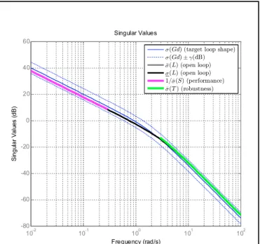
where diag stands for diagonal matrix. Figure 1 shows the singular value plot where is observed that the loop transfer function 𝐋(𝑠) approximates the desired loop shape 𝐆�(𝑠)
within certain tolerance bounds, which limit the singular values of the sensitivity function 𝐒(𝑠) and complementary sensitivity function 𝐓(𝑠), favoring performance at low frequencies and robustness at high frequencies, as described in Section 3.
Since the loop transfer function 𝐋(𝑠) approximates 𝐆�(𝑠), this
suggests that the closed loop transfer function matrix 𝐓(𝑠) from the references (𝑣���, 𝑧�,���, 𝜙���) to outputs (𝑣, 𝑧�, 𝜙)
will approximately be the following
𝐓(𝑠) = 𝐋(𝑠)�𝐈 + 𝐋(𝑠)���≈ 𝐆�(𝑠)�𝐈 + 𝐆�(𝑠)���
= diag�𝑠 + 2𝑠 + 2 ,2 𝑠 + 2𝑠 + 2 ,2 𝑠 + 2𝑠 + 22 � (43) From here one observes the following:
1. The individual transfer functions for the diagonal channels are approximated by
𝑉���(𝑠) 𝑉(𝑠) = 𝑧�,���(𝑠) 𝑧�(𝑠) = 𝜙���(𝑠) 𝜙(𝑠) ≈ 2 𝑠�+ 2𝑠 + 2 =𝑠�+ 2𝜁𝜔𝜔�� �𝑠 + 𝜔�� (44) where the last expression is the canonical form for second order systems with damping ratio 𝜁 = 0.7071 and natural frequency 𝜔�= √2 ≈ 1.4142 rad/s. From here one can
estimate the characteristics of the transient response as 𝑀�= 𝑒
��
�����≈ 0.0432 = 4.32% (45)
𝑡�=𝜁𝜔4
�= 4 s (46)
where 𝑀� is the overshoot and 𝑡� is the %2 settling time
(Ogata, 2001). This suggest that the closed loop system will track all references successfully with a small overshoot and converge to the commanded value in about 4 seconds. 2. The off-diagonal entries of 𝐓(𝑠) are roughly zero, which
indicates that the coupling between different
command-response pairs are eliminated; e.g. when the operator issues a step input from 𝑣���, this will result in an
increase in 𝑣 by 1 m/s, but the command will not result in any other unintended effects such as a change in the pitch or roll angles.
The assertions above can be verified from the closed loop step response which is shown in Figure 2. The plots in the diagonals converge to unit value in about 4 seconds with almost no overshoot and the off-diagonal plots are virtually identical to zero.
For final verification, the emergency flight control system and the nonlinear Cessna 172 model were programmed and tested under the numerical computing package MATLAB/Simulink. Numerous scenarios were studied with satisfactory results, one of which is presented here as an example. In this scenario we start with the aircraft cruising at an airspeed of 65 m/s and a height of 1000 m. Winds up to 10 m/s are typically present at these altitudes. The aircraft experiences a malfunction at 𝑡 = 10 s where the rudder servoactuator is suddenly jammed, leaving the surface stuck at 𝛿�,�����= 10∘ and unusable. The
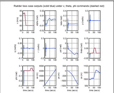
simulation results for this scenario are given in Figure 3 and Figure 4. With the rudder suddenly getting stuck, the aircraft exhibits a high rolling and yawing tendency and some tendency to pitch, as seen from the spikes and pitches in the plots for 𝑝, 𝑞, 𝑟, 𝜙, 𝜃 and 𝜓. All of this happens in a fraction of a second which is insufficient for the pilot to reach. To avoid the situation from deteriorating even further, the emergency autopilot takes over at around 𝑡 = 11 s, restores stable flight and keeps 𝑝, 𝑞, 𝑟, 𝜙, 𝜃 values close to zero while waiting commands from the operator. When the pilot feels ready they can either disable the emergency autopilot and resume manual flight, or operate the aircraft in fly-by-wire more. In this situation the latter option is attractive since the aircraft is disabled, flying sideways (𝛽 ≠ 0) and lacks a control surface. The pilot in this case restarts controlling the aircraft in fly-by-wire mode at 𝑡 = 20 s and first commands the aircraft to lower airspeed to 60 m/s between 𝑡 = 21 − 31 s. He/she then holds
Figure 1. Singular value plot for the loop-shaping controller. 10-2 10-1 100 101 102 -80 -60 -40 -20 0 20 40 60 Singular Values Frequency (rad/s) Si ngu lar V al ue s ( dB )
<(Gd) (target loop shape) <(Gd) ' .(dB) 7 <(L) (open loop) <(L) (open loop) 1=7<(S) (performance) 7 <(T ) (robustness)
Figure 2. Step response resulting of the closed-loop system with the loop-shaping controller.
0 0.5 1 1.5 From: v (m/s) cmd To : v (m /s ) 0 0.5 1 1.5 To: the ta (r ad) 0 10 20 0 0.5 1 1.5 To : p hi (ra d)
From: theta (rad) cmd
0 10 20
From: phi (rad) cmd
0 10 20
Responses to step commands for loop-shape
Time (seconds)
A
m
pl
the pitch angle 𝜃 at 3° (0.0524 rad) for some time (𝑡 = 41 − 71 s) to gain altitude, and finally keeps the roll angle 𝜙 at 3° (0.0524 rad) for a while (𝑡 = 71 − 101 s) to bank the aircraft for adjusting the flight path. From Figure 3 it is observed that the aircraft states (solid blue lines) follow the reference commands (red dotted lines) closely. One also notes that the commands only affect the intended channel and the other outputs remain virtually unchanged, e.g. the airspeed remains constant for 𝑡 = 41 − 71 s and 𝑡 = 71 − 101 s despite pitch and roll commands being issued during these intervals. The control inputs applied to the aircraft is presented in Figure 4. It can be seen that the thrust and surface deflections remain within reasonable limits at all times. Frequency spectrum amplitudes of the control inputs are also displayed in this figure. One observes from the figure that the control inputs do not contain significant power at frequencies higher than about 0.2 Hz; hence the control does not cause any sharp thrust changes or wild oscillations in control surfaces. This is a consequence of the loop-shaping design where the control action was designed to be conservative at frequencies higher than crossover frequency 𝜔�≈ 0.7464 rad/s, which
corresponds to 0.1188 Hz. Overall the flight control system maintains stable flight and responds well to commands received.
In addition to numerical simulations provided above, preliminary empirical verifications of our designs were carried out using hardware-in-the-loop (HIL) experiments, as well as flight tests using radio controlled (RC) scale models as shown in Figure 5. Due to length limitations these results are not
detailed here but the interested reader is kindly referred to (Atlas, et al., 2015), (Kasnakoglu & Kaynak, 2010), (Kaynak, et al., 2010), (Korkmaz, Ertin, Kasnakoglu, & Kaynak, 2013) and (Ertin, Korkmaz, Kaynak, & Kasnakoglu, 2013).
5. CONCLUSIONS AND FUTURE WORKS In this paper a multi-input multi-output robust control approach was investigated for distressed aircraft experiencing control loss due to surface or power failure. An accurate mathematical model of the aircraft dynamics was utilized to obtain a target aircraft behavior in the emergency situation, around which a dynamical system model was obtained through linearization. A loop-shaping controller design was seen to achieve a decent balance between performance and robustness; the former is favored for low frequencies where the model is much more accurate and the latter is preferred at high frequencies where the model is poor and noises are strong. The control design also decouples different channels successfully so that a reference command only affects its intended output. A rudder servoactuator jam scenario was presented through numerical simulations, where it was seen that the autopilot recovers level flight and responds well to fly-by-wire commands from the operator.
Future research directions include studying alternative design methods for the controllers, investigating the possibility of reducing controller size, as well as performing hardware-in-the-loop (HIL) and flight tests for verification.
Figure 3. Aircraft states (solid blue) resulting from numerical simulations of the nonlinear aircraft model in closed-loop. The reference commands are also shown in red dashed lines.
Rudder loss case outputs (solid blue) under v, theta, phi commands (dashed red)
0 50 100 58 60 62 64 66 v ( m /s) 0 50 100 -0.02 -0.01 0 0.01 0.02 al pha ( rad) 0 50 100 0 0.1 0.2 0.3 0.4 be ta ( rad) 0 50 100 -0.5 0 0.5 p ( rad /s ) 0 50 100 -0.1 -0.05 0 0.05 0.1 q ( rad/ s) 0 50 100 -0.5 0 0.5 r (r ad /s ) 0 50 100 -0.6 -0.4 -0.2 0 0.2 ps i ( ra d) 0 50 100 -0.05 0 0.05 0.1 0.15 the ta ( rad) 0 50 100 -0.3 -0.2 -0.1 0 0.1 ph i ( ra d) time (secs) 0 50 100 0 2000 4000 6000 8000 xe ( m ) time (secs) 0 50 100 -1500 -1000 -500 0 500 ye ( m ) time (secs) 0 50 100 950 1000 1050 1100 ze ( m ) time (secs)
Figure 4. Aircraft inputs (top row) and amplitude spectra (bottom row) from numerical simulations of the nonlinear aircraft model in closed-loop.
Rudder loss case inputs (blue) and spectra (red) under v, theta, phi commands
0 50 100 500 1000 1500 2000 Fx ( N ) time (secs) 0 50 100 -0.02 -0.015 -0.01 -0.005 de lta e lev at or s ( ra d) time (secs) 0 50 100 -0.1 -0.05 0 del ta ai ler on s ( rad ) time (secs) 0 50 100 0 0.05 0.1 0.15 0.2 de lta rudde r ( ra d) time (secs) -0.2 0 0.2 0 1000 2000 3000 Fx ( N ) Frequency (Hz) -0.2 0 0.2 0 0.01 0.02 0.03 del ta el ev at or s ( ra d) Frequency (Hz) -0.2 0 0.2 0 0.05 0.1 de lta a iler on s ( rad) Frequency (Hz) -0.2 0 0.2 0 0.2 0.4 0 de lta r udd er (r ad) Frequency (Hz)
Figure 5. Hardware-in-the-loop (HIL) test platform (left) and one of the radio controlled (RC) aircraft models (right) used for experimental verification of the autopilot designs.
ACKNOWLEDGEMENTS
The authors wish to thank the Scientific and Technological Research Council of Turkey (TUBITAK) for funding this research under project number 113E581. The authors are also grateful to Dr. Marc Rauw, the author of The Flight Dynamics and Control (FDC) toolbox and Dr. Giampiero Campa, the author of the Airlib toolbox. We also thank the members of the TOBB ETU Unmanned Air Vehicles Laboratory for carrying out the HIL simulations and flight tests, and to TOBB ETU Libraries for proving electronic, printed and software resources that have rendered this study possible.
REFERENCES
Atlas, E., Erdoğan, M. İ., Ertin, O. B., Guclu, A., Saygı, Y. E., Kaynak, U., & Kasnakoglu, C. (2015). Hardware-in-the-loop Test Platform Design for UAV Applications. Applied Mechanics and Materials, Manufacturing Science and Technology( VI), 681.
Belcastro, C. M., & Foster, J. V. (2010). Aircraft loss-of-control accident analysis. Proceedings of AIAA Guidance, Navigation and Control Conference. Toronto, Canada. Belcastro, C. M., Groff, L., Newman, R. L., Foster, J. V.,
Crider, D. A., Klyde, D. H., & Huston, A. M. (2014). Preliminary analysis of aircraft loss of control accidents: Worst case precursor combinations and temporal sequencing. AIAA Guidance Navigation, and Control Conference. National Harbor, MD.
Blakelock, J. H. (1991). Automatic control of aircraft and missiles. John Wiley and Sons.
Choi, B., Kang, S., Kim, H. J., Jun, B. E., Lee, J. I., Tahk, M. J., & Park, C. (2012). Roll-pitch-yaw integrated μ-synthesis for high angle-of-attack missiles. Aerospace Science and Technology, 23(1), 270-279.
Ertin, O. B., Korkmaz, H., Kaynak, U., & Kasnakoglu, C. (2013). Hardware-in-the-Loop Test Platform for a Small Fixed Wing Unmanned Aerial Vehicle Embedded Controller. The 32nd IASTED International Conference on Modelling, Identification and Control (MIC 2013). Innsbruck, Austria.
Etkin, B., & Reid, L. D. (1996). Dynamics of flight: stability and control (3rd ed.). New York: Wiley.
Fletcher, R. (1987). Practical Methods of Optimization. New York: John Wiley and Sons.
Gero, D. (2013). Aviation disasters: the world's major civil airliner crashes since 1950. The History Press.
Gill, P. E., Murray, W., Saunders, M. A., & Wright, M. H. (1984). Procedures for optimization problems with a mixture of bounds and general linear constraints. ACM Transactions on Mathematical Software (TOMS), 10(3), 282-298.
Gill, S. J., Lowenberg, M. H., Neild, S. A., Crespo, L. G., Krauskopf, B., & Puyou, G. (2015). Nonlinear Dynamics of Aircraft Controller Characteristics Outside the Standard Flight Envelope. Journal of Guidance, Control, and Dynamics., 38(12), 2301-2308.
Kasnakoglu, C., & Kaynak, U. (2010). Automatic Recovery and Autonomous Navigation of Disabled Aircraft After Control Surface Actuator Jam. AIAA Guidance, Navigation and Control Conference. Toronto, Canada. Kaynak, U., Akbaba, R., Kibar, A., Kasnakoğlu, C.,
Sezer-Uzol, N., Güleç, E., Solmaz, M. (2010). Design and Manufacture of a Fuel Cell Powered Unmanned Air Vehicle. International Unmanned Vehicles Workshop UVW2010. Istanbul, Turkey.
Korkmaz, H., Ertin, O. B., Kasnakoglu, C., & Kaynak, U. (2013). Design of a Flight Stabilizer System for a Small Fixed Wing Unmanned Aerial Vehicle Using System Identification. IFAC Workshop on Advances in Control and Automation Theory for Transportation Applications (ACATTA 2013), (pp. 145-149). Istanbul, Turkey. Liu, H., Li, D., Kim, J., & Zhong, Y. (2014). Real-Time
Implementation of Decoupled Controllers for Multirotor Aircrafts. Journal of Intelligent & Robotic Systems, 73(1-4), 197-207.
Nelson, R. C. (1998). Flight stability and automatic control. McGraw Hill.
Ogata, K. (2001). Modern control engineering. Prentice Hall PTR.
Rauw, M. (2001). FDC 1.2 - A Simulink Toolbox for Flight Dynamics and Control Analysis. Haarlem, The
Netherlands.
Schittkowski, K. (1986). NLPQL: A FORTRAN subroutine solving constrained nonlinear programming problems. Annals of operations research, 5(2), 485-500.
Stevens, B., & Lewis, F. (2003). Aircraft Control and Simulation (2nd ed.). Wiley-Interscience.
Yang, C. D., & Liu, W. H. (2003). Nonlinear H-infinity decoupling hover control of helicopter with parameter uncertainties. American Control Conference, (pp. 3454-3459).
Yu, X., & Jiang, J. (2012). Fault-tolerant flight control system design against control surface impairments. IEEE Transactions on Aerospace and Electronic Systems, 48(2), 1031-1051.