A 60 GHz Beam-Steering Reconfigurable Antenna
A. Khalat, Md. A. Towfiq and B. A. Cetiner Electrical and Computer Engineering
Utah State University Logan, Utah
¨
O. Ceylan and N. Biyikli
National Nanotechnology Research Center Bilkent University
Turkey
Abstract—We present the design, microfabrication, and char-acterization of a multifunctional reconfigurable antenna (MRA) with beam steering capability operating at 60 GHz band (59-66 GHz). The MRA provides 3 different beam directions pertaining to: θ ∈ {−300, 00, 300}; φ = 900
based on reconfigurable para-sitic layer approach. The structure consists of three layers namely, feed, driven antenna and reconfigurable parasitic layers. The first two layers use RF and microfabrication process compatible quartz (εr = 3.9, tanδ = 0.0002) substrate while parasitic
layer is formed on a low-cost pyrex (εr = 4.9, tanδ = 0.01)
material with air cavities formed underneath. The upper surface of pyrex has 3x3 rectangular shaped metallic pixels, four of which are interconnected by means of switching. By judiciously controlling the switch status the beam-steering is accomplished. The simulated impedance and gain characteristics show ∼ 15% bandwidth over which the maximum realized gain remains relatively flat around ∼ 7.2 dB for all modes of operation.
I. INTRODUCTION
The demand of high data rate has been frantically increas-ing in the recent years due to expansion of smart devices and cloud-based applications. In response, the development of wireless communication systems operating at higher fre-quencies such as mm-Waves (WiGig, 60GHz) has become a popular research area of interest for both academy and industry [1]. While this mm-Wave frequency range is excellent in offering very broad bandwidth (BW) and high data rates, the associated propagation losses are too severe to ignore. This makes necessary to develop antenna systems with high gain and beam-steering capability. Phased array antennas with excellent beam-steering capability and high gain can provide the desired antenna properties [2]. This, however, comes with high cost and complexity, which may be prohibitive for some commercial wireless communication applications. The MRA with beam-steering capability presented in this paper has the potential to be the main building block of a new class of mm-Wave antenna array with low-cost and complexity [3]. The main novelty of such a reconfigurable antenna array is its variable element factor which is fixed for legacy phased array antennas. This work presents the design, manufacturing and initial characterization of a single element MRA. This MRA structure takes advantage of a low-cost and microfabrication process compatible pyrex material, which is used to create reconfigurable parasitic layer.
II. ANTENNADESIGN ANDFABRICATION
The MRA structure as shown in Fig. 1 and Fig. 2, is designed to reconfigure the main beam direction of the
ra-Fig. 1. 3-D Schematic of the designed MRA (for illustration purpose the layers are suspended on top of each other), (1, 2, 3, 4 denote switchs location)
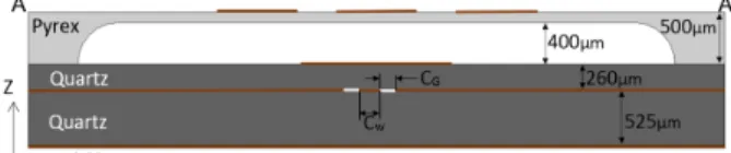
Fig. 2. A-A’ Cross section view of the pattern reconfigurable antenna.
diation pattern into three different directions pertaining to: θ ∈ {−300, 00, 300}; φ = 900 over 59 - 66 GHz band.
The antenna structure consists of three layers namely, the feed, driven antenna and reconfigurable parasitic layers with respective thicknesses of 525µm, 260µm and 500µm. The bottom and middle layers which house the CPW-fed loop and driven patch antenna, respectively, are formed on quartz substrates which provides good RF properties and micro-fabrication process compatibility. The CPW-fed loop couples the EM energy to the patch antenna, which results in broad BW. The formation of copper metalization for both layers are implemented by basic microfabrication processes of thin layer metal deposition via electron-beam and lift-off tech-niques. The top layer is made out of low cost pyrex material which is thinned down to 100µm by using standard chemical wet-etch process. The upper surface of this layer has 3x3 metallic rectangular shaped pixels, which are connected or disconnected by means of switching, where for the sake of simplicity these interconnections are employed as perfect short and open circuits in this work. Among the total of twelve interconnections between adjacent pixels only four need to
1279
be controlled to accomplish the targeted three different beam-steering directions. This layer is solely used for mechanical support for reconfigurable pixel surface and the air cavity formed underneath with a thickness of 400µm serves as low dielectric constant and low loss medium. The design parameters are jointly optimized to simultaneously yield broad impedance BW, high gain and desired beam steering capabil-ity. The optimized design parameters of the patch element, CPW-fed loop, and the reconfigurable parasitic layer which are obtained by full-wave EM simulations are provided in Table I.
TABLE I
THE CRITICAL DESIGN PARAMETERS OF THE MMWAVEMRA (ALL DIMENSIONS ARE INmm).
P il 0.8 P iw 0.8 Gl 0.4 Gw 0.4
Pw 1 Ll 1 CG 0.02 Cw 0.191
Pl 1 Lw 1.2 Lt 0.02 St 0.1
III. RESULTS ANDCHARACTERIZATION
The top view of the MRA showing switch locations is de-picted in Fig. 1. A multi-objective genetic algorithm optimiza-tion [4] in conjuncoptimiza-tion with full-wave analysis is used to design the reconfigurable parasitic surface. Results indicate that only four out of twelve interconnections need to be controlled in order to achieve targeted three beam steering directions pertaining to: θ ∈ {−300, 00, 300}; φ = 900over 59- 66 GHz
band. The corresponding optimized switch configurations are given in Table II.
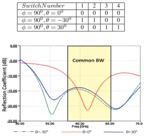
The simulated reflection coefficients for all the three modes of operation are given in Fig. 3. The intersection of three individual reflection coefficients indicate a common BW of 6 GHz covering 59-65 GHz band. The total realized gain patterns in Y-Z plane corresponding to each mode of operation at 60 GHz are shown in Fig. 4. The maximum realized gain
TABLE II
THE SWITCH STATUS CORRESPONDING TO THREE BEAM STEERING DIRECTIONS(0 = OFF, 1 = ON).
SwitchN umber 1 2 3 4 φ = 900, θ = 00 0 0 0 0
φ = 900, θ = −300 1 1 0 0 φ = 900, θ = 300 0 0 1 1
Fig. 3. Simulated reflection coefficient of the MRA.
values in the steered beam directions are all above ∼ 7 dBi. The realized gain values for all modes of operation over the entire 59 - 64 GHz band are in the range ∼ 6.5 − 7.9 dB as shown in Fig. 5.
Fig. 4. Simulated total realized gain plots of the MRA in φ = 900 (Y-Z) plane.
Fig. 5. Simulated realized gain values over 59-64 GHz band for three beam-steering directions θ ∈ {−300, 00, 300}; φ = 900(Y-Z) plane.
IV. CONCLUSION
In this paper, an MRA with beam steering capability operat-ing at mm-Wave range is designed and simulated. The simula-tion results for different operasimula-tional modes indicates a realized gain around 7 dBi covering 59-64 GHz band. The low-cost and microfabrication compatibility of this MRA makes it a useful candidate for mm-Wave application. Our current efforts are concentration on replacing perfect short/open connections with p-i-n diodes and performing measurements.
REFERENCES
[1] R. Daniels and R. Heath, “60 ghz wireless communications: emerging requirements and design recommendations,” Vehicular Technology Mag-azine, IEEE, vol. 2, no. 3, pp. 41–50, Sept 2007.
[2] R. J. Mailloux, “Phased array antenna handbook,” Boston, MA: Artech House, 1994., 1994.
[3] Z. Li, D. Rodrigo, L. Jofre, and B. Cetiner, “A new class of antenna array with a reconfigurable element factor,” Antennas and Propagation, IEEE Transactions on, vol. 61, no. 4, pp. 1947–1955, April 2013.
[4] K. Deb, A. Pratap, S. Agarwal, and T. Meyarivan, “A fast and elitist multiobjective genetic algorithm: NSGA-II,” IEEE Transactions on Evo-lutionary Computation, vol. 6, no. 2, pp. 182–197, 2002.