European Collaboration in Conformal Antenna Research
Zvonimir Sipus
♠, Patrik Persson
♣, Maria Lanne
♥, Marcos Heckler
♦, Stefano Maci
○,
José Luis Masa-Campos*, Peter Knott
∆, Vakur Ertürk
#and Guy Vandenbosch
†♠University of Zagreb, Croatia, E-mail: [email protected]
♣Ericsson AB, Antenna Research Center, Sweden, E-mail: [email protected] ♥
Saab Microwave Systems, Sweden, E-mail: [email protected]
♦German Aerospace Center, Germany, E-mail: [email protected] ○University of Siena, Italy, E-mail: [email protected]
*Polytechnic University of Madrid, Spain, E-mail: [email protected]
∆Research Institute for High Frequency Physics and Radar, Germany, E-mail: [email protected] #Bilkent University, Turkey, E-mail: [email protected]
†Catholic University of Leuven, Belgium, E-mail: [email protected]
ABSTRACT: The work carried out within Work Package 2.4-3 of the EU network “Antenna Centre of Excellence”
(ACE) is presented in this paper. This work package is concerned with structuring research on conformal antennas. In more details, the work is focused on the problems associated with full benchmarking of conformal antennas, on development of hybrid programs for analyzing different classes of conformal antennas, and on investigation of properties of algorithms for optimizing beam synthesis and beam-steering for conformal arrays.
1. INTRODUCTION
The shape of conformal antennas is mainly determined by considerations other than electromagnetic. Possible design guidelines can be needed aerodynamic or hydrodynamic shape of antenna, coverage reason or aesthetic reason. The shape of non-planar antenna can be also determined with specific electromagnetic reasons like coverage requirements. For example, arrays on cylindrical structures offer a possibility either to create directed beams in arbitrary direction in horizontal plane, or to create an omnidirectional pattern. In similar way spherical arrays have the capability of directing single or multiple beams through a complete hemisphere. Such properties make conformal antennas attractive candidates for future antenna systems where a variety of beam-forming and beam-steering capabilities will be needed, and where the antennas will be integrated in the surfaces of different vehicles or platforms. A modern aircraft, for example has many antennas protruding from its body, for navigation, various communication systems, instrument landing systems, radar altimeter etc. There can be as many as 40 different antennas (or even more), and integrating these antennas into the aircraft skin is highly desirable.
2. STRUCTURING RESEARCH
From the beginning of the ACE network, the basic objective was to better structure the ongoing research on conformal antennas, dispersed in several European
universities and industrial research centres. In more details, the objectives in this work-package are:
• sum up advantages and critical items for various conformal antennas:
• structure continued research in direction of the most useful antenna architectures & geometries, • select benchmarking structures, and test the
accuracy of software developed for designing conformal antennas
• help students/PhDs exchange between various European academies and companies.
The work is split into 3 topics:
• Full benchmarking of conformal antennas • Development of “new” hybrid programs
• Properties of algorithms for optimizing beam synthesis and beam-steering. of conformal arrays. Full benchmarking of conformal antennas.
Nowadays, design of antennas relies mostly on accuracy and speed of used electromagnetic software. There are two criteria in selecting the appropriate software tool: to use general programs like FDTD or FEM, or to use specialized programs developed for specific geometry. The conformal antenna structures are usually large in terms of the wavelength, and consequently the needed computer time can be very large if a general program is selected for design procedure. It is more convenient to use specialized
programs for specific conformal geometries that are fast and in some cases more accurate since they explicitly take into account the antenna geometry. Therefore, the usual procedure in designing conformal antennas is first to use a specialized program for a specific type of conformal antennas, and then to use some general program for designing fine details. Before designing the antenna, the designer should know what is the accuracy of the software proposed for the design process. The practice has shown that even the expensive commercial software packages can easily introduce a large error, i.e. the obtained design is useless in that case. Furthermore, working with commercial CAD tool requires costly training sessions and long-term experience. The best performances of commercial software tool can be obtained only by experienced engineers. In other words, it is not acceptable to waste a couple of weeks before it is discovered that the antenna structure is treated in a wrong way, or that the software tool cannot correctly handle the considered structure! Therefore, maybe the best way to test if one program is suitable for designing some particular antenna is to analyse some benchmarking structure that is similar to the considered antenna. In that way the engineers will see if the proposed software is accurate enough, and if the software is used in a proper way.
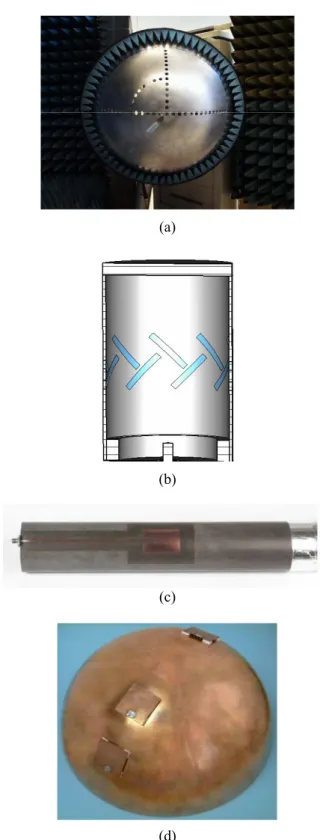
The selected structures for the benchmarking process in year 2007 are given in Figure 1. The structures cover cylindrical, spherical and parabolic conformal geometries. As radiating elements, microstrip patch antennas and waveguide openings are proposed. Therefore, we believe that we have covered a large group of conformal antennas, i.e. most of the developed conformal antennas have similarity with at least one of the proposed structures.
The goal of the benchmarking activity is twofold. First, we would like to fully describe the proposed benchmarking structures in order to enable antenna engineers simply to check the considered programs. In other words, all the parameters of the considered antenna should be given, as well as the measured data (from practical reasons, the measured data should be given in the form of ASCII files). Second, we would like to explore what is the accuracy of the developed software for analyzing conformal antennas. With this, possible users will see if the developed software fulfils their needs (accuracy, speed).
As an example we consider a parabolic waveguide array from Figure 1.a. The array is a doubly curved conformal testbed antenna with apertures in X-band. It consists of dielectric filled circular waveguide elements in a surface shaped as a circular paraboloid.
(a)
(b)
(c)
(d)
Figure 1. The selected structures for benchmarking process in 2007; (a) parabolic waveguide array (Saab Microwave Systems AB), (b) Circular-cylindrical waveguide array with omnidirectional radiation pattern (University of Madrid), (c) cylindrical axially-polarized patch antenna (Deutsches Zentrum für Luft- und Raumfahrt e.V), (d) spherical patch antenna (University of Zagreb)
The diameter of the surface is approximately 600 mm and the depth is approximately 175 mm [see Fig. 1(a)], extended with a conical sheet of metal to gain extra space for absorbers at the edge. The antenna elements are circular waveguide-fed apertures filled with Rexolite (εr = 2.53) with a diameter of 14.40 mm. In
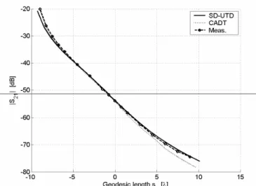
Figure 2. the measured results of mutual coupling in the E-plane are compared with the calculated results obtained by UTD program (CADT, Royal Institute of Technology, Sweden) and by the hybrid SD-UTD program described in the next section.
Figure 2. The mutual coupling in the E plane for the array of aperture elements on a PEC circular paraboloid.
Development of “new” hybrid programs.
One of the activities inside the Work Package 2.4-3 is to join research activities of different groups. For example, different software packages can be combined in order to take advantages of different analysis methods. Example of such a project is the one made by Royal Institute of Technology, Sweden, and University of Zagreb, Croatia, where two methods for analyzing conformal antennas (spectral domain method (SP) and uniform theory of diffraction (UTD)) are combined resulting in a hybrid code: SD-UTD analysis method.
In short, UTD method is advantageous when large metal structures are analyzed. Spectral-domain method is advantageous when multilayer cylindrical or spherical structures are analyzed. On the other hand, the spectral-domain method has numerical difficulties when it is applied for analyzing large structures, and UTD method is not suitable for structures with small radius and for structures that include multilayer dielectric layers.
To illustrate the concept, let’s consider a waveguide-fed aperture array embedded in a multilayer
circular-cylindrical structure. The moment method matrix terms needed to be calculated are of the form given in eq. (1) (details are given in [2] and [3]):
z z j z z i ij M m k Gmk M mk dk Y ~( , )~( , )~ ( , ) 4 1 2
∑ ∫
∞ ∞ − ∞ ∞ − − − = π . (1)By applying the asymptotic extraction technique we get:
∫
∫
∑∫
− − + ⎥⎦ ⎤ ⎢⎣ ⎡ − − − = ∞ ∞ − ∞ ∞ − function basis j asym i function test z z j z asym z z i ij dS dS z M z z G z M dk k m M k m G k m G k m M Y ' ) ' ,' ( ) ' ,' ( ) , ( ) , ( ~ ) , ( ~ ) , ( ~ ) , ( ~ 4 1 2 φ φ φ φ π (2) The first term in eq. (2) is calculated using spectral domain approach, while the second term is calculated using UTD. Since it is difficult to analyze multilayer structures using UTD (a single layer can be analyzed as described in [4]), we assume a homogeneous media with permittivity equal to the permittivity value of the first layer next to the PEC (if the source above the PEC is considered, then the average value of the two nearby layers surrounding the source is used). Consequently, we have combined a robust multilayer solver (spectral domain approach) with the simplicity of a high frequency approach (UTD) suitable for the analysis of electrically large surfaces.This idea can be expanded further for non-canonical surfaces such as elliptic or parabolic structures. This is due to the fact that the UTD solution developed by Pathak et al.[5] is valid for arbitrary convex surfaces. To be able to use the spectral domain part of the hybrid solution we approximate the analyzed structure with the most appropriate canonical one using the equivalent radius of curvature approach.
The first step is determining the local radius of curvature for the analyzed structure. This local radius is the key parameter in the hybrid method when analyzing the radiation properties - we simply replace the analyzed structure with an appropriate canonical one having a radius equal to the local radius of the structure at the source. However, when considering the mutual coupling between two elements a more thorough analysis is needed. In this case we need to calculate an equivalent radius that incorporates the information about the curvature behavior and arc length between the source and observation points. This equivalent radius of curvature is obtained from the UTD solution, and calculated using the generalized Fock parameter given by
( )
[
]
∫
− ⋅ ⎟ ⎠ ⎞ ⎜ ⎝ ⎛ = Q Q loc t dt k ' 3 / 2 3 / 1 ' ) ' ( 2 ρ ξ , (4)where t' is the local spatial coordinate in the ray direction, Q’ and Q are source and observation points on the curved surface, ρloc is the local radius and k is
the wave number. Equivalent radius is now calculated using the Fock parameter and the geodesic path length
l as 2 / 3 3 / 1 2 ⎥⎥⎦ ⎤ ⎢ ⎢ ⎣ ⎡ ⋅ ⎟ ⎠ ⎞ ⎜ ⎝ ⎛ = ξ l k Re . (5)
Note that in the analysis presented here only the shortest (single) geodesic is included.
The accuracy of the method is illustrated in Figure 2 where we have analyzed mutual coupling between apertures on parabolic surface. It can be seen that practically there is no difference between hybrid SD-UTD method and the SD-UTD method, and that there is a good agreement with the measurements.
Beamforming in conformal arrays.
In recent years there has been an explosive growth in the number of wireless users, particularly in the area of mobile communication. In the future, wireless mobile systems will be more sophisticated and more widespread. This growth has triggered an enormous demand not only for capacity but also for better coverage and higher quality of service. Unlike wireless systems in the past, which used fixed antenna systems, the systems of today use smart or adaptive arrays that are dynamically able to adapt to the changing environment and traffic requirements. Furthermore, future antenna systems will also be integrated in the surfaces of different vehicles or platforms, i.e. conformal antennas.
The aim of this work is to gain knowledge about different smart antenna algorithms, especially when applied to conformal array antennas. First, we have considered direction of arrival (DOA) estimation. Such algorithms must be used in the first place in order to find out the interfering directions and the direction of the desired signal. When known, the beamformer steer the radiation in the particular direction of the desired signal and place the nulls in the interfering directions.
We have considered both linear and circular arrays, as well as isotropic and directional elements. As an example in Fig. 3 it is shown DOA estimation when the considered array consists of dipoles above a PEC cylinder. Therefore, the element pattern is assumed to
be 1 cos+ θ. Note, the effect of creeping waves in the
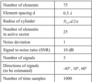
shadow region is not included in the analysis. Parameters of the array and incoming signals are given in Table 1. As illustrated here, the MUSIC algorithm
works well in all cases and it is possible to find out the direction of arrival of incoming signals.
Number of elements 75 Element spacing d 0.5 λ Radius of cylinder Ncyl d/2π
Number of elements
in active sector 25 Noise deviation 1 Signal to noise ratio (SNR) 10 dB Number of signals 3 Directions of signals
(to be estimated) -45°, 10°, 60° Number of time samples 1000
Table 1. DOA estimation; parameters of waveguide array and incoming signals.
Figure 3. The MUSIC spectrum for a circular array of dipoles above a PEC cylinder.
As an example of applying adaptive beamforming to conformal arrays, we have considered the Capon’s algorithm. Parameters of the array and incoming signals are given in Table 2. As seen in Fig. 4, the Capon’s algorithm determines the weights for determining the main beam in the desired direction and ensures that local minima are placed at the jammer directions. It could be noted however, that the use of an active sector for the cylindrical array decreases the performance when using directive elements.
Number of elements 29 Element spacing d 0.5 λ Radius of cylinder Ncyl d/2π
Number of elements
in active sector 9 Noise deviation 1 Number of signals 3 Directions of desired signal -45° Directions of jammers 10°, 60° Number of time samples 1000
Table 2. Beamforming using Capon’s algorithm; parameters of waveguide array and incoming signals.
REFERENCES
1. L. Josefsson and P. Persson, Conformal Array
Antenna Theory and Design, Wiley - IEEE Press,
2006.
2. R.F. Harrington, Time harmonic electromagnetic
fields, Prentice-Hall, 1961.
3. Z. Sipus, M. Lanne, and L. Josefsson, “Moment method analysis of circular-cylindrical array of waveguide elements covered with a multilayer radome,” IEE Proceedings Part H, Vol. 153, pp. 29-37, Feb. 2006.
4. P. Persson and R. G. Rojas, “High-frequency Approximation for Mutual Coupling Calculations Between Apertures on a Perfect Electric Conductor Circular Cylinder Covered with a Dielectric Layer: Nonparaxial Region,” Radio Sci., Vol. 38, No. 4, 1079, 2003.
5. P.H. Pathak, N. Wang, W.D. Burnside, and R.G. Kouyoumjian, “A uniform GTD solution for the radiation from sources on a convex surface,” IEEE
Trans. Antennas and Propagat., vol. 29, pp. 609-622,
July 1981.
6. P. Persson and L. Josefsson, “Calculating the Mutual Coupling Between Apertures on a Convex Circular Cylinder Using a Hybrid UTD-MoM Method,” IEEE Trans. Antennas Propagat., Vol. 49, No. 4, pp. 672-677, April 2001.
Figure 4. The Capon beam pattern for a circular array of dipoles above a PEC cylinder.