Models and Modeling:
Be Careful and Use Your Imagination
L.
Cern Goknar
Do~u§ University, Electronics and Communications Engineering Department Zeamet Sokak 21, Aciboademn - Kadik~y, 34722 Istanbul - Turkey
Tel: +90 (216) 544 55 55/1313; Fax: +90 (216) 544 55 35; E-mail: [email protected]
Abstract
When not soldering, engineers continuously deal with models when analyzing, designing, and implementing. There are two phases in modeling: utilization, and creation. Model utilization is common practice, and does not necessitate further comment other than "make the right choice and use the model carefully." The tutorial addresses the first phase briefly and shows how erroneous results may occur when care is not exercised. The second phase is much more subtle: it requires delicate measurements, extreme perception, and/or excellent imagination. Memnristors and memnristive systems, a perfect illustration of "using imagination," are presented and discussed at length. Their recent realization as a nano-chip by HP is a very good example of "history repeating itself," and proof of how "an electrical element that was postulated almost fifty years ago to exist, became a reality." The tutorial concludes with some reactions to and comments about this new device.
Keywords: Modeling; circuit modeling; electromagnetic model; MOS devices; operational amplifiers; Kirchoff s laws; memristor; memnristive systems
1. Introduction
W
hen analyzing, designing, calculating, simulating, etc., engi-neers always use models. The crucial point here is to choose the right model for the physical device under consideration. The same physical device may be assigned different models, with an increasing order of complexity, depending on the conditions (fre-quency range, ambient temperature, amplitude of physical signals, etc.) under which it will operate, as the following two examples demonstrate.Example 1. Depending on its operating point and frequency of operation, a single MOS transistor has several models. These range from a simple switch, to equivalent circuits containing dependent sources, capacitors (increasing in number as the fre-quency increases), diodes, to sophisticated simulation models, like BSIM.
Example 2. A simple interconnection wire, which is consid-ered to be a short circuit between the nodes it joins, with increasing frequency becomes a simple capacitor, an RC section, an RLC sec-tion, and then several sections. It finally (?) becomes an abstract two-port, with a mathematical expression like the Telegrapher's Equation, or some other input-output behavior.
So, the challenging question for an engineer becomes, "Which model to use, when?" No easy answer exists, other than "experience." One may wonder, "Why not use the most sophisti-cated model?" The simple reply is that to use a more-complex model than needed may consume huge amounts of computational time and, more importantly, obscure the insight to the problem. IEEE Antennas and Propagation Magazine, Vol. 50, No. 5, October 2008
hin this tutorial, two issues related to models and modeling will be addressed:
*To use existing models correctly (be careful),
* To create new models when existing models do not sat-isfy needs (use your imagination).
2. Quiz 1: Careful Use of Models
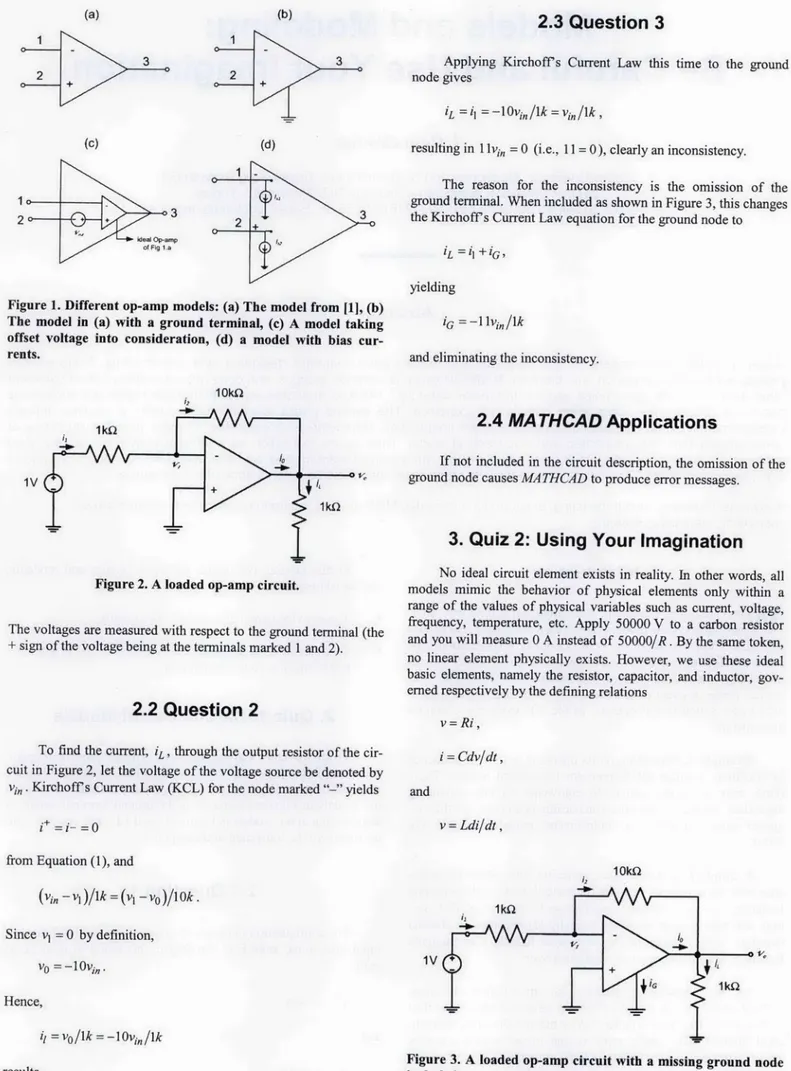
To answer Quiz I in the last issue, different models of opera-tional amplifiers (op-amps) will be visited first, to further illustrate the issue of increasing complexity [I]. The only difference between the models in Figures I a and lb is the ground terminal, which is also missing in the models in Figures Ic and Id. That this oversight is critical will be illustrated in the sequel.2.1 Question
1
The configuration in Figure lb is called an "ideal differential-input operational amplifier" (op-amp in this issue). It is modeled with
v+ -V =0 (I a)
and
i+ =i =0. (lb)
(a)(b
I
(c) )(d)
of Fig i..
Figure 1. Different op-amp models: (a) The model from ill, (b) The model in (a) with a ground terminal, (c) A model taking offset voltage into consideration, (d) a model with bins cur-rents.
101<0
IV
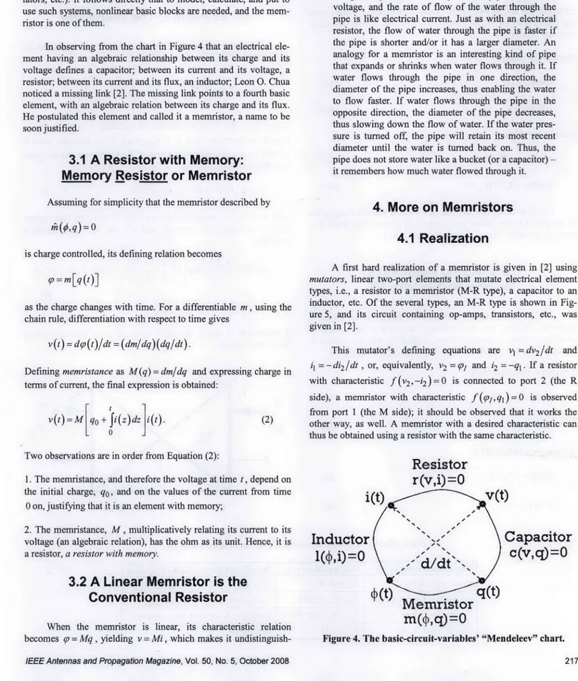
Figure 2. A loaded op-amp circuit.
The voltages are measured with respect to the ground terminal (the + sign of the voltage being at the terminals marked 1 and 2).
2.2 Question 2
To find the current, iL, through the output resistor of the cir-cuit in Figure 2, let the voltage of the voltage source be denoted by vi,,. Kirchoff's Current Law (KCL) for the node marked "-" yields
(b)
and
v = Ldi/dt,
from Equation (1), and
1 Okf2
(vi.2 -vi))/k=(vi -vo)/l0k. Since v, = 0 by definition, V0 = -I 0i',. Hence, results. 216 IV
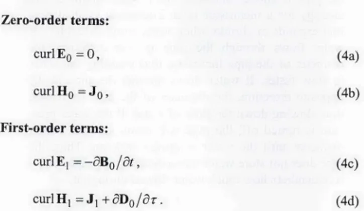
Figure 3. A loaded op-amp circuit with a missing ground node included.
IEEE Antennas and Propagation Magazine, Vol. 50, No. 5, October 2008
2.3 Question 3
Applying Kirchoff's Current Law this time to the ground node gives
resulting in 1 lvrn, = 0 (i.e., 11 = 0), clearly an inconsistency. The reason for the inconsistency is the omission of the ground terminal. When included as shown in Figure 3, this changes the Kirchoff's Current Law equation for the ground node to
'L =' +G
yielding
iG =r -1 lvin Ilk
and eliminating the inconsistency.
2.4 MATHCAD Applications
If not included in the circuit description, the omission of the ground node causes MA THCAD to produce error messages.
3. Quiz 2: Using Your Imagination
No ideal circuit element exists in reality. In other words, al models mimic the behavior of physical elements only within a range of the values of physical variables such as current, voltage, frequency, temperature, etc. Apply 50000 V to a carbon resistor and you will measure 0 A instead of 500001R. By the same token, no linear element physically exists. However, we use these ideal basic elements, namely the resistor, capacitor, and inductor, gov-erned respectively by the defining relationsv =Ri,
as basic building blocks that are capable of modeling almost all existing passive electronic devices. However, unfortunately, all these models are linear. On the other hand, linearity is a highly desirable property, as it simplifies models, produces linear equa-tions with relatively easy solution methods, and offers several analysis/design properties.
On the other hand, nonlinear basic elements cannot be avoided since i) the world is highly nonlinear; and ii) nonlinearity is much exploited in many applications (clippers, rectifiers, modu-lators, etc.). It follows directly that to model, calculate, and put to use such systems, nonlinear basic blocks are needed, and the mem-ristor is one of them.
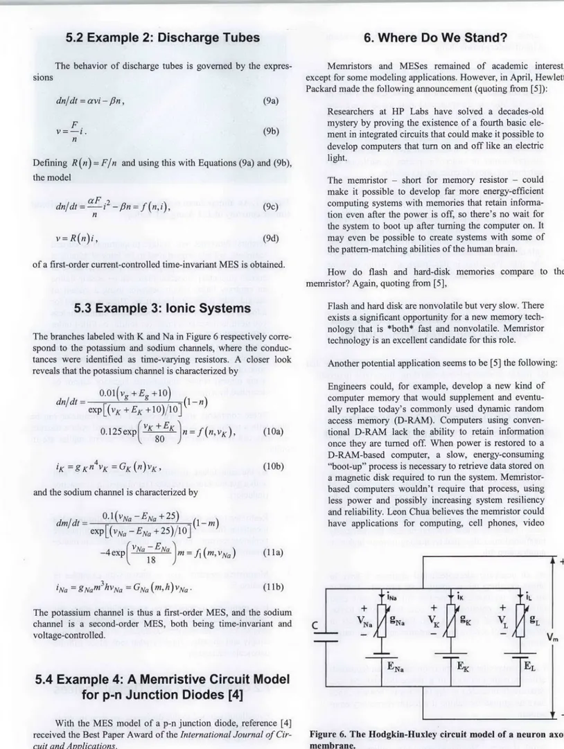
In observing from the chart in Figure 4 that an electrical ele-ment having an algebraic relationship between its charge and its voltage defines a capacitor; between its current and its voltage, a resistor; between its current and its flux, an inductor; Leon 0. Chua noticed a missing link [2]. The missing link points to a fourth basic element, with an algebraic relation between its charge and its flux. He postulated this element and called it a memristor, a name to be soon justified.
3.1 A Resistor with Memory:
Memnory Rlesistor or Memristor
Assuming for simplicity that the memristor described byis charge controlled, its defining relation becomes ip = M[q (t)]
as the charge changes with time. For a differentiable m, using the chain rule, differentiation with respect to time gives
v (t) = dp,(t)/dt = (dm/dq) (dq/dt).
Defining memristance as M(q) = dm/dq and expressing charge in terms of current, the final expression is obtained:
v(t)=M[qo + i(z)dz i(t). (2)
able from an ordinary resistor. That is probably why it had not been postulated earlier, since for a long period of time, only linear circuits were dealt with.
3.3 An Analogy for the Memristor [6]
A common analogy for a resistor is a pipe that carries water. The water itself is analogous to electrical charge, the pressure at the input of the pipe is similar to voltage, and the rate of flow of the water through the pipe is like electrical current. Just as with an electrical resistor, the flow of water through the pipe is faster if the pipe is shorter and/or it has a larger diameter. An analogy for a memiristor is an interesting kind of pipe that expands or shrinks when water flows through it. If water flows through the pipe in one direction, the diameter of the pipe increases, thus enabling the water to flow faster. If water flows through the pipe in the opposite direction, the diameter of the pipe decreases, thus slowing down the flow of water. If the water pres-sure is turned off, the pipe will retain its most recent diameter until the water is turned back on. Thus, the pipe does not store water like a bucket (or a capacitor)-it remembers how much water flowed through -it.
4. More on Memnristors
4.1 Realization
A first hard realization of a memnristor is given in [2] using mutators, linear two-port elements that mutate electrical element types, i.e., a resistor to a memristor (M-R type), a capacitor to an inductor, etc. Of the several types, an M-R type is shown in Fig-ure 5, and its circuit containing op-amps, transistors, etc., was
given in [2].
This mutator's defining equations are v, = dv2/Idt and =. -di 2/Idt , or, equivalently, v2 = ip and i2 = -ql . If a resistor with characteristic f (v2, -i2 ) = 0 is connected to port 2 (the R
side), a memnristor with characteristic f (Vq~, ) = 0 is observed from port 1 (the M side); it should be observed that it works the other way, as well. A meniristor with a desired characteristic can thus be obtained using a resistor with the same characteristic. Two observations are in order from Equation (2):
1. The memnristance, and therefore the voltage at time t, depend on the initial charge, q0, and on the values of the current from time
0 on, justifying that it is an element with memory;
2. The meniristance, M, multiplicatively relating its current to its voltage (an algebraic relation), has the ohm as its unit. Hence, it is a resistor, a resistor with memory.
3.2 A Linear Memristor is the
Conventional Resistor
When the memristor is linear, its characteristic relation becomes q.' = Mq , yielding v = Mi, which makes it undistinguish-IEEE Antennas and Propagation Magazine, Vol. 50, No. 5, October 2008
Resistor
r(v,i) =0
i(t)
Inductor
1(4,i)=0
Capacitor
c(v,q)=0
Memristor
ml(4,q)=0
Figure 4. The basic-circuit-variables' "Mendeleev" chart.
4.2 Electromagnetic Interpretation [2]
Starting with Maxwell's equations in differential form, curl E = - 4B/8t arnd curl H = J + aID/Ot, the change of variables
I= cur results in curliE =- a~a
(3) curl H
= J + aD/ar.
Expanding E and H with respect to a in Equation (3) and
equat-ing like powers of ax, by keeping the first two terms, four equa-tions are obtained:
Zero-order terms: curl E0 = 0, (4a) curl H0 = J0, General MES: dx/dt = f(x, u), (5e) (5f) y =G(x,u).
To motivate the introduction of MES, some erroneously classified devices will be presented.
5.1 Example 1: The Thermistor
Thermistors, viewed as linear resistors with temperature-varying resistance, obey the equation
v = P0(TO) exp [ 1-I)iRTi (6)
(4b)
First-order terms:
curiE1 =-aB/olt,
curl H, = J, +aD0
/ar.
(4c) (4d) In a physical device, depending on which terms are negligible as compared to the others, one of the well-known three basic ele-ments is obtained. This is summarized in Table 1.
Generalizing Memristors:
Memnristive Systems [3]
The inclusion of a memristor, even though it was useful in modeling devices, was not sufficient to cover a large class of existing systems. A generalization, defined by the expressions in Equation (5), was introduced with MEmristive Systems (MES):
Current-controlled MES: dx/dt = f(x, i), v =R (X,i) I Voltage-controlled MES: dx/dt-=f (x, v), i=G(x,v), (5a) (5b)
where To is the absolute ambient temperature, T is the tempera-ture of the thermistor, and 81 is a constant. T, on the other hand, is related to the instantaneous power of the thermistor via the heat-transfer equation:
v-=v (t)i(t)~ = K(T- TO) +CdT/dt, (7)
with K being the dissipation constant and C being the heat
capaci-tance. Combining Equations (6) and (7), the MES description is reached.
dT/dt-
=Ro0(TO)
expFI[4
i
)1i
2
-_K(T-
TO) = f (T, i),(8)
v =R (T)i.
A thermistor is thus a first-order (dimension of the state space) MES with memory.
+
VI
(5c)
(5d)
V2
Figure 5. An M-R type mutator.
Table 1. The electromagnetic interpretation of lumped elements.
Negligible Terms in [4) Relation Between -Resulting Electromagnetic System,
First-order fields E0 and H1o Resistor
First-order magnetic field E0, El, and H0 Inductor in series with a resistor First-order electric field E0, H0 , and H1 Capacitor in parallel with a resistor
Zeroth-order fields El and H1 Memristor
218 IEEE Antennas and Propagation Magazine, Vol. 50, No. 5, October 2008
5.2 Example 2: Discharge Tubes
6. Where Do We Stand?
The behavior of discharge tubes is governed by theexpres-sions dn/dt = avi -fin, F. V =-1. n (9a) (9b) Defining R (n) = F/n and using this with Equations (9a) and (9b),
the model
dn/dt= aF. P 3n-fin=f(n, i), n
v-=R(n)i,
(9c) (9d) of a first-order current-controlled time-invariant MES is obtained.
5.3 Example 3: Ionic Systems
The branches labeled with K and Na in Figure 6 respectively corre-spond to the potassium and sodium channels, where the conduc-tances were identified as time-varying resistors. A closer look reveals that the potassium channel is characterized by
dn/dt - 0.01(v, +Eg
+10)_
1n eXP [(VK +EK±+1O)0O](01O.l25exp
(VK+EK
1Jn=f(n,VK)'
'K =gKn4vK = GK (f)vK,
and the sodium channel is characterized by dm/dt - 0. 1 (vNa EN, + 25) 1M
exp[(vNa, -EN, +2)/1]( ) -4
exp
(VNa
-EN. (Mf V)ai1Na = g~am 3 hvNa GNa (m, h) vNa.
(I Oa)
(10b)
Memristors and MESes remained of academic interest, except for some modeling applications. However, in April, Hewlett Packard made the following announcement (quoting from [5]):
Researchers at HP Labs have solved a decades-old mystery by proving the existence of a fourth basic ele-ment in integrated circuits that could make it possible to develop computers that turn on and off like an electric light.
The memristor - short for memory resistor -could make it possible to develop far more energy-efficient computing systems with memories that retain informa-tion even after the power is off, so there's no wait for the system to boot up after turning the computer on. It may even be possible to create systems with some of the pattern-matching abilities of the human brain.
How do flash and hard-disk memories compare to the memristor? Again, quoting from [5],
Flash and hard disk are nonvolatile but very slow. There exists a significant opportunity for a new memory tech-nology that is *both* fast and nonvolatile. Memristor technology is an excellent candidate for this role.
Another potential application seems to be [5] the following: Engineers could, for example, develop a new kind of computer memory that would supplement and eventu-ally replace today's commonly used dynamic random access memory (D-RAM). Computers using conven-tional D-RAM lack the ability to retain information once they are turned off. When power is restored to a D-RAM-based computer, a slow, energy-consuming
"boot-up" process is necessary to retrieve data stored on a magnetic disk required to run the system. Memristor-based computers wouldn't require that process, using less power and possibly increasing system resiliency and reliability. Leon Chua believes the memristor could have applications for computing, cell phones, video (1Ila)
(Ilb)
+
The potassium channel is thus a first-order MIES, and the sodium channel is a second-order MES, both being time-invariant and voltage-controlled.
5.4 Example 4: A Memristive Circuit Model
for p-n Junction Diodes [4]
With the MES model of a p-n junction diode, reference [4] received the Best Paper Award of the International Journal of Cir-cuit and Applications.
Figure 6. The Hodgkin-Huxley circuit model of a neuron axon membrane.
games - anything that requires a lot of memory without
a lot of battery-power drain.
With regard to the technology and the size [7]:
... mermistance arises naturally in nanoscale systems in which solid-state electronic and ionic transport are cou-pled under an external bias voltage. These results serve as the foundation for understanding a wide range of hysteretic current-voltage behavior observed in many nanoscale electronic devices that involve the motion of charged atomic or molecular species, in particular cer-tain titanium dioxide cross-point switches.
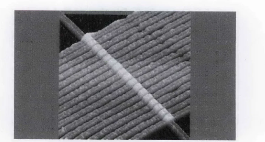
More on technology and dimensions [8]:
... an atomic force microscope image of a simple circuit with 17 memristors lined up in a row [see Figure 7]. Each memristor has a bottom wire that contacts one side of the device and a top wire that contacts the oppo-site side. The wires in this image are 50 nm wide, or about 150 atoms in total width.
7. Readers' Feedback to Scientists
Creating the First Memristor [8]
Among many reader comments, some are listed below that provide insight, or show misunderstanding, or are open to debate.7.1 Objections to Qualifying the
Memristor as the Four Basic Element
We have voltage-variable capacitors and voltage-vari-able resistors, both of which make my linear circuits behave horribly. Take a piece of iron, it has memory of a magnetic field, we called it core memory back, in the dark ages. Now we have a charge-variable resistor. Way cool, but a 4th basic component? If its properties are the basis of defining a new component, then the previously mentioned ones also qualify, making it much higher in number than 4th.
As an academic electrotechnical engineer, I have to object to calling this a "fourth basic element." There is no "gap" for this component to fill. There only exist three -basic- components, i.e. ones that rely on funda-mental physical principles, and that have parallels in other fields of science (like capacitor/spring and induc-tor/mass).
I congratulate the researchers on creating an (apparent) efficient implementation of a device that may be used extensively in analog or digital circuits; however, they have no ground for calling it a fourth elementary com-ponent.
I too question the concept of a fundamental "missing fourth element." The fundamental Maxwellian relation-ships between electron potential (voltage) and flux (cur-rent) are defined by the proportional, integral and
dif-220
Figure 7. An atomic-force microscope image of a simple circuit (image courtesy of J. J. Yang, HP Labs).
ferential. functions, viz, voltage proportional to current (resistor); voltage proportional to the integral of current (capacitor) and voltage proportional to the derivative of current (inductor). Together these can be used to define an arbitrary linear circuit behavior using a system of second-order differential equations. There is no need for a fourth (or fifth or sixth ... ) fundamental element unless you need to describe a third- (or fourth- or fifth-) order differential system - in which case the additional
ele-ments would need to exhibit second (or higher) order derivative or integral behavior. The memristor does none of these things - it is a nonlinear component (like
many others) whose fundamental behavior cannot be described by a linear system of equations.
These comments are partly correct, as a memristor can be built with a mutator (a linear two-port) terminated with a resistor. So, why call it the fourth basic element? Several replies are in order:
* By the same token, an inductor (capacitor) can be built with a gyrator (also a mutator) terminated in a capacitor (inductor).
* Restricted to the linear world, one can not distinguish a memristor from a resistor, and a combination of passive nonlinear resistors, capacitors, and inductors can realize a memristor.
* Memristive systems exist as shown with examples in Section 5.
* Is a memristor needed? Yes, as a building block for modeling, and possibly for realizing complex phenom-ena, at least with simpler topologies, if it can be built simply and cheaply, which is what took place with its nanoscale realization.
7.2 Comparison with Digital Devices
Everything ascribed to this device can be done to what-ever accuracy desired by a standard digital computer; and it can be done today.I think you missed the train back in the '70s. Analog died a long time ago and analog computers are a com-IEEE Antennas and Propagation Magazine, Vol. 50, No. 5, October 2008
plete joke. (too much development time and not as ver-satile as digital). This tech should help with the devel-opment of static RAM that holds its value even when no voltage is applied .... When reading the voltage from the resistor, does it discharge like a capacitor does? I find it hard to believe that some device will continue to hold an electric potential when being scanned/observed and not revert back to some voltage-neutral state. Maybe I've played in the transistor world too long. And FYI, the original poster failed to list the semiconductor in his list of electronic circuit elements.
Digital is dead. The Future(TM) is Analog.
Yes, can be done with a digital computer if one has enough time and spends considerable programming effort. The meniristor's memory lies in the value of the resistor, and not in the voltage across it. I tend to agree with analog being the future, as it is much faster, and digital exists because of our inability to store and oper-ate on anything other than binary.
7.3 And the Winners Are...
Great, so that digital logic final I just took is already out of date.My CD player will remember perfectly what I played the last Saturday, but with no disc inside. Great.
8. Conclusions
Several aspects of models and modeling, ranging from their usage to their postulation, have been discussed. The case of "an exploratory fourth basic element," namely the meniristor, which is becoming a reality as a nano-device and opening new visions and
paradigms, has been presented. The messages of this tutorial are many-fold:
* The proper model has to be chosen for the problem at hand. More complex models than necessary cause a waste of resources and obscure insight. For a simple logic analysis of a CMOS circuit, there is no need to use a complicated BSIM model.
* One should be very careful when using models, be it for analysis and/or design. The right model should be used correctly. Improper descriptions may lead to erroneous designs or faulty conclusions.
* Efforts spent in developing new ideas, postulating new elements, creating new paradigms have once more
proven to be fruitful. Mendeleev's periodic table has already been mentioned. another very good example is George Boole's Boolean Algebra, which has laid out the mathematical basis of today's computers almost a century after its creation, and now memristors, a little less than half a century later.
* Similar to the "chicken and egg" dilemma, the modem debate is "Which comes first: science or technology?" No matter what the answer is, it is certain that they keep influencing each other in a positive manner, and hope-fully for the benefit of society.
* With their IC realization and expectations thereof, it is certain that much will be read of and heard of concern-ing memristors and memristive systems. It is hoped that this tutorial will be of some help in understanding them.
9. References
I. Sedra/Smith, Microelectronic Circuits, Fifth Edition, Oxford,
Oxford University Press, 2003.
2. Leon 0. Chua, "Memaristor -The Missing Circuit Element,"
IEEE Transactions on Circuit Theory, 18, 5, September 1971, pp.
507- 519.
3. Leon 0. Chua and Sung Mo Kang, "Memristive Devices and Systems," IEEE Transactions on Circuit Theory. 64, 2, February 1976, pp. 209- 222.
4. Leon 0. Chua and Chong-Wei Tseng, "A Memristive Circuit Model for P-N Junction Diodes," International Journal of Circuit Theory and Applications, 2, 4, May 1974, pp. 367-3 89.
5. Jamie Beckett, "Demystifying the Memristor: Proof of Fourth
Basic Circuit Element Could Transform Computing," April 2008, http://www.hpl.hp.com/news/2008/apr-jun/menuilstor.html.
6. R. Stanley Williams, "HP Memristor FAQ," http://www.hpl.hp.com/news/2008/apr-un/m~enuifstor _faq.htmnl. 7. Dmitri B. Strukov, Gregory S. Snider, Duncan R. Stewart, and R. Stanley Williams, "The Missing Memristor Found," Nature
International Weekly Journal of Science, No. 453, May 1, 2008,
pp. 80-83; http://www.nature.com/nature/J~ourmal/v45 3/n7l 191/-full] nature06932.html#B2 1.
8. Bryan Gardiner, "Scientists Create First Memristor: Missing Fourth Electronic Circuit Element," April 30, 2008, http://blog.wired.com/lgadgets/2008/04/scientists-prov.htmll. (4'l