ARCHITECTURAL VIEWPOINTS FOR
GLOBAL SOFTWARE DEVELOPMENT
A THESIS
SUBMITTED TO THE DEPARTMENT OF COMPUTER ENGINEERING AND THE GRADUATE SCHOOL OF ENGINEERING AND SCIENCE
OF BİLKENT UNIVERSITY
IN PARTIAL FULLFILMENT OF THE REQUIREMENTS FOR THE DEGREE OF
MASTER OF SCIENCE
By
Buğra Mehmet Yıldız
August 2011
i
I certify that I have read this thesis and that in my opinion it is fully adequate, in scope and in quality, as a thesis for the degree of Master of Science.
Asst. Prof. Dr. Bedir Tekinerdoğan (Supervisor)
I certify that I have read this thesis and that in my opinion it is fully adequate, in scope and in quality, as a thesis for the degree of Master of Science.
Asst. Prof. Dr. Uluç Saranlı
I certify that I have read this thesis and that in my opinion it is fully adequate, in scope and in quality, as a thesis for the degree of Master of Science.
Asst. Prof. Dr. Pınar Şenkul
Approved for the Graduate School of Engineering and Science:
Prof. Dr. Levent Onural
ii
ABSTRACT
ARCHITECTURAL VIEWPOINTS FOR GLOBAL
SOFTWARE DEVELOPMENT
Buğra Mehmet Yıldız M.S. in Computer Engineering
Supervisor: Asst. Prof. Dr. Bedir Tekinerdoğan August 2011
Current trends in software engineering show that large software projects have to operate with teams that are working in different locations. The reason behind this globalization of software development stems from clear business goals such as reducing cost of development, solving local IT skills shortage, and supporting outsourcing and offshoring. There is ample reason that these factors will be even stronger in the future, and as such we will face a further globalization of software development. To cope with these problems, the concept of Global Software Development (GSD) is introduced. GSD is a relatively new concept in software development that can be considered as the coordinated activity of software development that is not localized and central but geographically distributed.
Designing a proper architecture of GSD is important to meet the requirements for the communication, coordination and control of distributed GSD teams. However, an analysis of the literature on GSD shows that research in this area has been generally focused on social issues focusing on some concerns such as intercultural communication problems and coordination. It is generally accepted that software architecture design plays a fundamental role in coping with the inherent difficulties of the development of large-scale and complex software. Unfortunately, in both GSD and software architecture design communities, the architecture design of GSD systems has not been explicitly addressed.
iii
This study aims to provide a contribution in this context by explicitly focusing on the architecture design of GSD. A common practice is to model and document different architectural views for describing the architecture according to the stakeholders’ concerns. Having multiple views helps to separate the concerns and as such support the modeling, understanding, communication and analysis of the software architecture for different stakeholders. Architectural views conform to viewpoints that represent the conventions for constructing and using a view. In this study, we propose seven architectural viewpoints which have been specifically defined for modeling GSD architecture. To define architecture viewpoints, we first describe a general GSD model. The meta-model has been derived after a thorough analysis of the related GSD literature. The meta-model consists of six different parts which form the abstract syntax of the architectural viewpoints. After the meta-model derivation, we also suggest textual and visual concrete syntaxes for the meta-model in order to complete viewpoint definition.
Supporting the architect in deriving architectural views based on the corresponding architectural viewpoints, we present a question framework. The question framework consists of six sets of questions related to the key concerns of a GSD project. Based on the answers given to the questions in this framework, the GSD application architecture can be derived by applying predefined design actions in the question framework. We have developed the tool called Global Architect which implements the question framework. Global Architect takes as input the answers to the provided questions and subsequently generates the textual architecture description of the required viewpoint. On its turn, the textual description is used to generate the visual presentation of the application architecture for the GSD project.
Keywords: Global Software Development, Architecture Modeling, Architectural
iv
ÖZET
KÜRESEL YAZILIM GELİŞTİRME İÇİN MİMARİ
BAKIŞ AÇILARI
Buğra Mehmet Yıldız
Bilgisayar Mühendisliği Bölümü Yüksek Lisans Tez Yöneticisi: Y. Doç. Dr. Bedir Tekinerdoğan
Ağustos 2011
Yazılım geliştirme yaklaşımı, son yıllarda tek merkezli geliştirme yerine küresel olarak dağıtılmış geliştirmeye kaymaktadır. Küresel veya dağıtılmış olarak da adlandırılan bu tip geliştirmede, belli takımlar, coğrafi olarak dünyanın değişik yerlerine dağılmış olan değişik sitelerde çalışır. Bu takımlar yalnızca kodlama üzerine değil, aynı zamanda yazılım pazarlaması, bakım ve test gibi yazılımın diğer alanlarında da çalışmaktadır. Tüm geliştirme, değişik ülkelere dağılmış merkezleri olan bir şirket tarafından idare edilebileceği gibi iş yükü sözleşmeli alt yükleniciler ile de paylaşılabilir. Ticari kaygı gütmeyen açık kaynak geliştirme grupları ve organizasyonlar da Küresel Yazılım Geliştirme (KYG) takımları olarak sınıflandırılabilir.
Dağıtılmış KYG takımlarının iletişim, koordinasyon ve kontrol gereksinimlerini karşılamak için uygun bir KYG mimarisi geliştirmek önemlidir. Bununla birlikte, KYG literatür taraması gösteriyor ki bu alandaki araştırmalar daha çok kültürler arası iletişim ve koordinasyon problemleri gibi sosyal mevzulara yoğunlaşmıştır. Yazılım mimarisinin geniş çaplı ve karmaşık yazılımların geliştirilmesinde önemli bir rol oynadığı bilinen bir gerçektir. Fakat hem KYG hem de yazılım mimarisi toplulukları, KYG mimarisinin tasarımı konusunu açık olarak konu etmemişlerdir.
Bu anlamda, bu çalışma KYG mimarisinin tasarımını konu ederek bu alanda katkı sağlamayı amaçlamaktadır. Mimariyi paydaşların endişelerine göre betimlemek için değişik mimari bakışları modellemek ve dökümlemek genel bir
v
uygulamadır. Birden çok bakışın kullanılması, farklı paydaşlar için yazılım mimarisinin modellenmesi, anlaşılması, iletişimde kullanılması ve analiz edilmesine yardım etmektedir. Mimari bakışlar, bakışların nasıl inşa edilmesi ve kullanılması gerektiğini tanımlayan bakış açılarına uyarlar. Bu çalışmada, KYG mimarisinin modellenmesi için tanımlanmış olan yedi adet mimari bakış açısı sunuyoruz. Mimari bakış açılarının tanımlanması için, öncelikle genel bir KYG meta-modeli tanımladık. Meta-model ayrıntılı bir literatür araştırması sonucu oluşturuldu. Meta-model, mimari bakış açılarının soyut dilbilgisini oluşturan altı adet parçadan oluşuyor. Meta-modelin tanımlanmasından sonra, meta-model için yazılı ve görsel somut dilbilgisi de, bakış açısı tanımlamasını tamamlamak için önerildi.
Bakış açılarına dayanan mimari bakışların elde edilmesinde mimarı desteklemek amacıyla bir soru çatısı sunduk. Soru çatısı, bir KYG projesinin anahtar elementleriyle ilişkili altı adet soru kümesi içeriyor. Bu soru çatısındaki sorulara verilen yanıtlara dayanarak, çatıda önceden tanımlanmış olan tasarım hareketlerinin uygulanmasıyla KYG mimarisi elde edilebilir. Bu soru çatısını
Global Architect (Küresel Mimar) adını verdiğimiz bir araç geliştirerek
uyguladık. Küresel Mimar sorulara verilen yanıtları alarak yazılı biçimdeki mimari tanımlamayı oluşturuyor. Daha sonra, bu yazılı tanımlama kullanılarak KYG projesinin görsel biçimde olan uygulama mimarisi çıkartılıyor.
Anahtar Sözcükler: Küresel Yazılım Geliştirme, Mimari Modelleme, Mimari
vi
Acknowledgements
It was a great honor for me to work with my supervisor Asst. Prof. Dr. Bedir Tekinerdoğan, who has supported me all the time during my master study. He encouraged me and showed guidance with his sound suggestions and criticisms. His enthusiastic approach towards software engineering made me also excited about studying on this interesting and challenging area.
I would also like to specially thank to Asst. Prof. Dr Pınar Şenkul and Asst. Prof. Dr. Uluç Saranlı for their valuable comments on my thesis.
Members of EA128, Ateş, Damla, Hande and Selen deserve much appreciation for their valuable friendship whole the time we spent together. I must state my special thanks to Saadet for her continuous support.
Finally, I would like to express that this thesis would not have been possible unless my family, my mother Zehra, my father Necati and my younger brother Mert who showed their endless and unconditional love to me. It is my greatest chance in this world to be a part of this great family.
vii
Contents
1. INTRODUCTION ... 1 1.2PROBLEM STATEMENT... 2 1.3CONTRIBUTION... 3 1.4OUTLINE OF THESIS... 42. GLOBAL SOFTWARE DEVELOPMENT ... 6
2.1SINGLE SITE DEVELOPMENT... 6
2.2WHAT IS GLOBAL SOFTWARE DEVELOPMENT? ... 8
2.3EXPECTED BENEFITS OF GLOBAL SOFTWARE DEVELOPMENT... 10
2.4CHALLENGES OF GLOBAL SOFTWARE DEVELOPMENT... 12
3. ARCHITECTURAL VIEWPOINTS AND SOFTWARE LANGUAGE ENRINEERING ... 15
3.1SOFTWARE ARCHITECTURAL VIEWPOINTS... 15
3.1.1 Definitions ... 16
3.1.2 Current Architectural Frameworks ... 17
3.2ARCHITECTURAL VIEWPOINTS AS DSLS... 19
4. META-MODEL FOR GLOBAL SOFTWARE DEVELOPMENT... 21
4.1DEPLOYMENT UNIT... 21 4.2PROCESS UNIT... 23 4.3DATA UNIT... 24 4.4COMMUNICATION UNIT... 26 4.5TOOL UNIT... 27 4.6MIGRATION UNIT... 28
5. ARCHITECTURAL VIEWPOINTS FOR GLOBAL SOFTWARE DEVELOPMENT... 29
5.1VIEWPOINT DEFINITION GUIDELINE... 29
5.2DEPLOYMENT VIEWPOINT... 31
viii 5.4COORDINATION VIEWPOINT... 35 5.5DATA VIEWPOINT... 36 5.6COMMUNICATION VIEWPOINT... 38 5.7TOOL VIEWPOINT... 40 5.8MIGRATION VIEWPOINT... 42
6. DERIVING APPLICATION ARCHITECTURE USING QUESTION FRAMEWORK ... 45
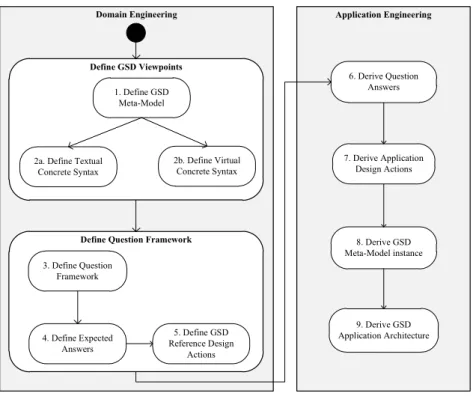
6.1ADOPTED APPROACH FOR DERIVING APPLICATION ARCHITECTURE... 45
6.2OVERVIEW OF THE QUESTION FRAMEWORK... 47
6.3DEPLOYMENT QUESTION SET... 49 6.4PROCESS QUESTION SET... 50 6.5DATA QUESTION SET... 52 6.6COMMUNICATION QUESTION SET... 54 6.7TOOL QUESTION SET... 56 6.8MIGRATION QUESTION SET... 57
7. TOOL SUPPORT FOR GENERATING APPLICATION ARCHITECTURE .... 59
7.1OVERVIEW OF TOOL SUPPORT... 59
7.2GLOBAL ARCHITECT... 61
7.3XTEXT... 63
7.3.1 Global Software Deployment Modeling Language (GSDML)... 64
7.3.2 Global Software Process Modeling Language (GSPML)... 66
7.3.3 Global Software Coordination Modeling Language (GSCOML)... 67
7.3.4 Global Software Data Modeling Language (GSDAML) ... 69
7.3.5 Global Software Communication Modeling Language (GSCML)... 70
7.3.6 Global Software Tool Modeling Language (GSTML) ... 72
7.3.7 Global Software Migration Modeling Language (GSMML) ... 74
7.4USING GRAPHICAL MODELING FRAMEWORK TO DEFINE VISUAL REPRESENTATIONS... 76
8. RELATED WORK... 81
ix
List of Figures
Figure 2.1 Conceptual Architecture of Single Site Software Development... 7
Figure 2.2 Conceptual Architecture of Global Software Development ... 10
Figure 3.1 Conceptual Model for Architectural Concepts based on [31]... 17
Figure 4.1 Deployment Meta-Model Unit... 22
Figure 4.2 Process Meta-Model Unit ... 23
Figure 4.3 Data Meta-Model Unit ... 25
Figure 4.4 Communication Meta-Model Unit... 26
Figure 4.5 Tool Meta-Model Unit ... 28
Figure 4.6 Migration Meta-Model Unit ... 28
Figure 5.1 Deployment View: Example Case ... 32
Figure 5.2 Process View: Example Case... 34
Figure 5.3 Coordination View: Example Case... 36
Figure 5.4 Data View: Example Case ... 38
Figure 5.5 Communication View: Example Case ... 40
Figure 5.6 Tool View: Example Case ... 42
Figure 5.7 Migration View: Example Case... 44
Figure 6.1 Adopted Approach for Deriving Application Architecture ... 46
Figure 6.2 Question Framework Concepts Model ... 47
Figure 7.1 Tool Support Activities for Deriving Application Architecture ... 60
Figure 7.2 Screenshot from Global Architect ... 61
Figure 7.3 Global Software Deployment Modeling Language ... 64
Figure 7.4 GSDML: Example Case... 65
Figure 7.5 Global Software Process Modeling Language... 66
Figure 7.6 GSPML: Example Case ... 67
Figure 7.7 Global Software Coordination Modeling Language... 68
Figure 7.8 GSCOML: Example Case... 68
Figure 7.9 Global Software Data Modeling Language ... 69
Figure 7.10 GSDAML: Example Case... 70
Figure 7.11 Global Software Communication Modeling Language ... 71
Figure 7.12 GSCML: Example Case... 72
Figure 7.13 Global Software Tool Modeling Language ... 73
Figure 7.14 GSTML: Example Case ... 74
Figure 7.15 Global Software Migration Modeling Language ... 75
Figure 7.16 GSMML: Example Case... 76
Figure 7.17 Annotated Textual ECore Model of Migration Viewpoint... 78
x
List of Tables
Table 2.1 Software Engineer Salaries of Some GSD Participant Countries [16]
... 11
Table 5.1 Viewpoint Guide Template For GSD... 30
Table 5.2 Deployment Viewpoint ... 31
Table 5.3 Process Viewpoint... 33
Table 5.4 Coordination Viewpoint ... 35
Table 5.5 Data Viewpoint ... 37
Table 5.6 Communication Viewpoint ... 39
Table 5.7 Tool Viewpoint ... 41
Table 5.8 Migration Viewpoint ... 43
Table 6.1 Deployment Question Set... 50
Table 6.2 Process Question Set ... 52
Table 6.3 Data Question Set... 54
Table 6.4 Communication Question Set... 55
Table 6.5 Tool Question Set... 57
1
Chapter 1
Introduction
Current trends in software engineering show that large software projects have to operate with teams that are working in different locations. The reason behind this globalization of software development stems from clear business goals such as reducing cost of development, solving local IT skills shortage, and supporting outsourcing and offshoring [21]. There is ample reason that these factors will be even stronger in the future, and as such we will face a further globalization of software development [12]. To cope with these problems, the concept of global software development (GSD) is introduced. GSD is a relatively new concept in software development that can be considered as the coordinated activity of software development that is not localized and central but geographically distributed. Typically, GSD teams work on different areas of software business, such as business/marketing, maintenance, testing as well as on software implementation. The development activities may be managed by just one company that is distributed to many centers in different countries or many companies can work on specific projects as organizers and subcontractors for sharing work weight. Open source development groups and organizations that usually do not drive any commercial benefit can also be classified as Global Software Development (GSD) teams [51].
2
1.2 Problem Statement
A GSD architecture usually consists of several nodes, or sites, on which different teams are working to develop a part of the system. The teams could include development teams, testing teams, management teams, etc. Usually each site will also be responsible for following a particular process. In addition, each site might have its own local data storage.
Overall we can identify three important key concerns in designing GSD:
Communication: Communication mechanisms within and across sites. Typically
the different sites need to adopt a common communication protocol.
Coordination: Coordination of the activities within and across sites to develop
the software according to the requirements. Coordination will be necessary to align the workflows and schedules of the different sites. An important goal could be to optimize the development using appropriate coordination mechanisms.
Control: Systematic control mechanisms for analyzing, monitoring and guiding
the development activities. This does not only include controlling whether the functional requirements are performed but also which and to what extent quality requirements are addressed.
In fact each of these concerns requires further in-depth investigation and has also been broadly discussed in the GSD community. The important issue that we would like to address is that each of these concerns and the way they are allocated in the GSD environment will have a direct impact on the GSD architecture. Likewise, designing a proper architecture for GSD is important to satisfy the requirements for the communication, coordination and control of distributed GSD teams.
3
It is generally accepted that software architecture design plays a fundamental role in coping with the inherent difficulties of the development of large-scale and complex software. Research on architecture design in the last two decades has resulted in different useful techniques and approaches. Different architectural modeling approaches for representing multiple views of the architecture have been proposed. Yet, designing robust software architectures remains difficult due to the various concerns, and the higher abstraction level. In the software architecture design community the endeavor of software architecting seems to have been mainly focused on architecting in single systems. However, current trends in software engineering show that large software projects have to operate with teams that are working in different locations.
On the other hand, the global software development community seems to have largely discussed non technical issues such as intercultural communication problems and coordination. Unfortunately, less focus has been given from a technical architecting perspective.
1.3 Contribution
This thesis aims to address problems defined in the previous section by explicitly focusing on the software architecture design of GSD. The contribution of this thesis can be summarized as follows:
Meta-model for GSD: For the derivation of the application architecture, we have
defined a general GSD meta-model which contains the key concepts of distributed development. The meta-model has been derived after a thorough analysis of the related GSD architecture. The meta-model consists of six different parts which form the abstract syntax of the architectural viewpoints.
4
Viewpoints for GSD: Based on the defined meta-model, we have described
seven architectural viewpoints which have been specifically defined for modeling GSD application architecture. These seven viewpoints help to separate the GSD concerns and as such support the modeling, understanding, communication and analysis of the GSD architecture.
Domain-Specific Language for GSD Application Architecture: Each viewpoint
for GSD application architecture includes textual concrete syntax definition which forms domain-specific languages for GSD application architecture. To the best of our knowledge, these are the first DSLs on GSD in the literature.
Question Framework: For helping the architect to derive GSD architecture using
viewpoints, we present a question framework. The question framework targets the key concerns of a GSD project. It consists of six question sets each of which has around twenty questions. Each question has an expected answer as defined in the literature. Based on the answers given to the questions in this framework, the GSD application architecture of the particular architectural viewpoint can be derived.
Tool Support: We have developed the tool Global Architect that implements the
question framework. Global Architect takes as input the answers to the questions and generates the corresponding textual architecture for the required viewpoint. The textual description of the architecture is mapped to the visual presentation of the application architecture of GSD project using XText and Eclipse Graphical Modeling Framework.
1.4 Outline of Thesis
The thesis is organized as follows: Chapter 2 provides a background of Global Software Development and explains the benefits and problems of GSD approach. Chapter 3 presents the concepts related to software language engineering, architectural viewpoints and frameworks. Further it represents the
5
adopted approach that we have followed for the derivation of application architecture. In Chapter 4, we present the meta-model of Global Software Development. Chapter 5 describes seven viewpoints together with visual concrete syntaxes. The question Framework is given in Chapter 6. Chapter 7 presents the tool support given for the adopted approach. Chapter 8 provides the related work and finally Chapter 9 concludes the thesis.
6
Chapter 2
Global Software Development
This chapter provides background information on Global Software Development paradigm. Section 2.1 describes the traditional single site development. Section 2.2 provides the introduction to Global Software Development. Section 2.3 describes the expected benefits from the GSD approach. Finally, the challenges of GSD are presented in Section 2.4.
2.1 Single Site Development
Single site development can be qualified as the traditional way of software development that is still followed by local-based software companies. In this kind of development, one or more development teams of a company are located in one location such as company building. The team or people responsible for customer relations sometimes travel to customer sites in need of communication with customer. The conceptual model of single site development is shown in Figure 2.1.
7
Figure 2.1 Conceptual Architecture of Single Site Software Development
There are some problems faced by the companies that apply single site development approach. Based on the literature study we could derive the following issues:
Long Project Periods: In single site development, teams usually start working at
7-9 am and continue working until 6-7 pm in the local time of the located site. This corresponds to about 8-9 hours of working per day and about 45 hours of working in a week. With this working schedule, the projects last several months or even several years depending on the project sizes.
High Production Cost in Developed Countries: Teams are located constantly in
a particular city in single site development. This situation leads to a fixed amount of living expenses for the people working for the company since food and housing costs do not much differ in city base. The average living expenses in a city affect the cost of the developed software: If the city’s food and/or housing prices are high like Tokyo, Moscow, Geneva, Zurich or New York [14], the expected cost of the software would be high if the single site development approach is followed. On the other hand, as it can be expected, the second and third world countries offer cheaper living that would lead to cheaper software
8
development cost (Note that, we compare cost of living versus cost of developed software here; the quality is not mentioned here, one may expect better products in developed countries whose living cost is higher).
Limited Market: Single site development limits the target market of the
company. The company generally serves to the customers from the same city or from the cities in the same country because of high travel and communication costs to other countries. The companies that apply single site development approach rarely find customers from other countries that stop these companies to take a pay from offshore markets. So, the company cannot get into a competition with other companies in different markets.
Lack of Expertise: Another limitation is that sometimes, single site development
suffers from lack of expertise. This is because the single site development approach depends on the local skill pool. If a company needs an expert from a particular area, it has to find a person located near to the company’s location. If there is a lack of expertise in the available skill pool, the company may choose to train its own workers or hire/employ a person from other locations or abroad where both approaches are costly compared to the local solution.
Governmental Obligations: A company who works in single site should obey
the regulations and laws put by the government of that country. Sometimes these regulations can put boundaries to software development area or to market competitions and the company cannot escape from these regulations unless the company has other branches in other countries.
2.2 What is Global Software Development?
With the act of globalization, the companies working in many different areas have moved their production centers to other countries for getting a higher share from the world pie especially in the last two decades. The software industry is
9
also affected with world globalization trend. In order to solve the problems of single site development that we stated in the previous section and get advantage of outsourcing (hiring a subcontractor in order to do some function) and offshoring (locating some functions to be done in another country), many software companies have carried their development sites to other countries such as India and China.
In this so-called global or distributed [11] software development, there are a number of teams working on different sites that are distributed geographically across the world. These teams work not only coding but also focus on different software development jobs such as business/marketing, maintenance, testing. Development of a project may be managed by just one company whose centers are distributed to different countries or subcontractors around the world can share work weight of organizer companies. Not only private commercial companies but also open source development groups and organizations that usually do not drive any commercial benefit can be also classified as Global Software Development (GSD) teams. Conceptual architecture of GSD is given in Figure 2.2.
10
Figure 2.2 Conceptual Architecture of Global Software Development
2.3 Expected Benefits of Global Software
Development
The main purpose of applying Global Software Development approach for a company is to gain more profit from the development. To reach this target, GSD offers the following advantages:
Cheaper Production: Decreasing the cost of the production is generally
considered as one of the main motivations for adopting GSD. One of the main factors for the cost of production is the wages of the engineers in the project. By moving the production centers to the countries in which is cheaper than the company’s home country that the cost for wages and likewise cost of production can be substantially decreased [15]. To show the wage difference between the GSD participant countries, Table 2.1 shows lower bound yearly incomes of software engineers in different countries [16]. The reason why most of the
11
American outsourcing is done to India, the country with the lowest average minimum salary is clear from this table.
Country Minimum Yearly Salary($)
United States 42,757 India 6,784 China 10,180 Ireland 50,588 Russia 12,825 Singapore 15,534 New Zealand 33,566 Australia 41,961 Germany 32,002 Netherlands 35,247 England 37,669 Brazil 15,428 Turkey 20,793
Table 2.1 Software Engineer Salaries of Some GSD Participant Countries [16]
Large Pool of Skilled Labor: In single site development, a company depends on
the local skill pool. On the contrary, globally distributed companies can reach to different countries’ man power. When an expertise is needed on some subject, it is often easier to solve this by using globally distributed centers rather than one center located at one country [17] [18].
Faster Time to Market: One of the main advantages of GSD is that it supports
“Follow-the-sun” approach [19]. As it can be understood from its name, the daily development time may increase from 8-9 hours up to 24 hours. This approach takes the advantage of the sun’s daily action on earth and so different time zones. As one center finishes its daily shift, the other center in another place in the world can just start its daily shift and so 24 hours of the day is used for development.
New Markets: By allocating different centers in different countries, a company
catches the chance of joining the local markets. So, the company can reach more customers. In [20], it is stated that new job opportunities created locally can lead to find more customers in that local area.
12
Other advantages: Other than these commonly accepted benefits of GSD, the
study in [21] reports some unknown benefits of GSD. This study reports additional benefits under organizational, team and process/task categories. From organizational perspective, since a company can reach to a large pool of skilled labor, the company’s innovation ability and resource allocation improves. From teams perspective, task modularization improves because tasks are tend to be assigned in a way that interdependencies are kept low and so the coordination cost decreases. GSD requires keeping track of the information flow so more formal and explicit processes are defined and documentations and communication histories are recorded.
2.4 Challenges of Global Software Development
Although Global Software Development has several clear benefits for a company, it also has to face important challenges. In this context, we do not mean problems that are also common to single system development but indicate problems specific to Global Software Development settings where several teams located in different parts of the world. The following challenges have been identified in the GSD literature:Synchronous communication: From the nature of the distributed environment,
communication between sites becomes a vital activity for developers. But, at the same time difficulties exist in side-to-side communications. One of the difficulties is about synchronous communication. Each site has its own local time zone and because of the time zone differences, it becomes hard to find overlapping hours in the shifts. In [22], it is stated that finding common times for collaboration can cause delays in feedback.
Informal communication: Another problem is about informal communication
13
calls made in case of information needs or chats done during breaks. In unstable environments and projects that are open to changes, informal communication is especially important [23] [24]. But because of the distance, informal communication sometimes becomes harder or even impossible. The lack of informal communication leads to several negative situations such as absence of trust [25] [26] and to lose team spirit. This creates an obstacle in front of information sharing and communication tendency.
Teams’ background: Teams in different sites come from different cultures: both
social and work culture. Most of the time, they haven’t worked together before, they come from different trainings, and they don’t know about each others’ habits and thoughts. As social culture impact, one’s action can be felt as rude by the opposite site. For teams that are located in separate countries, language appears as a disadvantage sometimes. So, background difference can cause misunderstandings and misinterpretations which stops successful information exchange.
Awareness: Because of these communication problems, and since teams at
separate sites share little content in common, they usually don’t know what the people in the other sites are doing. This lack of awareness of other sites’ activities may introduce delays and unnecessary reworks.
Interdependencies between sites: As a general practice, task allocation is done in
a way that interdependencies between sites are as small as possible so that coordination and communication problems are reduced. Task allocation based on software architecture creates a challenge for software engineers to derive a suitable architecture and work division for multi-site development. Not only software architecture, but also dependencies based on other project artifacts such as detailed design, code, test and process documents causes more sites to collaborate. But it is not possible to do this ideally where no intersection work
14
exists. So, more coordination and communication mechanisms are needed to get rid of extra delays [27].
Interoperability: GSD sites often differ in terms of work culture so they use
different tools and development platforms. When activities that need collaboration of sites are done, interoperability becomes a barrier if sites don’t use similar platforms or tools.
Architectural Design: All the above challenges have been somehow discussed
in the GSD literature. Unfortunately, as stated before, the notion of architecture design has not yet been explicitly addressed. This includes architecture design, the modeling and documentation of the architecture, architecture analysis and architecture realization. In this thesis, we mainly focus on architecture design and its documentation.
15
Chapter 3
Architectural Viewpoints and
Software Language Engineering
This chapter presents information about software architectural viewpoints and our approach for deriving application architecture. Section 3.1 gives some background on software architectural viewpoints; it starts with definition subsection and ends with some example architectural frameworks from the literature. Section 3.2 expresses architectural viewpoints from domain-specific language perspective. The chapter ends with adopted approach for deriving application architecture of Global Software Development.
3.1 Software Architectural Viewpoints
A stakeholder can be defined as a person or a group of people who have some interest in the target system. Each stakeholder has some interest, expectations or concerns regarding to the system and the architect needs to satisfy the concerns of stakeholders. In order to satisfy the stakeholder concerns, looking at the system from just one perspective is not suitable. So, a common practice is to model and document the architecture from different viewpoints targeting
16
different stakeholders [1] [28] [29] [30]. General concepts regarding to architectural viewpoints are explained in the following subsection.
3.1.1 Definitions
IEEE provides the fundamental definitions related to software-intensive systems in IEEE 1471 standard [31]. In this standard, the following definitions are given:
System: A collection of components organized to accomplish a specific function
or set of functions.
System Stakeholder: An individual, team, or organization (or classes thereof)
with interests in, or concerns relative to, a system.
Architecture: The fundamental organization of a system embodied in its
components, their relationships to each other, and to the environment, and the principles guiding its design and evolution.
Architectural Description: A collection of products to document architecture.
View: A representation of a whole system from the perspective of a related set of
concerns.
Viewpoint: A specification of the conventions for constructing and using a view.
A pattern or template from which to develop individual views by establishing the purposes and audience for a view and the techniques for its creation and analysis.
Moving from these definitions, the conceptual model given in Figure 3.1 can be derived.
17 Architecture System Stakeholder Architectural Description View Viewpoint Concern has an described by organized by conforms to has used to capture identifies addresses Fi gure 3.1 Conceptual Model for Architectural Concepts based on [31]
Every system has an architecture. Architecture of a system is described in architectural description. Architectural description consists of several views each of which conforms to a viewpoint. Each viewpoint is defined in order to capture the concerns of stakeholders so addresses different stakeholders.
3.1.2 Current Architectural Frameworks
Architectural frameworks organizes architectural viewpoints and so allow architect to use these viewpoints in a consistent and correct manner. There are different architectural frameworks proposed in the literature both for software intensive and purpose specific use. Some important example architectural frameworks are discussed below.
In the Views and Beyond Approach [1], the authors introduce the notion of architectural styles as specialization of elements and their relations together with usage constraints. Architectural styles are often recurring forms that are used to present different aspects of a software system. The book represents several styles and these styles are grouped under three categories: Module,
Component-18
and-Connector and Allocation. Module styles are used to show basic units of implementations. Component-and-Connector styles organize system units during execution time. Allocation styles connect software and non-software system units. The application of a style results in a view of the system.
Kruchten’s 4+1 Architectural View Model [29] collects the views of the software intensive systems into four views: logical, development, process and physical. End user functionality is focused by logical view. The development view reflects the system from implementation point of view; this view is especially used by software developers. The process view represents dynamic perspective of a system. The physical view concentrates on how the software elements are mapped to non-software units. As the plus one, use cases and scenarios are used for satisfying end user interest.
Siemens’s Four View Model [28], consists of the following four viewpoints: conceptual, module, code and execution viewpoint. The Four View Model is similar to the Kruchten’s 4+1 Architectural View Model. The conceptual view is mapped to the use case model, the module view and code view correspond to logical and development views respectively; the execution view which represents dynamic side of software systems is similar to process view in 4+1 Model.
In this thesis, we focused on the software architectural frameworks but representing the system from different perspectives approach is also applied to enterprise architectures. Some examples can be shown as The Open Group Architecture Framework (TOGAF) [36], Zachman’s Framework for Enterprise Architecture [37] and ISO (ISO/IEC 10746) Reference Model of Open Distributed Processing (RM-ODP) [35].
19
3.2 Architectural Viewpoints as DSLs
Models are different in nature and quality and different classifications of models have been provided in the literature. Mellor et al. [52] make a distinction between three kinds of models, depending on their level of precision. A model can be considered as a Sketch, as a Blueprint, or as an Executable. According to [52], an executable model is a model that has everything required to produce the desired functionality of a single domain. Executable models are more precise than sketches or blueprints, and can be interpreted by model compilers.
Demirli and Tekinerdogan [32] introduce an approach for defining architectural viewpoints as domain-specific languages. Most architectural viewpoints function as a way of communication between stakeholders as sketches or blueprints for the detailed design stage. The study notes that although recent viewpoints tend to be defined more precisely, still they lack of some precision. This lack of precision may lead to lower the quality of the architectural documentation. So, a software language engineering approach of defining viewpoints as domain-specific languages will enhance the formal precision of architectural viewpoint since it will allow architect to get advantage of DSLs such as defining executable, formal views.
Every DSL has a meta-model. Meta-models can be considered the languages for models. In both software language engineering [34] and model-driven development domains [33], a meta-model should have the following elements:
Abstract syntax: The descriptions of the concepts which forms the vocabulary of
the languages and how these concepts come together to create a valid model.
Concrete syntax: The adopted notation for representing the concepts of the
language. Basically, we can distinguish between visual concrete syntax and textual concrete syntax. The visual concrete syntax defines how the concepts in
20
the language should appear in the visual diagrams; textual concrete syntax allows the models to be defined in textual form.
Semantics: Describes meanings of the concepts and relations defined in abstract
syntax. Semantics can be described using natural languages.
Moving from these elements of meta-models, the viewpoints can be also considered as languages for defining views [32]. So, the viewpoints can be thought as DSLs. In this study, we evaluate viewpoints of GSD as the languages for defining GSD views. Chapter 4 gives the abstract syntax definitions and Chapter 5 presents the concrete syntax definitions of GSD architectural viewpoints.
21
Chapter 4
Meta-Model for Global Software
Development
Based on the literature of GSD, we have defined a meta-model for GSD that defines the concepts and their relations. The meta-model presented in this section primarily aims to serve as the abstract syntax of the GSD viewpoints. Other than this functionality, the meta-model can also be used for enhancing the understanding of GSD and can support the model transformation. The designer may choose to derive an application architecture by him/herself if s/he doesn’t want to use the automated process that we presented in the previous section by using the meta-model directly.
Since the meta-model is quite large, we decomposed it into six meta-model units. Each of these meta-model units includes semantically close entities and address different concerns. Each unit is mapped to corresponding architecture viewpoint. These units are Deployment, Process, Data, Communication, Tool and Migration. We explain each unit in the following sections.
22
Deployment Unit concerns the deployment of the teams to different sites. The
meta-model of this unit is shown in Figure 4.1.
Figure 4.1 Deployment Meta-Model Unit
Team is the primary essential entity in the meta-model and is defined as a
group of persons that work together to achieve a particular goal. A Team may be organized in a temporary way that it will be dismissed after its function is complete. Each Team has particular Expertise Areas. Team is allocated at a particular Site. Site maps to a country, city or a building where a Team works at. Location attribute determines where Site is placed in the world. Time zone shows the local time of Site. Teams may belong to different types of
Organizations, such as commercial organizations, subcontractors or
non-profitable organizations such as open source communities. Teams can be from different countries and depending on the society they are in, they may have different Social Cultures. Like Social Culture, Team’s background including work experience, the time that members work together, their habits are captured by Work Culture entity.
23
Expertise Area, Team and Site can be further decomposed into sub-parts. For
example, a Software Team may consist of sub-Teams each responsible for Design, Implementation, Testing and Integration.
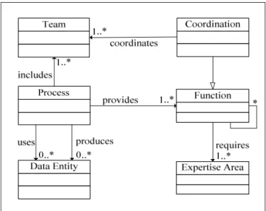
4.2 Process Unit
Process Unit concerns the different kind of processes in GSD. The meta-model
of this unit is shown in Figure 4.2.
Figure 4.2 Process Meta-Model Unit
Process is defined as a planned set of activities that aims to provide some
service. Teams participate in Process in order to provide some service. Service is defined with Function. A Function can be any service during software development process that requires some Expertise Areas such as software development, architecture design, business management, requirements elicitation and so on. Coordination is also a Function that should be provided for coordinating several Teams’ activities. A Process consumes or uses several different Data Entities and also creates other Data Entities for providing targeted Functions. For supporting activities defined in Process, Process
24
concept is further specialized into Workflow, Business Process and Development Process (not shown in figure).
Process is defined as a single entity in this meta-model unit. But in reality, Process is a complex entity which contains a complicated model of different
entities such as Roles, Activities, Checkpoints, etc. For the definition of Process itself as a meta-model, several process meta-model definitions are proposed for serving different purposes. Our meta-model can behave interoperable with these process meta-models through the entities such as Team, Data Entity, Expertise Area or Function that are presented in our meta-model. As an example of process meta-model definitions, Object Management Group’s (OMG) “Software & Systems Process Engineering Meta-Model Specification” (SPEM) [2] can be considered. Team and Data Entity elements of Process meta-model can be mapped to Role Use and Work Product Use elements in SPEM.
4.3 Data Unit
Data Unit is for representing ownership and physical deployment of software
25
Figure 4.3 Data Meta-Model Unit
Data Entity is the fundamental entity of this meta-model. It represents any
piece of data: digital, textual or informal piece of information such as notes taken by developers, telephone calls that are usually not recorded. Data Entity has size whose unit is defined by size type; for example, a 120-page report, 6 minutes of voice record, 2 gigabyte of digital data. Creation date and last update date show the history of Data Entity. Data Entity has Actual Format where it can be one of predefined formats (video, sound, text, picture and complex-Data Entity) or some designer defined format. If Data Entity is digital, then in addition to Actual Format, it has a Digital Format. Data Entity may be implemented in one or more Languages.
Data Entity is stored in Data Storage. Data Storage corresponds to any
object in real world that can store information. For example, some textual document is stored in paper form, or it is stored in a voice record, or it is stored digitally in the format of some text editor. Data Storage has ability to store some
Actual Formats and if it can store digital data, then it can support some Digital Formats also. A Data Storage instance is owned by one or more Teams and it
26
can be located in one Site or may be distributed over several Sites like distributed databases.
4.4 Communication Unit
Communication Unit focuses on the representation of both formal and informal
communication activities between Teams. The meta-model is shown in Figure 4.4.
Figure 4.4 Communication Meta-Model Unit
Communication is done over Communication Platform in the context of Process and it can be an instance of sudden/event based communication activity
like a telephone call or a continuous communication channel such as a discussion forum. Type attribute is for representing in which way
Communication takes place such as email, phone call, face-to-face chat and so
on. If Communication instance is not a channel, then it means it is sudden communication activity and so it has start and finish time attributes. Suggested time period is an important attribute for GSD since Teams work in different time zones, some Communication channels such as telephone channel can be used
27
effectively in a defined time period. For example, phone calls should be done during the hours when both sides are in or around their work hours.
Communication has two sides which are caller and receiver. Generally
speaking, caller starts communication and receiver is the one who is called by caller. For example, an email sender is classified as caller and receiver is the one who receives email. Sometimes, there can be multiple callers such as video conferences or there can be multiple receivers such as discussion forums. It is also possible that caller and receiver are the same such as a planned meeting. For all cases, caller and receivers are considered as Teams in this meta-model. While Teams communicate, one or more Data Entities are carried in the context of Communication. Speech in telephone calls, electronic mails’ body contents or attachments can be shown as examples of Data Entities carried by
Communication.
4.5 Tool Unit
Tool Unit captures details of tools used by Teams for communication and
28
Figure 4.5 Tool Meta-Model Unit
Tool is compatible with one or more Actual Format and Digital Format.
Platform is the set of Tools used by Teams for communication or providing some functions. Depending on the purpose, the platform is defined as Function
Platform or Communication Platform. Each Function is provided over a
particular Function Platform.
4.6 Migration Unit
Migration Unit concerns the migration and traveling of teams during GSD
activities. These travels are especially needed in the first and final phases of the projects to ease and support coordination and integration. The meta-model is shown in Figure 4.6.
Figure 4.6 Migration Meta-Model Unit
Migration is executed by one or more Teams from Site to Site at a particular date. In a Migration, Teams may carry Data Storage such as documents, digital data containers and so on. Migration is executed in the context of Process.
29
Chapter 5
Architectural Viewpoints for Global
Software Development
Based on the meta-model for GSD that we have defined in the previous chapter, in this chapter we will define the viewpoints for GSD. In Section 5.1, we present the Viewpoint Definition Guideline describing the template for viewpoint definitions. The subsequent sections define the Deployment, Process, Coordination, Data, Communication, Tool, Migration viewpoints. In each of these viewpoint sections, based on the corresponding abstract syntax as defined in the previous chapter, first viewpoint definition is given, followed by an example.
5.1 Viewpoint Definition Guideline
Defining a new architectural viewpoint implies writing a viewpoint guide. This is similar to the notion of style guide as defined in [1]. The viewpoint guide defines the vocabulary of the architectural element and relation types, and defines the rules for how that vocabulary can be used. For defining a viewpoint guide for a particular quality concern we apply the template as defined in Table 5.1.
30
Viewpoint Element Description
Name Unique name for the viewpoint
Element Types The architectural element types
native to the viewpoint
Relation Types The relation types among
architectural elements
Properties of Elements
Additional information on the element types
Topology Constraints
The rules of composition of the elements and relations.
Notation The adopted notation for the
element types and relation types. The notation can be textual or visual.
Relation to other views/viewpoints
The relation to other viewpoints other than the base viewpoint Table 5.1 Viewpoint Guide Template For GSD
A viewpoint defines the template for the views that can be instantiated from it. In that sense, we consider viewpoints as meta-models representing the basic concepts of the architecture from a particular perspective. To define viewpoints and likewise the viewpoint template, we believe it is necessary to define the corresponding meta-model. As we mentioned before given the key elements of a language, which are abstract syntax, concrete syntax and semantics, we can also evaluate viewpoints of Global Software Development as the languages for defining GSD views.
Likewise to define the viewpoints for GSD, we have to define the corresponding language including both the abstract syntax and the concrete syntax. The abstract syntax is defined based on the literature of GSD under the name of GSD meta-model in the previous chapter. Concrete syntax is included in the viewpoint guide of each viewpoint. In this study, we presented seven different parts each representing an architectural viewpoint for GSD systems. The viewpoints that we have defined based on the meta-model units in the previous section are Deployment, Process, Coordination, Data, Communication, Tool and Migration Viewpoints. These viewpoints are described in more detail in the following subsections.
31
5.2 Deployment Viewpoint
Deployment Viewpoint aims the representation of deployment of project teams
to different sites around the world. Guide for this viewpoint is given in Table 5.2.
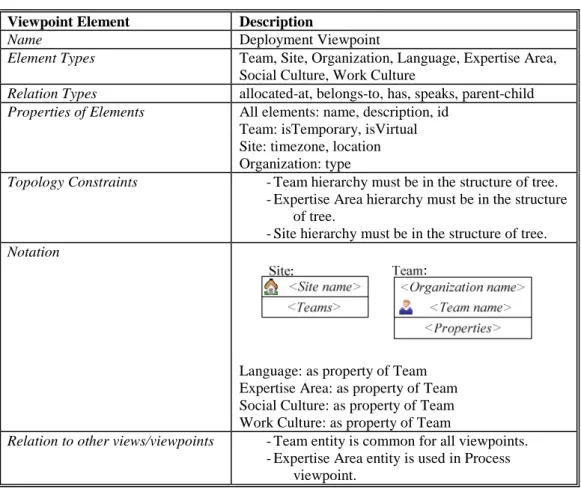
Viewpoint Element Description
Name Deployment Viewpoint
Element Types Team, Site, Organization, Language, Expertise Area,
Social Culture, Work Culture
Relation Types allocated-at, belongs-to, has, speaks, parent-child
Properties of Elements All elements: name, description, id
Team: isTemporary, isVirtual Site: timezone, location Organization: type
Topology Constraints -Team hierarchy must be in the structure of tree.
-Expertise Area hierarchy must be in the structure of tree.
-Site hierarchy must be in the structure of tree.
Notation
Language: as property of Team Expertise Area: as property of Team Social Culture: as property of Team Work Culture: as property of Team
Relation to other views/viewpoints -Team entity is common for all viewpoints.
-Expertise Area entity is used in Process viewpoint.
Table 5.2 Deployment Viewpoint
As an example case, consider a GSD project with 7 Sites located at different places in the world. Company A, the owner of the project, has its center operating in United States. Requirement Analysis is done in New York and Architecture Team works in Silicon Valley, California. Company A has development center in New Delhi, India where software development and test Teams work. Also, Company A works with a subcontractor company, Company B for some particular components. Company B’s center is located in Sao Paulo,
32
Brazil. Company B also has development and test Teams. Figure 5.1 shows the Deployment View of the case given in the description. The Deployment View is derived following the Deployment Viewpoint definition given previously.
Figure 5.1 Deployment View: Example Case
Team definition is the starting point of all viewpoints. The reason of this is that Team entity is included in all meta-model units. Since Team is a key entity, we use the teams defined in Deployment Viewpoint example as a base for the view definitions in the following viewpoint sections.
33
5.3 Process Viewpoint
Process Viewpoint aims the representation of the processes that are adopted by
different teams in the GSD project. The guide for this viewpoint is given in Table 5.3.
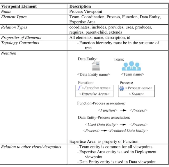
Viewpoint Element Description
Name Process Viewpoint
Element Types Team, Coordination, Process, Function, Data Entity,
Expertise Area
Relation Types coordinates, includes, provides, uses, produces,
requires, parent-child, extends
Properties of Elements All elements: name, description, id
Topology Constraints -Function hierarchy must be in the structure of
tree.
Notation
Expertise Area: as property of Function
Relation to other views/viewpoints -Team entity is common for all viewpoints.
-Expertise Area entity is used in Deployment viewpoint.
-Data Entity entity is used in Data viewpoint. Table 5.3 Process Viewpoint
Consider the following as an example case based on team definitions in the previous section’s example: Requirement Management Team follows a Requirement Analysis process which is done for serving Requirement Derivation function. The output of the Requirement Analysis process is Requirement Description Document. This document is used by Architecture
34
Team in order to design architecture. The document is an input to Architecture Design process and this process creates Architecture Description Document which then be used in implementation process. Since there are two Sites taking role in development, Architecture Description Document is an input to two different development processes whose outputs are working software units. This process flow is shown in Process View in Figure 5.2. The Process View is derived following the Process Viewpoint definition given before.
Figure 5.2 Process View: Example Case
For keeping the diagram simple, we didn’t include some other details of this process flow such as Detailed Design stage coming after Architecture Derivation before starting implementation or Testing of software units that are gotten at the end of Implementation processes.
35
5.4 Coordination Viewpoint
Coordination Viewpoint captures the coordination activities of project teams.
There is no separate meta-model unit for this viewpoint, but it uses Process meta-model unit as the abstract syntax. The viewpoint aims the representation of the coordinated and coordinator teams. The viewpoint guide is shown in Table 5.4.
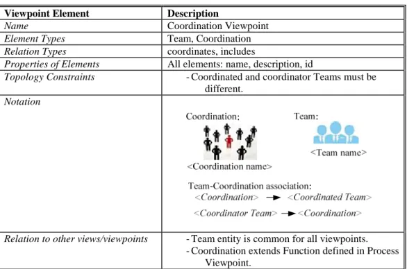
Viewpoint Element Description
Name Coordination Viewpoint
Element Types Team, Coordination
Relation Types coordinates, includes
Properties of Elements All elements: name, description, id
Topology Constraints -Coordinated and coordinator Teams must be
different.
Notation
Relation to other views/viewpoints -Team entity is common for all viewpoints.
-Coordination extends Function defined in Process Viewpoint.
Table 5.4 Coordination Viewpoint
Suppose that there are two coordination cases in the project defined in the previous examples. In the first coordination case, Requirement Management Team coordinates Architecture Team. This coordination occurs over the requirements of the project. The second coordination occurs between Architecture and Development Teams. Architecture Team coordinates Development Teams through some checkpoints. These two coordination instances are shown in Figure 5.3 that shows the Coordination view of the example project case.
36
Figure 5.3 Coordination View: Example Case
5.5 Data Viewpoint
Ownership and physical deployment of data in GSD projects are represented in
Data Viewpoint. This viewpoint’s guide is shown in Table 5.5.
Viewpoint Element Description
Name Data Viewpoint
Element Types Language, Team, Site, Data Storage, Digital Format,
Actual Format, Data Entity
Relation Types in, owned by, stored in, located by, can store
Properties of Elements All elements: name, description, id
Data Storage: canStoreDigital
Data Entity: size, isDigital, sizeType, creationDate, lastUpdateDate
Topology Constraints -Data Storage can store Digital Format only if
Data Storage can store digital.
-Data Entity is in some Digital Format only if Data Entity is digital.
37 Notation
Relation to other views/viewpoints -Team entity is common for all viewpoints.
-Data Entity entity is used Process and Communication viewpoints.
-Data Storage is used in Migration viewpoint. -Actual and Digital Formats are used in Tool
Viewpoint. Table 5.5 Data Viewpoint
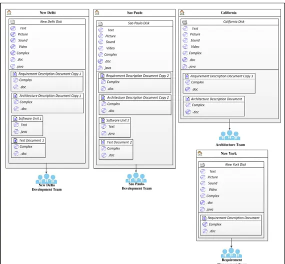
Consider the example given in above sections. In the default way, each site has its own data storage and if some data is supposed to be shared, a local copy of the original data is created using a version control software like SVN. Suppose that the example follows the default way: New York, California, New Delhi and Sao Paulo sites have their local data storages and each site has its own documents and local copies of other necessary documents kept in these local storages. This situation is described in Figure 5.4.
38
Figure 5.4 Data View: Example Case
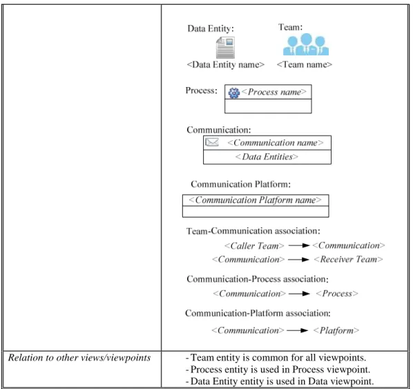
5.6 Communication Viewpoint
Teams’ communications during GSD project is captured in Communication Viewpoint. The guide of this viewpoint is in Table 5.6.
Viewpoint Element Description
Name Communication Viewpoint
Element Types Team, Communication, Process, Data Entity,
Communication Platform
Relation Types has caller as, has receiver as, carries, aims, done over
Properties of Elements All elements: name, description, id
Topology Constraints -None.
39
Relation to other views/viewpoints -Team entity is common for all viewpoints.
-Process entity is used in Process viewpoint. -Data Entity entity is used in Data viewpoint. Table 5.6 Communication Viewpoint
Figure 5.5 shows an example view from the communication activities scenario of Requirement Analysis and Architecture Teams. After Requirement Team’s Requirement Description Document production, Architecture Team receives the document and reviews it in order to create Architecture Description Document. During reviewing process, some questions are aroused and Architecture Team sends and gets reply of a bunch of emails to Requirement Team. When the textual communication is not enough to express ideas or feelings, Architecture Team makes phone calls, too.
40
Figure 5.5 Communication View: Example Case
5.7 Tool Viewpoint
In order to provide some services and achieve communication, teams in GSD projects use tools. Tool Viewpoint aims to capture this tool usage. This viewpoint’s guide is presented in Table 5.7.
Viewpoint Element Description
Name Tool Viewpoint
Element Types Communication Platform, Function Platform, Team,
Digital Format, Actual Format, Tool
Relation Types used by, consists of, compatible with
Properties of Elements All elements: name, description, id
Tool: supportCollaboration
41 Notation
Relation to other views/viewpoints -Team entity is common for all viewpoints.
-Actual and Digital Formats are used in Data Viewpoint.
-Communication Platform is used in Communication Viewpoint. Table 5.7 Tool Viewpoint
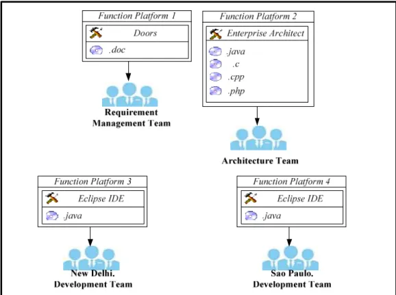
As an example, we will provide the tool usage under the environment settings given in above examples. There are four sites of this example project, and each site has its own tools for serving particular purposes. Requirement Team uses Doors [3] in order to manage requirements, Architecture Team makes their designs in Enterprise Architect [4], Development Teams build their software using Eclipse Integrated Development Environment [5] and Test Teams also use Eclipse IDE, too.
42
Figure 5.6 Tool View: Example Case
The figure above presents the tool usage of teams for providing main functionalities. One can use viewpoint definition in order to show communication tool usage, too. In this example, we keep the function platforms separate from the communication platforms to purify the ideas that we wish to express.
5.8 Migration Viewpoint
Migration Viewpoint has the functionality of representing traveling activities of
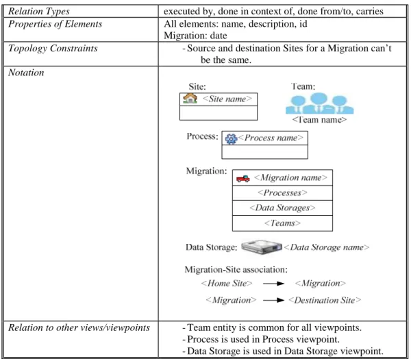
GSD teams during project life cycle. Viewpoint guide of Migration Viewpoint is shown in Table 5.8.
Viewpoint Element Description
Name Migration Viewpoint
43
Relation Types executed by, done in context of, done from/to, carries
Properties of Elements All elements: name, description, id
Migration: date
Topology Constraints -Source and destination Sites for a Migration can’t
be the same.
Notation
Relation to other views/viewpoints -Team entity is common for all viewpoints.
-Process is used in Process viewpoint.
-Data Storage is used in Data Storage viewpoint. Table 5.8 Migration Viewpoint
As an example of Migration view, we will reconsider the case described in the previous sections. Suppose that for clarifying requirements and coordinating architecture design activities, Requirement Team processes a travel from New York, where they are located, to California to come together with Architecture Team. The travel is done in the context of Requirement Management and Architecture Design. Requirement Team also carries an external disk in order to carry some information that may be needed. This migration activity is shown in
44
Figure 5.7 Migration View: Example Case
![Table 2.1 Software Engineer Salaries of Some GSD Participant Countries [16]](https://thumb-eu.123doks.com/thumbv2/9libnet/5571199.108880/22.892.301.655.277.541/table-software-engineer-salaries-gsd-participant-countries.webp)