Polymeric waveguide Bragg grating
filter using soft lithography
Askin Kocabas, Atilla Aydinli
T¨urk Telekom Bilkent Laboratory, Department of Physics, Bilkent University, 06800 Ankara, Turkey
[email protected] http://www.fen.bilkent.edu.tr/∼iogroup/
Abstract: We use the soft lithography technique to fabricate a polymeric
waveguide Bragg grating filter. Master grating structure is patterned by e-beam lithography. Using an elastomeric stamp and capillary action, uniform grating structures with very thin residual layers are transferred to the UV curable polymer without the use of an imprint machine. The waveguide layer based on BCB optical polymer is fabricated by conventional optical lithography. This approach provides processing simplicity to fabricate Bragg grating filters.
© 2006 Optical Society of America
OCIS codes: (050.2770) Gratings; (250.5460) Polymer waveguides-fibers
References and links
1. S. Y. Chou, P. R. Krauss and P. J. Renstrom, “Imprint lithography with 25-nanometer resolution,” Science.
272,85-87 (1996).
2. A. Kumar and G. M. Whitesides, “Features of gold having micrometer to centimeter dimensions can be formed through a combination of stamping with an elastomeric stamp and an alkanethiol “ink” followed by chemical etching,” Appl. Phys. Lett. 63, 2002-2004 (1993).
3. Y. Xia and G. M. Whitesides, “Soft lithography,” IEEE Photon. Technol. Lett. 17, 2122-2124 (2005).
4. L. A. Rogers, M. Meier, A. Dodabalapur, E. J. Laskowski and M. A. Cappuzzo, “Distributed feedback ridge waveguide lasers fabricated by nanoscale printing and molding on nonplanar substrates,” Appl. Phys. Lett. 74, 3257-3259 (1999).
5. Y. Huang, G. T. Paloczi, A. Yariv, C. Zhang, L. R. Dalton, “Fabrication and replication of polymer integrated optical devices using electron-beam lithography and soft lithography ,” J. Phys. Chem. B 108, 8606-8613 (2004). 6. G. T. Paloczi, Y. Huang, A. Yariv, J. Luo and A. K. Y. Jen, “Replica-molded electro-optic polymer Mach-Zehnder
modulator,” Appl. Phys. Lett. 85, 1662-1664 (2004).
7. A. Perentos, G. Kostovski, and A. Mitchell, “Polymer long-period raised rib waveguide gratings using nano-imprint lithography,” IEEE Photon. Technol. Lett. 17, 2595-2597 (2005).
8. W. H. Wong, E. Y. B. Pun, “Polymeric waveguide wavelength filter using electron-beam direct writing,” Appl. Phys. Lett. 79, 3576-3578 (2001).
9. L. Eldada, S. Yin, C. Poga, C. Glass, R. B. Blomquist and R. A. Norwood, “Integrated multichanel OADM’s using polymer Bragg grating MZI’s,” IEEE Photon. Technol. Lett. 10, 1416-1418 (1998).
10. S. W. Ahn, K. D. Lee, D. H. Kim, and S. S. Lee, “Polymeric waveguide filter based on Bragg grating nanoimprint technique,” IEEE Photon. Technol. Lett. 17, 2122-2124 (2005).
11. T. W. Odom, J. C. Love, D. W. Wolfe, K. E. Paul, and G. M. Whitesides, “Improved pattern trancfer in soft lithography using composite stamp” Langmuir. 18, 5314-5320 (2002).
12. V. V. Wong, J. Ferrera, J. N. Damask, T. E. Murphy, H. I. Smith and H. A. Haus, “Distributed Bragg grating integrated-optical filters: Synthesis and fabrication,” J. Vac. Sci. Technol. B 13, 2859-2864 (1995).
13. L.Zhu, Y. Huang, W. Green, and A. Yariv, “Polymeric multi-channel bandpass filters in phase-shifted Bragg waveguide grating by direct electron beam writing,” Opt. Express 12, 6372-6376 (2004).
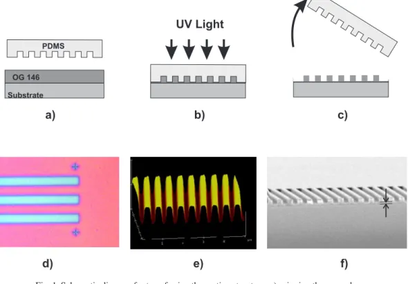
Fig. 1. Schematic diagram for transferring the grating structure; a) spinning the pre-polymer on the wafer, b) placing the PDMS stamp on pre-polymer layer and exposing with UV light, c) removing the elastomeric stamp from the wafer, d) optical microscope image of the patterned region, e) AFM image of the grating structure, f) SEM image of the grating structure with residual layer indicated.
1. Introduction
Over the past decade, due to the possibility of achieving high resolution, high fidelity and oper-ational simplicity extensive research have been done to improve the unconventional fabrication techniques such as nanoimprinting [1], self assembling [2] and soft lithography [3]. In soft lithography, an elastomeric stamp is used as a mold to transfer the desired pattern. Chemically inertness and the elastic behavior of the PDMS (poly-dimethylsiloxane) make it the main ma-terial for soft lithography. Previously, this technique has been applied to fabricate a number of optical devices such as optical couplers, polymeric lasers [4], resonators [5] and modulators [6] and long period gratings [7].
Bragg grating based wavelength filters are essential components of optical communication systems. These kinds of devices consist of a guiding layer and a periodic refractive index per-turbation through the guiding layer. For use in telecommunication applications at 1500 nm wavelength region, polymer based Bragg grating filters should have a periodicity of around Λ= 500nm. Due to the requirement of fabricating sub-micron features, e-beam [8] and in-terference lithography [9] are generally used. When light is launched into the grating loaded waveguide, wavelength corresponding toλ = 2ne f fΛis reflected back and a stop band is ob-served in the transmission spectrum. Recently, Ahn et al [10] fabricated Bragg grating filters using the nanoimprint technique. In their approach, they fabricated a UV transparent quartz stamp and using a nanoimprint machine they successfully transferred the grating pattern onto
the polymer layer. Replacing quartz stamp with a soft elastomeric material is cost effective and results in simplicity to fabricate a stamp. However, due to the elastomeric behavior, the stamp may deform and create unwanted perturbations on the desired pattern. Additionally, nonuni-form pressure distribution and shrinkage during cure may be expected to create an undesired index modulation on the waveguide. This perturbation may destroy the Bragg resonance pro-file when the grating filter is fabricated. In a Bragg grating filter, shape and the strength of resonance depends on the waveguide parameters. A sharp resonance requires high index uni-formity throughout the grating and the waveguide. This drawback may restrict the use of soft lithography in fabricating a Bragg grating filter.
In this paper, we present an approach that overcomes this drawback and allows us to fabricate a grating based wavelength filter using soft lithography. We use a soft elastomeric stamp to transfer the grating pattern onto the UV curable polymer. Using the conformal contact between substrate and the elastomeric stamp and capillary force, we were able to fabricate very uniform grating structures on very thin residual layers without using any imprint machine. Finally, the optical waveguide was fabricated by using conventional optical lithography.
2. Fabrication
The fabrication procedure for transferring the grating layer is shown in Fig. 1. The fabrication process is as follows; master structure with the grating pattern was written by e-beam lithog-raphy on a silicon wafer and subsequently this grating pattern was transferred onto the silicon wafer by reactive ion etching. The periodicity, depth, width, the length and duty cycle of the grooves are 515 nm, 200 nm, 100µm, 2 cm and 0.5 respectively. The elastomeric stamp was fabricated by well known replication procedure using PDMS (Sylgard 184, Dow Corning). To make the elastomeric stamp, liquid PDMS is poured on top of the master grating and cured for 2 h at 75 °C . After the curing procedure, elastomeric mold is peeled from the master grating. Due to the low Young’s modulus of PDMS, feature sizes that can be obtained on PDMS are limited. For our purposes single layer 5 mm thick PDMS Sylgard 184 is enough to replicate the grating. To improve the pattern quality further, composite stamps can also be used [11].
The elastomeric stamp having a grating on its surface was then used to transfer the pattern onto the UV curable low viscosity pre-polymer (OG 146, Epoxy Technology). OG 146 has low viscosity of around 40 cps. Initially, uncured pre-polymer was spin-coated onto the silicon wafer with 7µm thermal oxide on its top surface. The initial thickness of the pre-polymer is around 1µm. Then, PDMS stamp was placed on the pre-polymer without any applied pressure. Due to the conformal contact, PDMS stamp attached to the polymer coated surface. The OG 146 fills the grooves of the PDMS stamp due to the capillary action in a matter of seconds. While the stamp was kept in contact, the sample was illuminated with UV light for 5 minutes. This illumination cured the pre-polymer and after the cure, PDMS was mechanically removed while leaving the solid polymer grating structure on the substrate.
In order to asses the uniformity and measure the thickness of the residual layer grating struc-ture was transferred onto the silicon wafer. Figure 1(d) shows the optical microscope image of the transferred grating pattern. As seen in Fig. 1(d) the grating structure is very uniform through the wafer. Fig. 1(f) represents the SEM image of the grating cross-section. The depth of the grating grooves are around 200 nm and the thickness of the residual layer is around 100 nm. The thickness of the residual layer depends on the initial thickness of the pre-polymer layer. The AFM image of the transferred polymer grating pattern is shown in Fig. 1(e). The grating has a measured depth of 200 nm. Due to thermal contraction of the PDMS during cure, there is a 1-3% decrement in the periodicity of the PDMS grating. This decrement depends on the curing temperature and can be controlled. This feature may be useful in tuning the periodicity within ∼ -10 nm and the corresponding Bragg resonance wavelength in ∼ -30 nm range.
Fig. 2. Cross-sectional view of the polymeric waveguide Bragg grating filter. The grating structure is on the 7µm thick thermal oxide, the core of the wave guide is BCB and the upper cladding is PMGI, dimensions are inµm.
Cross-sectional view of the waveguide structure is shown in Fig. 2 . The core of the waveg-uide is fabricated using the BCB polymer. 3µm un-cured BCB layer was spin coated on the wafer which has a grating layer on top. BCB layer was then cured for 3 h at 250 C. Grating structure preserved its shape during the this curing procedure. Using conventional photolithog-raphy single mode waveguide was subsequently defined on the polymer and transferred into the BCB using reactive ion etching. Finally, a 3µm thick PMGI was spin coated on the waveguide structure as an upper cladding. The end facets of the waveguide with length of 1.5 cm were cleaved to couple the light. Refractive indices of the BCB, PMGI, and OG146 are 1.53, 1.50 and 1.51 at 1.5µm wavelength respectively.
Fig. 3. Transmission spectrum of the waveguide grating filter a) TM polarization, ne f f=1.515 and∆n=0.002 from fitting results b) TE polarization, ne f f=1.517 and∆n=0.002
from fitting results.
3. Measurements and results
The transmission characteristics of the filter was measured using a wavelength tunable laser diode source (Santec TSL-320). Laser light was fed through a polarizer and input into the waveguide using a tapered fiber. The wavelength was scanned between 1500 nm and 1600 nm range with 10 pm resolution and the transmitted laser light was collected with a microscope objective and measured with a power meter. Fig. 3 shows the normalized transmission of the filter for both TM and TE polarization as a function of the wavelength. As seen in Fig. 3, a
resonance was observed around 1528.2 nm for TM and 1529.7 nm for TE polarization. The 3 dB bandwidth of the resonance is 1.5 nm and reflectivity is around 20 dB for a grating with a length of 1.5 cm. Using transfer matrix method and fitting the measured results, index modulation was calculated. Grating index modulation is∆n=0.002 for both TM and TE polarizations. Uniform index perturbation through the grating structure caused sidelobes which were observed at the edges of the resonance. Also a small transmission noise appeared inside the reflection band. This noise comes mainly from the error in positioning of the grating grooves. It is known that, during e-beam writing of the master grating, displacement error occurs between the fields [12]. These displacement errors create additional phase shifts and hence noise in the transmission gap[13].
4. Conclusion
In conclusion, the work described in this report illustrates a new approach to fabricate Bragg grating based polymeric waveguide filters using the soft lithography technique. Using the prop-erties of conformal contact of the PDMS stamp and the capillary effect between stamp and liquid pre-polymer, we were able to transfer grating structures without the use of an imprint machine. This approach may also be useful to fabricate add-drop multiplexers which include multi period structures that are difficult to fabricate using conventional techniques.
Acknowledgments
The authors gratefully acknowledge the financial support of Turkish Scientific and Technical Research Council (TUBITAK), Grant no: 104M421.