© TÜBİTAK
doi:10.3906/elk-2004-19 h t t p : / / j o u r n a l s . t u b i t a k . g o v . t r / e l e k t r i k /
Research Article
Field-of-view optimization of magnetically actuated 2D gimballed scanners
Gökçe AKÖZ, Y. Dağhan GÖKDEL∗Department of Electrical and Electronics Engineering, Faculty of Engineering and Natural Sciences, İstanbul Bilgi University, İstanbul, Turkey
Received: 03.04.2020 • Accepted/Published Online: 10.08.2020 • Final Version: 25.09.2020
Abstract: This work presents the field of view (FOV) maximization of a magnetically actuated two-dimensional (2D)
gimballed scanner. The process of maximization is completed in two steps. (1) Optimization of the electrocoil providing the magnetic force that moves the scanner and (2) precise choice of optimum respective locations of both the scanner and the electrocoil. We first derived a formula relating the generated magnetic flux density, coil design parameters and driving voltage. Subsequently, we discussed the design trade-offs of an actuating electrocoil. We also conducted several experiments on a stainless steel 430 scanner having a footprint of 15 mm × 15 mm and a thickness of 460 µm . We determined the precise locations for the system components producing the maximum total optical scan angle (TOSA) hence the largest FOV. Finally, we proposed an empirically demonstrated formula, p(x1, y1)≈ p(0.25Ls+ 0.25Lm) , for
the optimum electrocoil location with respect to the scanner by providing an offset ∆ x and ∆ y from the center to be able to successfully maximize the displacement and the related total optical scan angle of the system.
Key words: Microscanner, magnetic actuation scheme, electrocoil, total optical scan angle (TOSA), field of view (FOV),
experimental optimization
1. Introduction
Microelectromechanical systems (MEMS) laser scanners are an essential part of various imaging systems and they specifically play an important role in miniaturized projection displays and biomedical imaging devices [1]. There are many reported studies in the literature on MEMS laser scanners, optical waveguides and resonators that comprehensively discuss their performance requirements and actuation principles [1–5]. Among many performance requirements discussed in the literature, having a TOSA and hence a FOV as large as possible is one of the most important and challenging tasks for laser scanners especially in miniaturized projection display applications [2,6].
In MEMS laser scanning application, various actuation methods such as electrostatic [7], magnetic [8–10], piezoelectric [11] and thermal [12] actuation are frequently employed. Among these actuation methods, magnetic actuation is preferred in applications where delivering a substantial actuation force is capable of generating larger displacements with low-power dissipation [13]. Additionally, the magnetic actuation method considerably eases the related fabrication process by simply avoiding electrical contacts on microstructures. Thus, magnetic actuation schemes are often favored especially in MEMS laser scanning applications [14]. Furthermore, there exist many different magnetic actuation schemes in MEMS technology. These schemes can be broadly classified into three different groups based on the force generating structures located on the actuator side. These are (1) ∗Correspondence: [email protected]
moving magnet (hard magnetic) actuation [15–17], (2) moving coil (Lorentz force) actuation [18, 19] and (3) soft magnetic actuation [20–22] schemes. Since the preferred bulk fabrication material SS430 is a ferritic soft magnetic material, the soft magnetic actuation scheme inherently becomes the governing actuation mechanism in this work. However, the method recommended for the soft actuation scheme in Section7can be generalized and used in other aforementioned equivalent magnetic actuation schemes.
In many of these magnetic actuation schemes, an electrocoil, in other words; a finite length solenoid is needed. In order to get optimum performance from magnetically actuated scanners, it is critical to know the total amount of magnetic force created by this electrocoil on its axial and radial directions. Related derivations and calculations determining these axial and radial fields of a finite length solenoid are quite laborious and are carefully scrutinized in [23–26]. Finite element modeling of an electrocoil and its experimental magnetic field measurements in radial and axial directions are also reported in [27]. However, the design trade-offs of an actuating electrocoil is not priorly discussed in the literature. On the other hand, in a magnetic actuation scheme, optimum positioning of the magnetic elements are crucial in order to deliver a large magnetic force to the actuator. Hence, the position of the soft magnetic scanner and the actuating electrocoil should be carefully chosen in a 2D gimballed scanning system. Nonetheless, there is no reported work in the literature that thoroughly investigates this maximization problem.
In that vein, we provide a magnetic equivalent circuit analogy (Section 4) for the chosen magnetic actuation scheme. Afterwards, we attempt to optimize it by dissecting the problem in two different parts that are not previously elaborated in the literature. In the first part (Section5), we try to explain how one can design or choose a more suitable electrocoil for their mode of operation and we emphasize the electrocoil design trade-offs. In the second part (Section 6), we conduct an empirical investigation to determine the precise positions of an electrocoil and a generic 2D gimballed steel scanner in order to acquire a maximum TOSA, hence a large FOV from the system. Therefore, contributions of this study can be stated as (i) discussion of a design guide and a model for an optimum air-core electrocoil to produce maximum amount of magnetic force, (ii) empirical investigation and proposition of the precise respective positions of an actuating electrocoil and a 2D gimballed stainless steel scanner to acquire a maximum amount of TOSA.
This paper is organised as follows: Section 2 shares the details of the proposed design and discusses its simulation results. Subsequently, fabrication process is elaborated in Section 3. Afterwards, the preferred magnetic actuation scheme and the electrocoil design procedure are discussed in Sections4and5, respectively. Experimental results are shared in Section6. Finally, the paper concludes with an overall discussion of findings and outputs in Section7.
2. Scanner design and simulations
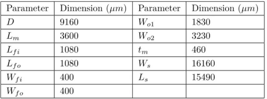
A three-dimensional (3D) illustration of the resonant mode gimballed 2D stainless steel scanner along with its dimension parameters is shown in Figure 1. As shown in this figure, Ls depicts the length of the scanner
whereas Ws illustrates the width of it. Lf i and Lf o represent the related length of inner and outer flexural
beams, respectively. Additionally, Wf i and Wf o are the width of the same flexures while tm, D and Lm are
the thickness, width and length of the inner mirror, respectively. Finally, Wo1 and Wo2 are the related width
of outer frame as depicted in Figure1b.
The scanner that is illustrated in Figure1 has a typical gimballed scanner geometry that is frequently reported in the literature [20, 28–31]. It is capable of executing a raster scan pattern in orthogonal axes.
the scanner makes a resonant torsional movement both in fast- and slow-scan axes as indicated in the figure. This geometry is preferred as a consequence of its well-documented behaviour, its simplicity and suitability for magnetic actuation experiments and the subsequent actuation optimization process. Additionally, relative dimensions of the employed steel scanner are tabulated in Table 1. Note that the presented conventional gimballed device has a floor area of 15 × 15 mm, which is only 2–3 times larger in overall die dimensions than conventional MEMS counterparts manufactured using a sophisticated and high-cost (at the development stage) microfabrication routine. Ls D Lm Lfi tm Anchor Flexure beam Slow-Scan Axis Outer Frame Inner Mirror Wfi Anchor x y z Anchor Anchor Ws Lfo Wo 1 Wo2 Wf o Outer Frame Inner Mirror Fast-Scan Axis A A’ (a) (b)
Figure 1. 3D drawing of the proposed generic 2D gimballed steel scanner along with its dimensional parameters. Parts
(a) and (b) also show the torsional movement axis for fast- and slow-scan movements.
Table 1. Dimensions of the steel scanner.
Parameter Dimension (µm) Parameter Dimension (µm)
D 9160 Wo1 1830 Lm 3600 Wo2 3230 Lf i 1080 tm 460 Lf o 1080 Ws 16160 Wf i 400 Ls 15490 Wf o 400
The scanner design is justified by using a finite element method (FEM) simulation tools. Through simulations, resonance frequencies relative to fast- and slow-scan movements and their respective displacement values are determined. Figure 2 illustrates the torsional modes of the steel scanner that is employed in the subsequent experiments. Targeted slow- and fast-scan modes of the scanner are both torsional modes occurring at 70.56 Hz and 120.73 Hz, respectively. These two modes are used while raster scanning the projected laser beam on a 2D surface. Here, it is important to note that maximizing the TOSA values of these modes using a limited power budget and cheap actuation components is the main aim of this work.
3. Scanner fabrication
The bulk fabrication material that is selected for the designed scanner is stainless steel grade 430 (SS 430) material. As a member of stainless steel (SS) family, SS 430 belongs to ferritic group of steels. Ferritic steels
(a) (b)
Figure 2. Finite element method simulation results showing the targeted slow- and fast-scan moded of the scanner: (a)
Outer frame torsion mode 120.73 Hz and (b) inner mirror torsion mode at 70.56 Hz.
are magnetic stainless steels that contain a high ratio of chromium (Cr) and low carbon (C) content. Explicit composition of SS 430 is well-documented in the literature [32]. Today, they are mostly used in industrial equipment, kitchenware and automotive application owing to their ductility, superior resistance to corrosion and stress corosion cracking [33]. More importantly, stainless steel grade 430 is a soft magnetic material. In other words, the material does not possess a permanent and fixed magnetization vector ⃗M . It solely exhibit internal magnetization while the presence of external magnetic field ⃗Hex.
Moreover, soft magnetic materials have low remanence. In other words, a big fraction of the magnetization vector is withdrawn once saturating magnetic field intensity ⃗Hex is removed. Several advantages of soft magnetic
family materials can be stated as high efficiency, low power consumption and rapid transition. Therefore, it is imperative to optimize the actuation system to deliver a large enough saturating magnetic field intensity
⃗
Hex. This magnetic field would then magnetize the scanning structure and get a large displacement out of it.
Proposed steel scanners are fabricated using a laser cutting machine. It is known and showed that stainless steel grade 430 can be readily laser cut. During the cutting process, low heat is generated and the material properties are not significantly affected. Fabricated stainless steel grade 430 microscanner is shown in Figure3. Holes that are formed on the corners are M4 screw holes that are deliberately put there for properly fixing the scanner on a holder.
Figure 3. Image of the fabricated stainless steel grade 430 scanner. As shown, 15 mm × 15 mm active scanning area
4. Magnetic actuation scheme
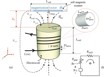
The schematic of the actuation scheme used in this study is illustrated below in Figure4. In this figure, I(ω ) is sinusoidal current signal with a frequency ω . Rsof t and Rgap are the reluctance values of the soft magnetic
material and the gap in between the scanner and the electrocoil, respectively. Finally, Lsof t is the soft magnetic
path length of the fabricated scanner.
As opposed to their hard magnetic material counterparts, the magnitude and the direction of the magnetization vector ⃗M of the soft magnetic materials depicted in Figure 4, can alternate based on both the geometry of the soft magnetic material and the applied external magnetizing field H⃗ex. In the proposed design, the tm to D ratio of the substrate is considerably small (≈ 0.1). Therefore, ignoring all other secondary
factors [34], the shape anisotropy effect becomes prevalent and the force keeps ⃗M in xy -plane. In this case, it is safe to neglect the out-of-plane components of ⃗M occurring in z-axis.
Figure 4. (a) A generic soft magnetic actuation scheme using an external off-the-shelf electrocoil and (b) its magnetic
circuit equivalent.
Moreover, small and preferably off-the-shelf electrocoils are preferred in order to provide the magnetizing field H⃗ex. In this scheme, the electrocoil is air-core, immobile and its position is fixed. The magnetic microstructure that is set in motion is typically either a ferromagnetic substrate or a thin film soft magnetic layer that is put on the main substrate by using various microfabrication technologies. It is a known fact that the nonuniform external magnetizing field ⃗Hex created by the electrocoil forms a magnetization vector ⃗M along
the thin film ferromagnetic layer obeying the BH curve peculiar to the fabrication material. It should be noted that in this study no external hard magnet is used in order to saturate this BH curve but only a small ⃗Hex is
applied. Since the freshly formed magnetization vector ⃗M seeks to align itself with the external magnetizing field ⃗Hex, a magnetic anisotropy torque ⃗T arises.
Proposed SS430 scanner and the electrocoil that is picked have typically comparable size and footprints. This introduces a nonuniform external magnetic field strength H⃗ex throughout the ferritic material forming
unsaturated regions inside the movable steel scanner where this external magnetizing field is in normal direction to the scanner. The underlying physical principles of this actuation scheme together with its governing equations are deeply elaborated in [10, 13, 14,35]. Assuming that a small sinusoidal current I(ω) with no offset value is used to drive the electrocoil and no external hard magnet is employed in order to saturate this BH curve, the magnitude, |⃗T|, becomes equal to [27]
|⃗T| = V (| ⃗M|sin(ωt))(| ⃗Hex|sin(ωt)) (1)
where V is the volume of the soft magnetic material. To enlarge the TOSA or the displacement value of the proposed steel scanner, one should increase the magnitude of the vector ⃗T exerted on it. Thus, the magnitude of the vector ⃗Hex and dependently ⃗M in this system should be augmented assuming that the volume V does
not change. Additionally, in Figure 4b the magnetic circuit equivalent of the actuation system is given. We know that the magnetic force delivered to the actuator is proportional to N I where N is the total number of turn in the electrocoil and I is the magnitude of the electrocoil drive current. Neglecting the leakage flux, it can be stated that [14]
F ≈ NI = Φ(Rsof t+ Rgap) (2)
where Φ is the magnetic flux in the equivalent magnetic circuit. In Equation 2, Rsof t and Rair are equal to:
Rsof t= Lsof t µsof tAsof t (3) Rgap= 3z0+ Lcoil− ∆z µ0Agap (4) where Lsof t is the soft magnetic path length, µsof t is the permeability of SS430 and Asof t is the cross-sectional
area of again SS430, through which the magnetic flux Φ passes. Moreover, in Equation4, µ0 and Agap signify
the permeability of the free space and the cross-sectional area of the gap between the electrocoil and the SS430 scanner, through which the flux travels, respectively. ∆z represents the dynamic distance change between the electrocoil and the scanner. Therefore, by considering Equation1to Equation4and the entire discussion above, one can state that to acquire a larger displacement and hence a bigger TOSA value using this scheme, both (1) the magnitude of ⃗Hex should be maximized by specifically designing or choosing a suitable electrocoil and (2)
the position of the electrocoil in three-dimension with respect to the steel scanner should be carefully chosen in order to maximize the torque |⃗T|.
5. Electrocoil design and measurements
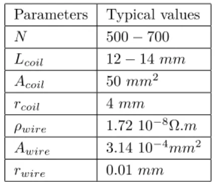
This section deals with the design and optimization of an electrocoil for magnetic actuation. A generic off-the-shelf air-core electrocoil having a cylindrical geometry is preferred in this study. Commonly used electrocoil design parameters are tabulated on Table 2 and illustrated on Figure 4. In this table, N is the number of winding. the length of the electrocoil is represented by Lcoil whereas Acoil and rcoil symbolize the
cross-sectional area and the radius of the electrocoil, respectively. Moreover, ρwire describes the resistivity of the
metal wire that is selected to wind the structure. Finally, Awire and rwire are the area and the radius of the
Table 2. Electrocoil design parameters.
Parameters Typical values
N 500− 700 Lcoil 12− 14 mm Acoil 50 mm2 rcoil 4 mm ρwire 1.72 10−8Ω.m Awire 3.14 10−4mm2 rwire 0.01 mm
Assuming a limited length for the wire, ( Lwire), no overlapping turns and tight winding conditions for
the coil, the number of turns N becomes equal to Lcoil/ 2rwire. We provide a drive current I ; which is equal
to V /Rcoil+ jXcoil into the electrocoil where Rcoil and Xcoil are the resistance and the reactance of the
electrocoil, respectively. Since the resonant frequencies of the targeted modes of the proposed steel scanner, whose values are given in Section2, are below 1 kHz, we can neglect the frequency-dependent reactance part of the electrocoil. Moreover, we derive that Rcoil is equal to 2N× (ρwirercoil)/r2wire. Therefore, the drive current
I of the actuation scheme can be written as:
I = V r
3
wire
ρwireLcoilrcoil
(5)
Therefore,using Ampère’s law and assuming that an electrocoil contains many linear paths, ⃗B can be calculated as
⃗
B = µV r
2
wire
2ρwireLcoilrcoil
(6) where µ = µ0µr. Above equation shows that the magnetic field created by the electrocoil significantly depends
on its dimensions that are tabulated on Table 2. The magnitude of the magnetic flux is strongly related to the radius of the electrical wire, rwire, the applied voltage V and the relative permeability of the magnetic
material, around which we do the winding, if used any. On the other hand, ⃗B and hence the magnetic power delivered to the actuator is inversely proportional to the resistivity of the electrocoil wire together with the radius and the length of the electrocoil.
Considering a constant permeability value and a fixed driving voltage, it is safe to state that coil dimensions to be selected play a crucial role in delivering a large magnetic actuation force to the system. It should be noted that there is a delicate trade-off in the design of an electrocoil which is suitable for the selected magnetic actuation scheme. As a rule of thumb, one should use a larger current value I and a winding number N for delivering a large value of magnetic actuation force to the scanner and hence to get a large TOSA value. In applications, we have a limited volume for the entire electrocoil and, therefore, a limited value for Lcoil and rcoil. Moreover, assuming a constant conductivity value ρwire for the wire , one can only increase
the magnitude of rwire to acquire a cubic increase in current value I as Equation5suggested.
Nonetheless, an ever-growing magnitude of rwire will automatically decrease the number of electrocoil
winding N and eventually, the magnitude of the magnetic flux ⃗B in conjunction with the above discussion. Moreover, increasing the magnitude of voltage V or dependently the current value I without enlarging the
dimensions of the electrocoil and the electrical wire and by simply keeping the number N constant will burn-out and damage the coil in the long run since Rcoil remains constant. To put it in a nutshell, there exists a
trade-off between current I and number of winding N even though it is required to have large values for both to provide a maximum level of magnetic actuation force.
Regarding the discussion above and considering the dimensions of the proposed steel scanner in Table1, magnitudes that are listed in Table2are chosen for an electrocoil with the main aim of maximizing the magnetic actuation force that would be delivering to the designed scanner. One should also note that, as a rule of thumb, a smaller footprint area for the electrocoil is preferred. Therefore an off-the-shelf electrocoil harboring roughly the same magnitudes for the above-listed design parameters is chosen in this work.
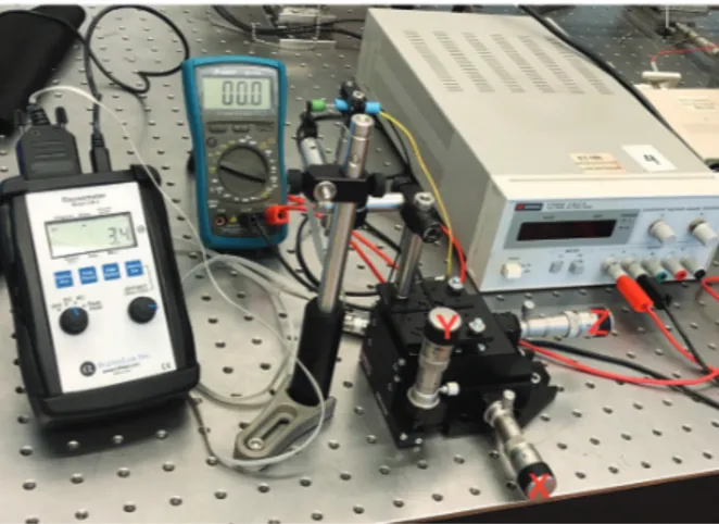
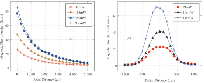
The magnetic field created by this preferred electrocoil for various magnitudes of driving power is monitored while the axial distance is increased. Required measurement are completed with the help of the Gaussmeter (Alphalab GM2). The test setup which is used in the measurements is shown in Figure 5. The acquired data is plotted in Figure6a. In this experiment, the tip of the measurement probe of this Gaussmeter is attached to an optical post which is connected to a 3D manual translational stage as shown in the figure. The tip of the probe is carefully moved away with a constant step size of 10µ m in orthogonal x, y (radial directions) and z (axial direction) directions starting from the origin, which is illustrated as the intersection of two dashed lines in Figure 4a. As it is expected, the magnitude of the magnetic field is gradually decreased while slightly augmenting the axial distance away from the electrocoil and it almost converges to zero when we are approximately 5 mm away from the origin.
Figure 5. Tabletop measurement setup used to monitor the magnitude of magnetic flux created by the preferred
electrocoil at different axial and radial distances. The setup is composed of an Alphalab GM2 Gaussmeter, a multimeter, a Keysight E3620a power supply and a Thorlabs 3D manual translational stage.
In addition to the behaviour of magnetic flux density at linearly increasing axial distances, its dependence on increasing radial distances is also monitored in Figure 6b. Magnetic flux density magnitudes are collected from a radial distance range of 2 mm while the axial distance between the electrocoil and the tip of the gaussmeter is kept at zero. As anticipated, larger values of driving power correspond to larger magnitudes of magnetic power. Moreover, Figure 6b presents bell-shaped curves for magnetic flux changing with radial distance. As the curves depict, magnitude of the magnetic flux reaches its maximum value right in the middle of the electrocoils circular cap. Afterwards, it gradually decreases and eventually converges to zero as we keep increasing the radial distance away from the electrocoil.
0 1 .000 2.000 3 .000 4 .000 5 .000 0 20 40 60 80 Axial Distance (µm) Magneti c Flu x In tensi ty (Gauss) 30mW 116mW 450mW 936mW (a) -1. 000 - 500 0 500 1.000 0 20 40 60 Radial Distance (µ m) Magneti c Flu x Densi ty (Gauss) 29mW 116mW 446mW (b)
Figure 6. (a) Magnetic flux density vs. axial distance and (b) magnetic flux density vs. radial distance for different magnitudes of electrocoil driving power
Since we have now formulated how to cleverly design and optimize an actuating electrocoil for the magnetic actuation scheme and experimentally analysed its behaviour, it is next required to investigate the proposed system and respective positions of both the electrocoil and the scanner in order to be able to efficiently transfer the actuating magnetic power to the soft magnetic microstructure.
6. Experimental results
Fabricated SS430 scanner is first characterized using a setup that includes a laser Doppler vibrometer (Polytech OFV-5000). The frequency response of the steel scanner is plotted below in Figure 7. As it is shown from the plot, the torsional displacement of the inner mirror and the outer frame peaks at 78.4 Hz and 137.2 Hz, respectively. The error percentage between the simulated and experimentally acquired results are below 14% . It is safe to state that this error is mostly stemming from the slightly alternating magnitudes of the scanner dimensions due to not so precise laser cutting process.
0 100 200 300 400 500 0 0 .05 0.1 0 .15 ( Mirror ) ( Outer frame) Frequency (Hz) Displ ace me nt (mm)
Afterwards, optimum distances, ∆x , ∆y , ∆z , and the optimum zenithal angle θ between the fabricated ferritic scanner and the proposed electrocoil are experimented in order to deliver the largest magnetic force load and hence to get the maximum amount of TOSA for the system. The system under test is illustrated in Figure 8 and photographed in Figure9. In Figure 8, parameter ∆y is not shown on this drawing but it symbolizes the distance between the coil and the scanner on an orthogonal axis. By delicately modifying the angle and the distance, we will be actually changing the magnitude of TOSA for the system both in horizontal and vertical planes and hence indirectly optimizing the magnetic equivalent circuit shown in Figure 4b.
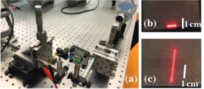
Figure9a shows the optical test setup that we used to modify the system paramaters in a controlled and precise way. Polytech OFV-5000 laser-doppler vibrometer that we have utilized in characterizing the scanner is now used as a collimated laser source to form the slow and fast scan lines that are shown in Figures 9b and9c, respectively.
Figure 8. Illustration of the scanner and the electrocoil emphasising the optimization parameters ∆x , ∆z , and zenithal
angle θ for the proposed magnetic actuation scheme.
Figure 9. Experimental test setup that is used to monitor the effect of optimization parameters on TOSA of the
system. A manual rotation stage together with two 2D micromanipulators are utilized to sweep a wide range of values for mentioned parameters.
Scan lines that occur in Figures 9b and 9c are acquired on a printable grid paper about 40 cm away from the ferritic steel scanner using an approximate electrocoil drive power of 10 mW. The scanning system does not have any saturating external magnet, hence their magnitudes are pinched in a couple of cm range. However, in order to rigorously monitor the change in TOSA while sweeping the actuation parameters that we have explicitly stated in Figure 8 and ease the measurement process, magnitudes of scan lines are measured from a distance of 3.8 m away from the scanner. The respective positions of the soft magnetic scanner and the electrocoil that is preferred in the system are carefully investigated to maximize the TOSA of the system in orthogonal axes and to form a 2D laser projected display as large as possible. As we have previously indicated in Figure 1, the torsional movement of the outer frame around the slow-scan axis forms a horizontal scan line whereas the torsional movement of the inner mirror around the fast-scan axis produces a vertical one.
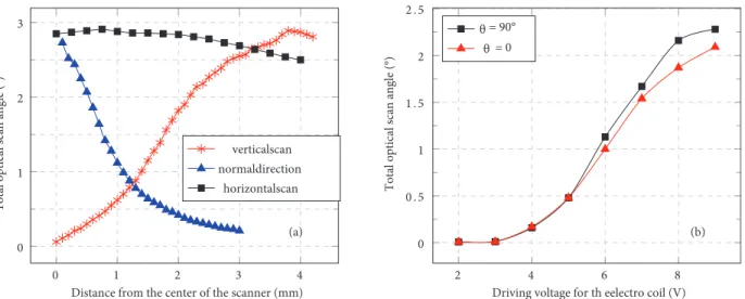
While keeping a safe and constant normal distance of 0.5 mm between the surface of the scanner and the electrocoil and assuming the center of the inner mirror as the origin (initial location of the electrocoil), the electrocoil is gently moved away from there towards the scanner extremity, following the slow-scan axis that is illustrated in Figure 1. Since the horizontal scan line of the system is occurring due to torsional movement of the outer frame around this slow-scan axis, moving away from the origin on the slow-scan axis does not have any effect on the TOSA of the horizontal scan line but it drastically changes the TOSA of the vertical scan line. We make the electrocoil move for approximately 4 mm along the slow-scan axis and as anticipated, we did not observe any considerable change in the length of the horizontal scan line whereas the TOSA of the vertical scan line starts increasing slightly up until 0.75 mm. At that location, TOSA reaches a value about 2.9◦ and thereafter gradually decreases as it is shown in Figure 10a. In the subsequent step, a similar experiment is conducted. The electrocoil swept an approximate distance of 4 mm, this time on the fast-scan axis. No variation is observed in the magnitude of the horizontal scan line. On the other hand, the TOSA value for the vertical scan line increased from 0◦ to almost 3◦ while the electrocoil is moved from the initial center point to 3.8 mm away on the axis towards the extremity of the scanner. Thereafter, a steep decrease in TOSA value is occurred as plotted in Figure10a.
Finally, the normal distance between the electrocoil and the scanner is alternated while monitoring the scanner displacement and hence the TOSA of the system. Actuating electrocoil and the scanner cannot be very close to each other and there should be a minimum safe distance in between them in order to prevent them touching each other when the inner mirror or the outer frame start to resonate. This distance is strictly based on the geometry and the maximum theoretical displacement of the scanner along with the actuating power that is delivered to the system. We iteratively determined that safe distance as 0.2 mm with the coil driving power as we have indicated earlier in this paper. When we start increasing the normal distance, the related TOSA value remarkably decreases as shown in Figure 10a. This result is expected considering the analysis that we have made in Section 5. Therefore it is better to position the electrocoil as close as possible to the moving structure. 0 1 2 3 4 0 1 2 3
Distance from the center of the scanner (mm)
Total op tica l scan angl e (°) Total op tica l scan angl e (°) verticalscan normaldirection horizontalscan (a) 2 4 6 8 0 0 . 5 1 1 . 5 2 2 . 5
Driving voltage for th eelectro coil (V) θ
θ = 0 = 90°
(b)
Figure 10. (a) Total optical scan angle (TOSA) values of the system alternating with the changing location of the
electrocoil with respect to the soft magnetic scanner. (b) Total optical scan angle (TOSA) values of the system alternating with the changing angle of the electrocoil with respect to the soft magnetic scanner surface.
Subsequently, Figure10b plots the behaviour of the steel scanner under the magnetic actuation force of the electrocoil with an alternating zenithal angle θ that is illustrated in Figure8. This angle θ is defined as the angle between the normal vectors of the scanner surface and the top cap of the electrocoil that we have used in the system. As we can expect, there is not much difference in TOSA values for low driving coil power even though we sweep θ values from 0◦ to 90◦. It should be noted that the distance ∆ z between the electrocoil and the scanner is kept fixed during these experiments. As we increase the driving voltage, we start to realize a slight rise in TOSA magnitudes for different θ values. Experiments show that placing a cylindrical electrocoil in-plane with the scanner or in other words, having θ = 90◦ slightly increases the TOSA of the system. If we keep augmenting the power delivered to the electrocoil, TOSA of the system becomes saturated and get limited with the topology and properties of the scanner under test, no matter how large the delivered magnetic power is. Therefore, as one can see from Figure 10b, TOSA curves for 0◦ and 90◦ are converging towards the same value and eventually will become equal to each other.
7. Discussion and conclusion
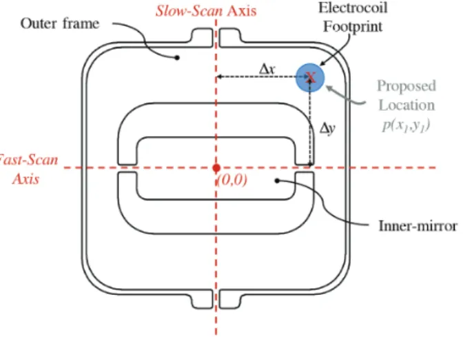
Figure 11 illustrates the suggested position of the electrocoil with respect to the ferritic two-dimensional gimballed steel scanner to deliver the maximum amount of actuating signal to the microstructure. The proposed position of the actuating electrocoil is determined by referring to the experimental data collected and analysed in Section 6. Considering our scanner geometry and dimensions along with the form and properties of the electrocoil; and assuming that the center of the inner mirror is the origin point (0,0) of our system as illustrated in Figure 11, the optimized electrocoil locations should be approximately at (3.8 mm, 0.2 mm, 0.75 mm) to maximize the displacement hence the TOSA for our specific case. Therefore, it is ill-advised to locate the electrocoil right at the center of the scanning system, in other words, on point (0,0). In brief, we should always provide an offset ∆ x and ∆y to be able to successfully maximize the displacement and the related TOSA.
Figure 11. Proposed electrocoil location with respect to the two-dimensional gimballed ferritic steel scanner.
For instance in our case, this minor change in the location of the electrocoil increases the TOSA value of vertical scan from virtually 0◦ ( 0.06◦) to almost 2.9◦ even though a moderate power of 10 mW is used to drive the electrocoil. As a rule of thumb, this can be generalized by stating that the proposed location p(x1, y1) for the electrocoil can be roughly determined as given below.
where Ls is the length or the diameter of the outer frame and Lm is the length or the diameter of the inner
mirror. Furthermore, in normal direction, the scanner and the electrocoil should be as close as possible. However, possible contact of these components should be prevented and a safe distance has to be provided in between them considering the resonant mode displacement of the scanner.
Moreover, observations show that the zenithal angle θ which is defined as the angle between the normal vectors of the scanner surface and the top cap of the electrocoil should be converging to 90◦ to acquire a slightly larger displacement from the moving structure. Considering the magnetic anisotropy of the ferritic structure, rotating the electrocoil eases the magnetization since in this case the easy-axis of the soft magnetic structure and the magnetizing field vectors of the electrocoil are coinciding. To conclude, this work is significant in two-folds: (1) a model for an optimum air-core electrocoil to deliver maximum amount of magnetic force is provided and (2) an empirical investigation for the precise positions of an actuating electrocoil and a 2D gimballed ferritic scanning structure to acquire a maximum TOSA is elaborated.
References
[1] Holmström ST, Baran U, Urey H. MEMS laser scanners: a review. Journal of Microelectromechanical Systems 2014; 23 (2): 259-275. doi: 10.1109/JMEMS.2013.2295470
[2] Chellappan KV, Erden E, Urey H. Laser-based displays: a review. Applied optics 2010; 49 (25): F79-F98. doi: 10.1364/AO.49.000F79
[3] Hofmann U, Janes J, Quenzer HJ. High-Q MEMS resonators for laser beam scanning displays. Micromachines 2012; 3 (2): 509-528. doi: 10.3390/mi3020509
[4] Taya SA. Dispersion properties of lossy, dispersive, and anisotropic left-handed material slab waveguide. Optik 2015; 126 (14): 1319-1323. doi: 10.1016/j.ijleo.2015.04.013
[5] Taya SA, El-Agez TM. Optical sensors based on Fabry–Perot resonator and fringes of equal thickness structure. Optik 2012; 123 (5): 417-421. doi: 10.1016/j.ijleo.2011.04.020
[6] Urey H. Torsional MEMS scanner design for high-resolution scanning display systems. In: Optical Scanning, International Symposium on Optical Science and Technology; Seattle, WA, United States; 2002. pp. 27-37. [7] Hung ACL, Lai HYH, Lin TW, Fu SG, Lu MSC. An electrostatically driven 2D micro-scanning mirror
with capacitive sensing for projection display. Sensors and Actuators A: Physical 2015; 222: 122-129. doi: 10.1016/j.sna.2014.10.008
[8] Ataman Ç, Lani S, Noell W, De Rooij N. A dual-axis pointing mirror with moving-magnet actuation. Journal of Micromechanics and Microengineering 2012; 23 (2): 025002. doi: 10.1088/0960-1317/23/2/025002
[9] Yi YW, Liu C. Magnetic actuation of hinged microstructures. Journal of Microelectromechanical Systems 1999; 8 (1): 10-17. doi: 10.1109/84.749397
[10] Niarchos D. Magnetic MEMS: key issues and some applications. Sensors and Actuators A: Physical 2003; 109 (1-2): 166-173. doi: 10.1016/j.sna.2003.09.010
[11] Filhol F, Defay E, Divoux C, Zinck C, Delaye MT. Resonant micro-mirror excited by a thin-film piezoelec-tric actuator for fast optical beam scanning. Sensors and Actuators A: Physical 2005; 123: 483-489. doi: 10.1016/j.sna.2005.04.029
[12] Jain A, Qu H, Todd S, Xie H. A thermal bimorph micromirror with large bi-directional and vertical actuation. Sensors and Actuators A: Physical 2005; 122 (1): 9-15. doi: 10.1016/j.sna.2005.02.001
[14] Wang Y, Gokdel YD, Triesault N, Wang L, Huang YY et al. Magnetic-actuated stainless steel scanner for two-photon hyperspectral fluorescence microscope. Journal of Microelectromechanical Systems 2014; 23 (5): 1208-1218. doi: 10.1109/JMEMS.2014.2308573
[15] Ryan P, Diller E. Magnetic actuation for full dexterity microrobotic control using rotating permanent magnets. IEEE Transactions on Robotics 2017; 33 (6): 1398-1409. doi: 10.1109/TRO.2017.2719687
[16] Park B, Afsharipour E, Chrusch D, Shafai C, Andersen D et al. Large displacement bi-directional out-of-plane Lorentz actuator array for surface manipulation. Journal of Micromechanics and Microengineering 2017; 27 (8): 085005. doi: 10.1088/1361-6439/aa7970
[17] Cho HJ, Ahn CH. A bidirectional magnetic microactuator using electroplated permanent magnet arrays. Journal of Microelectromechanical Systems 2002; 11 (1): 78-84. doi: 10.1109/84.982866
[18] Yan J, Luanava S, Casasanta V. Magnetic actuation for MEMS scanners for retinal scanning displays. In: MOEMS Display and Imaging Systems, International Society for Optics and Photonics; San Jose, CA, United States; 2003. pp. 115-120.
[19] Bernstein JJ, Taylor WP, Brazzle JD, Corcoran CJ, Kirkos G et al. Electromagnetically actuated mirror arrays for use in 3-D optical switching applications. Journal of Microelectromechanical Systems 2004; 13 (3): 526-535. doi: 10.1109/JMEMS.2004.828705
[20] Gokdel YD, Sarioglu B, Mutlu S, Yalcinkaya AD. Design and fabrication of two-axis micromachined steel scanners. Journal of Micromechanics and Microengineering 2009; 19 (7): 075001. doi: 10.1088/0960-1317/19/7/075001 [21] Thiruvengadam V, Vitta S. Flexible bacterial cellulose/permalloy nanocomposite xerogel sheets–Size scalable
mag-netic actuator-cum-electrical conductor. Aip Advances 2017; 7 (3): 035107. doi: 10.1063/1.4977558
[22] Inomata N, Suwa W, Van Toan N, Toda M et al. Resonant magnetic sensor using concentration of magnetic field gradient by asymmetric permalloy plates. Microsystem Technologies 2019; 25 (10): 3983-3989. doi: 10.1007/s00542-018-4257-8
[23] Garrett MW. Axially symmetric systems for generating and measuring magnetic fields. Part I. Journal of Applied Physics 1951; 22 (9): 1091-1107. doi: 10.1063/1.1700115
[24] Callaghan EE, Maslen SH. The magnetic field of a finite solenoid. Washington, USA: Work of the US Gov. Public Use Permitted, 1960.
[25] Taddese AZ, Slawinski PR, Pirotta M, De Momi E, Obstein KL et al. Enhanced real-time pose estimation for closed-loop robotic manipulation of magnetically actuated capsule endoscopes. The International Journal of Robotics Research 2019; 37 (8): 890-911. doi: 10.1177/0278364918779132
[26] Derby N, Olbert S. Cylindrical magnets and ideal solenoids. American Journal of Physics 2010; 78 (3): 229-235. doi: 10.1119/1.3256157
[27] Isikman SO, Urey H. Dynamic modeling of soft magnetic film actuated scanners. IEEE Transactions on Magnetics 2009; 45 (7): 2912-2919. doi: 10.1109/TMAG.2009.2014947
[28] Murakami K, Kamiya Y, Karatsu K, Miyajima H, Katashiro M. A MEMS gimbal scanner for a miniature confocal microscope. In: IEEE/LEOS International Conference on Optical MEMs; Lugano, Switzerland; 2002. pp. 9-10. [29] Davis WO, Sprague R, Miller J. MEMS-based pico projector display. In: 2008 IEEE/LEOS International Conference
on Optical MEMs and Nanophotonics; Redmond WA, USA; 2008. pp. 31-32.
[30] Fujita T, Maenaka K, Takayama Y. Dual-axis MEMS mirror for large deflection-angle using SU-8 soft torsion beam. Sensors and Actuators A: Physical 2005; 121 (1): 16-21. doi: 10.1016/j.sna.2005.01.029
[31] Aguirre AD, Herz PR, Chen Y, Fujimoto JG, Piyawattanametha W et al. Two-axis MEMS scanning catheter for ultrahigh resolution three-dimensional and en face imaging. Optics express 2007; 15 (5): 2445-2453. doi: 10.1364/OE.15.002445
[32] Bateni MR, Wei P, Deng X, Petric A. Spinel coatings for UNS 430 stainless steel interconnects. Surface and Coatings Technology 2007; 201 (8): 4677-4684. doi: 10.1016/j.surfcoat.2006.10.011
[33] Van Zwieten ACTM, Bulloch JH. Some considerations on the toughness properties of ferritic stainless steels—a brief review. International Journal of Pressure Vessels and Piping 1993; 56 (1): 1-31. doi: 10.1016/0308-0161(93)90114-9 [34] Judy JW, Muller RS. Magnetic microactuation of torsional polysilicon structures. Sensors and Actuators A: Physical
1996; 53 (1-3): 392-397. doi: 10.1016/0924-4247(96)01138-7
[35] Tilmans HA. Equivalent circuit representation of electromechanical transducers: I. Lumped-parameter systems. Journal of Micromechanics and Microengineering 1996; 6 (1): 157. doi: 10.1088/0960-1317/6/1/036