AUTOMATIC DETECTION OF SALIENT
OBJECTS FOR A VIDEO DATABASE
SYSTEM
A THESIS
SUBMITTED TO THE DEPARTMENT OF COMPUTER ENGINEERING AND INFORMATION SCIENCE AND THE INSTITUTE OF ENGINEERING AND SCIENCE
OF B˙ILKENT UNIVERSITY
IN PARTIAL FULFILLMENT OF THE REQUIREMENTS FOR THE DEGREE OF
MASTER OF SCIENCE
By
Tarkan Sevilmi¸s
November, 2005
I certify that I have read this thesis and that in my opinion it is fully adequate, in scope and in quality, as a thesis for the degree of Master of Science.
Asst. Prof. Dr. U˘gur G¨ud¨ukbay (Supervisor)
I certify that I have read this thesis and that in my opinion it is fully adequate, in scope and in quality, as a thesis for the degree of Master of Science.
Prof. Dr. ¨Ozg¨ur Ulusoy (Co-supervisor)
I certify that I have read this thesis and that in my opinion it is fully adequate, in scope and in quality, as a thesis for the degree of Master of Science.
Prof. Dr. Enis C¸ etin
I certify that I have read this thesis and that in my opinion it is fully adequate, in scope and in quality, as a thesis for the degree of Master of Science.
Asst. Prof. Dr. U˘gur Do˘grus¨oz
I certify that I have read this thesis and that in my opinion it is fully adequate, in scope and in quality, as a thesis for the degree of Master of Science.
Asst. Prof. Dr. Selim Aksoy
Approved for the Institute of Engineering and Science:
Prof. Dr. Mehmet B. Baray Director of the Institute
ABSTRACT
AUTOMATIC DETECTION OF SALIENT OBJECTS
FOR A VIDEO DATABASE SYSTEM
Tarkan Sevilmi¸s
M.S. in Computer Engineering
Supervisors: Asst. Prof. Dr. U˘gur G¨ud¨ukbay and Prof. Dr. ¨Ozg¨ur Ulusoy
November, 2005
Recently, the increase in the amount of multimedia data has unleashed the devel-opment of storage techniques. Multimedia databases is one of the most popular of these techniques because of its scalability and ability to be queried by the media features. One downside of these databases is the necessity for processing of the media for feature extraction prior to storage and querying. Ever growing pile of media makes this processing harder to be completed manually. This is the case with BilVideo Video Database System, as well. Improvements on computer vision techniques for object detection and tracking have made automation of this tedious manual task possible. In this thesis, we propose a tool for the automatic detection of objects of interest and deriving spatio-temporal relations between them in video frames. The proposed framework covers the scalable architecture for video processing and the stages for cut detection, object detection and track-ing. We use color histograms for cut detection. Based on detected shots, the system detects salient objects in the scene, by making use of color regions and camera focus estimation. Then, the detected objects are tracked based on their location, shape and estimated speed.
Keywords: Video Databases, Video Object Detection, Object Tracking, Camera Focus Estimation.
¨
OZET
G ¨
OR ¨
UNT ¨
U VER˙ITABANI S˙ISTEM˙I ˙IC
¸ ˙IN ¨
ONEML˙I
NESNELER˙IN OTOMAT˙IK OLARAK BULUNMASI
Tarkan Sevilmi¸s
Bilgisayar M¨uhendisli˘gi, Y¨uksek Lisans
Tez Y¨oneticileri: Yrd. Do¸c. Dr. U˘gur G¨ud¨ukbay and Prof. Dr. ¨Ozg¨ur Ulusoy
Kasım, 2005
Son zamanlardaki ¸coklu ortam bilgi artı¸sı, bu bilgileri saklama tekniklerinin geli¸smesine yol a¸cmı¸stır. C¸ oklu ortam veritabanları, ¨ol¸ceklenebilir olma ve or-tam ¨ozelliklerine g¨ore sorgulanabilme ¨ozellikleri ile bu tekniklerin en pop¨uleri olmu¸slardır. Bu veritabanlarının bir k¨ot¨u yanı ise saklama ve sorgulamadan ¨once ortamların ¨ozelliklerinin ayrı¸stırılması i¸cin i¸slenmesi gereksinimidir. S¨urekli artan ortamlar yı˘gını bu i¸slenmenin elle yapılmasını zorla¸stırmaktadır. G¨or¨unt¨u Veri-tabanı sistemimiz BilVideo i¸cin de durum b¨oyledir. Nesne bulma ve takip etme gibi bilgisayarlı g¨or¨u¸s tekniklerindeki geli¸smeler bu i¸slemenin otomatik olarak yapılmasına olanak vermektedir. Bu tezde, g¨or¨unt¨uden nesnelerin yerle¸sim-zaman ¨ozelliklerini otomatik olarak ayrı¸stırmak i¸cin bir ara¸c ¨onerilmektedir.
¨
Onerilen sistem, g¨or¨unt¨u i¸sleme i¸cin geli¸stirilen ¨ol¸ceklenebilir mimariyi ve resim sınırı bulma, nesne bulma ve takip etme i¸cin kullandı˘gımız y¨ontemi kapsamak-tadır. Resim sınırı bulmak i¸cin renk histogramı kullanılmı¸stır. ¨Onerilen sistem bulunan resim sınırları i¸cerisinde ¨onemli nesneleri renk b¨olgelerine ve kamera odak tahminine g¨ore bulmaktadır. Bulunan nesneler yerlerine, ¸sekillerine ve tahmini hızlarına g¨ore takip edilmektedir.
Anahtar s¨ozc¨ukler : Video veritabanları, g¨or¨unt¨ude nesne bulma, nesne takip etme, odak tahmini.
Acknowledgement
After the thesis I feel I need to thank some people. Without them and with limited time I had, this thesis would never be complete. I provide the incomplete list of names below in no particular order.
Years in MS program could not be so delightful without the warm people of the only grad school, where about 80% of the population can juggle 3 balls. Unique people that one would wish to spend more time with. I hope juggling reinforces the memories of the good time we spent together.
Both before and during MS, my advisors Asst. Prof. Dr. U˘gur G¨ud¨ukbay and Prof. Dr. ¨Ozg¨ur Ulusoy have supported my work, so I hereby express my sincere gratitude to them. Finally I want to thank everyone whose names are not enlisted here, but who have supported me either technically or non-technically.
vii
Contents
1 Introduction 1
1.1 BilVideo Video Database System . . . 2
1.2 Motivation . . . 3
1.3 System Features . . . 3
1.3.1 Object Detection Mechanism . . . 5
1.3.2 Object Tracking Mechanism . . . 5
1.3.3 Knowledge-base Construction . . . 6
1.4 Organization of the Thesis . . . 6
2 Related Work 7 2.1 Cut Detection . . . 7 2.2 Object Detection . . . 8 2.2.1 Image Segmentation . . . 8 2.2.2 Temporal Differencing . . . 10 2.2.3 Background Subtraction . . . 10 viii
CONTENTS ix 2.2.4 Optical Flow . . . 12 2.3 Object Tracking . . . 13 3 System Overview 14 3.1 Video Processing . . . 14 3.1.1 Preprocessing Codecs . . . 15 3.1.2 Utility Codecs . . . 17
3.1.3 Cut Detection Codecs . . . 17
3.1.4 Processing Codecs . . . 19
3.1.5 Non-codec Parts of Codec Chain . . . 20
3.2 Object Detection . . . 20
3.2.1 Clustering Like-colored Pixels . . . 20
3.2.2 Finding Pixel Patches . . . 22
3.2.3 Finding Regions . . . 22
3.2.4 Saliency Measure . . . 23
3.3 Object Tracking . . . 25
3.4 User Interaction and Knowledge-base Construction . . . 26
4 Performance Results 28 4.1 Cut Detection . . . 28
4.2 Object Detection . . . 29
CONTENTS x
4.4 Extraction Time . . . 32
5 Conclusion and Future Work 34 5.1 Possible Improvements . . . 34
5.1.1 Cut Detection . . . 34
5.1.2 Object Detection . . . 35
5.1.3 Object Tracking . . . 35
List of Figures
1.1 The overall architecture of BilVideo Video Database System . . . 2
2.1 Segmentation results obtained by the method proposed by Ma-hamud et al. [19] . . . 9
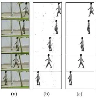
2.2 Moving object detection results obtained by the method developed by Desa and Salih. Column (a) displays original frames from the video, column (b) is the result of background subtraction, and the column (c) is the output of the program [6]. . . 11
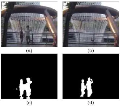
2.3 Example of background construction and subtraction from Li and Huang’s method. Actual frame from the video (a); The maintained background image (b); The output of the program (c); Hand drawn ground truth (d). [16]. . . 12
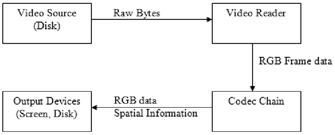
3.1 Video processing system overview. . . 15
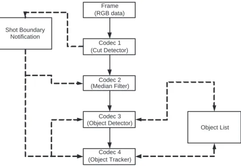
3.2 Codec chain example, consisting of 4 codecs. . . 16
3.3 The pixel clustering algorithm. . . 21
3.4 The algorithm to find pixel patches. . . 22
3.5 Example of focus effecting edge sharpness. . . 24
LIST OF FIGURES xii
4.1 An example frame from Video 1. The original frame (a); The HSV visualization of the original frame (b); The original frame after noise reduction (c); The HSV representation of the frame after noise reduction (d). . . 31 4.2 An example frame from Video 2. The original frame (a); The HSV
List of Tables
4.1 Cut detection results. . . 29 4.2 Object extraction time comparison table. . . 33
Chapter 1
Introduction
The rapid increase in the amount of multimedia data resulted in development of various technologies for handling large volumes of data. These technologies basically concentrate on efficient compression and storage of the multimedia data. One of the particularly interesting storage systems is the “multimedia database”, which stores multimedia content that can be queried by their various features [20]. There are several examples of multimedia databases, most popular of which are QBIC [10], VisualSeek [27] and VideoQ [5]. If the media type in the database is video as in our Video Database System, BilVideo, the queried features are spatial, spatio-temporal, semantic, motion (e.g., object trajectories) and object features (e.g., color, shape, texture) [24]. Before their retrieval, the videos need to be processed to extract the features that can be queried. Since the multimedia databases first come into existence, research for efficient means of extraction has become popular. To this end, some manual, semi-automatic and automatic tools have been developed [1, 21, 12, 27, 5]. This thesis focusses on methods and algorithms used in our Automatic Object Extractor tool, which is developed to detect and track objects in a given video, and contruct a list of spatio-temporal features.
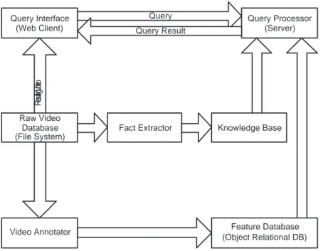
CHAPTER 1. INTRODUCTION 2 Raw Video Database (File System) Fact Extractor Feature Database (Object Relational DB) Video Annotator Knowledge Base Query Interface (Web Client) Query Processor (Server) Re su lting Vid eo Query Query Result
Figure 1.1: The overall architecture of BilVideo Video Database System
1.1
BilVideo Video Database System
BilVideo is a video database system capable of processing spatio-temporal and semantic queries. It is useful for organizing and querying multimedia data that is time dependent (especially video), which includes but not limited to television broadcast archives. BilVideo handles spatio-temporal queries using a knowledge-base, which consists of a fact-base and a comprehensive set of rules, while the queries on semantic features are handled by an object-relational database [7]. Figure 1.1 displays the overall architecture of the BilVideo video database man-agement system.
The processing of videos for spatio-temporal queries is performed by using two basic tools, Fact-Extractor and Object Extractor. Fact Extractor is used to extract spatio-temporal relations between video objects using their user-specified Mini-mum Bounding Rectangles (MBR’s) and store these relations in the knowledge-base as facts. Object-Extractor is used to extract MBR’s of salient objects from video frames and still images [7]. Extracting knowledge base from a video is a tedious task. The user, for each frame, should specify MBR’s of all salient objects
CHAPTER 1. INTRODUCTION 3
in the scene.
The knowledge base of BilVideo contains the trajectories and spatial relation-ships of the objects with the time frame this relation is preserved or trajectory is maintained. The relationship is expressed using a set of comprehensive rules, which are also used for querying the system [8]. The Query interface for BilVideo, Web Client, is responsible for generating this relationship, based on the examples the user provides.
1.2
Motivation
The Fact Extractor and the Object Extractor tools are used to construct the knowledge base for a video. Currently, these tools are operating manually, which is a serious drawback on the usability of BilVideo on large datasets. An average five minute video contains 7500 frames, and for each frame, user should specify and update the MBR’s of the objects in the scene, which takes an average of 5 second processing that add up to 10 hours of total processing for 5 minute video. To improve the effectiveness of the system, we decided to make use of the video object detection and tracking methods to automate these tools, we have developed Automatic Object Extractor for this purpose.
1.3
System Features
Our system works in multiple stages, where each stage takes previous stages’ output as input. Input and outputs of the stages are modified pixel data from the frames and detected object information. This structure also helps to keep maintainability high. The stages of the system are,
1. Object detection 2. Object tracking
CHAPTER 1. INTRODUCTION 4
3. Knowledge-base construction
These tasks are required to be completed in order, to fulfill the purposes of the object extraction, which is a necessary step before a video can be queried by the user. We solve the problems of each stage separately by employing a sequential processing mechanism, which we call “codec chain”. This processing mechanism provides high maintainability and provides support for run-time changes to the processing mechanism, such as adding or removing a codec. These stages work best on a single shot to take advantage of the maintained object composition in the shot. Thus the system first identifies shot boundaries by making use of a HSV color histogram based cut detector.
Although the design of the system is domain independent, we have optimized our algorithms and threshold values for news videos. Domain selection allows us to focus on the basic principles constrained by a set of assumptions of the domain. Our assumptions are as follows:
1. Scene background is not known and is not static, since news videos have video footage of multiple unknown locations during interviews. Most of the backgrounds are outdoor environments such as busy streets, which results in highly dynamic background.
2. Scene changes often, since news videos consist of many interviews and other video footages from different places.
3. Objects are not distinct from the background. Most interesting objects have the same color distribution with the background. A clear example is a person being interviewed in crowd.
4. Number of interesting objects in the scene is limited. Since news generally focus on a specific person, or event of 2 or 3 people meeting, we do not generally expect more than a maximum of 4-5 objects in the scene.
5. Object movement is smooth, which means there will not be any sudden changes in direction or speed of objects; all changes in these attributes will be gradual.
CHAPTER 1. INTRODUCTION 5
6. Occlusions may happen, but are not common. Since news videos mainly focus on the target person or event, it’s quite uncommon that the target will be occluded by another object.
Some of these assumptions, which can be easily observed in news videos, limit usability of existing methods and algorithms. Assumptions 1 and 2 pre-vent efficient use of background subtraction and construction methods for object detection mentioned in the next chapter. Assumption 3 limits usability of basic segmentation methods for images.
1.3.1
Object Detection Mechanism
Object detection phase is the stage where the system tries to locate the objects in the scene. This is primarily achieved by color and edge based segmentation of the frames. User is able to add more objects that the system fails to find by clicking on them, or drawing minimum bounding rectangles. When a user clicks a pixel in the frame, neighboring pixels of similar colors are selected to derive the shape, as in Object Extractor [25]. If the user selects a MBR, then the object shape is derived by finding a tighter closed form of the object, because the system maintains the shape and other properties of the objects rather than only their MBRs to have more representative information about the object which will be required for later stages. User is also able to remove any objects that are “false positives”. The automatic detection is mainly based on identifying object regions, based on their shape and color. For identified regions, we try to guess the saliency of the object by using a focus detection mechanism, which uses variance of the pixels to estimate average camera focus on the region.
1.3.2
Object Tracking Mechanism
Object tracking phase is the iterative updating of the positions of the detected or manually given objects in the video sequence. The tracking mechanism maintains
CHAPTER 1. INTRODUCTION 6
two lists which correspond to tracked objects and scene objects. Scene objects are the objects that are detected in the current frame, where tracked objects are the objects that display a persistent behavior in a shot. The tracker, matches the objects in these lists using different metrics, based on location and shape, and updates the lists as necessary. The objects are tracked using their MBR’s.
1.3.3
Knowledge-base Construction
The locations of the objects are used to identify the spatial relations of the objects and their trajectories. These knowledge is then written to a knowledge-base for later querying. The user can also provide 3D location information of the objects in this stage.
1.4
Organization of the Thesis
The rest of the thesis is organized as follows. We present a survey of related work on object tracking and detection in Chapter 2. Then we explain the proposed framework for object detection and knowledge-base construction, together with the proposed algorithms for each stage, in Chapter 3. We compare the results ob-tained with the proposed method against some the existing techniques in Chapter 4. We conclude with possible future improvements on the system in Chapter 5.
Chapter 2
Related Work
In this chapter, we poresent the recent work on object detection and tracking. We also include a survey about cut detection mechanisms, as this task constitutes an important basis for our work.
2.1
Cut Detection
Almost every application in object detection and tracking domain exploits shot boundary information obtained from cut detectors. This information is extremely helpful in limiting the temporal region that an object can potentially appear. Shots in a video are a collection of consecutive frames that share a common scene. The probability of finding an object in the scene increases due to invariant features of the object in the scene. There are several works for detecting shot boundaries in videos [3]. Common methods used to detect shot boundaries are as follows.
• Color histogram methods count the colors in a frame or a region of a frame, and compare it with the preceding counts to detect shot boundaries. • Edge histogram methods count the edges of an orientation in a frame or a
CHAPTER 2. RELATED WORK 8
region of frame, and compare it with the preceding counts to detect shot boundaries.
• Pixel differencing methods count the pixels changed above a threshold from a frame to another, and assume shot boundary if the number exceeds an-other threshold.
• Statistical methods calculate statistical features of pixels, such as mean and variance and compare it with the preceding frames to detect shot bound-aries.
All these methods can be applied to the complete frame, or they can be used for region based comparison of frames, by dividing frames into equal parts, and using these features on each of these parts.
2.2
Object Detection
The primary task in a tracking system must be to identify the objects in the scene. Object detection can be performed in many different ways, depending on the domain of the application.
2.2.1
Image Segmentation
Image segmentation is a very generic name for methods of finding objects in still images. These methods either try to classify each pixel for belonging an object or not, or they try to find some features of the objects in the image, such as edges. Since videos consist of frames which are still images, these methods can be applied to videos as well. Although segmentation techniques do not exploit the abundant information in the temporal dimension of the video, they are still used as only these methods can detect objects that are not moving.
Mahamud et al. propose a method to find closed contours from images [19]. In their work, they try to find closed contours using the edges in an image. First,
CHAPTER 2. RELATED WORK 9
Figure 2.1: Segmentation results obtained by the method proposed by Mahamud et al. [19]
they find the edges and their orientation from the output of an edge detector. Then they try to find the edges that form a closed contour. Closed contour detection is based on proximity and smooth continuity of detected edges. Salient closed contours are selected based on the saliency measures of individual edges, and consecutive edge pairs on a closed contour. Result from segmentation of an image composed of fruits on grass can be seen in Figure 2.1.
Ma and Manjunath propose a novel method to find objects in a video [18]. Their method constructs and edge flow graph based on detected edges, and uses the graph to find objects in the scene. Edge flow method uses a predictive coding model to find the direction of change in color and textures.
Belongie et al. propose an expectation maximization algorithm to find objects in an image [2]. Their method first extracts local object features such as edges and textures. Then they merge these local features into objects using their algorithm. This algorithm is useful in content based image retrieval applications since it collects histogram and texture information as it tries to find the objects.
CHAPTER 2. RELATED WORK 10
They represent the image as a graph constructed using the pixel locations and col-ors. Then based on the given parameters, they find a normalized cut of the graph. Each partition of the graph is considered either an object or the background.
2.2.2
Temporal Differencing
Temporal differencing takes pixel by pixel difference of the consecutive frames to identify changes. This method is commonly used to estimate moving regions in the videos, because if the moving region has a different color than background, the difference reveals both the trajectory and the bounds of the object. Temporal differencing is not as successful for detecting objects by itself, but it is used to improve other methods, and object tracking. Since it is based on the differences between frames, this method can only be used to detect moving objects in the scene.
Desa and Salih use temporal differencing and background subtraction to seg-ment objects in the video [6]. In their work, they first take the difference of the current frame with the previous and next frames, and also subtract the background from the current frame. Then they take the “bitwise and” of the background subtracted image with the differences of previous and next frames separately to obtain a motion mask for the frame. The motion mask identifies the objects moving in the scene. Thus, their method uses temporal differenc-ing to improve the object detection by background subtraction mechanism. The method works in real time. Detection results can be seen in Figure 2.2.
2.2.3
Background Subtraction
Background subtraction is an accurate method of detection objects in a video, but it requires a priori knowledge of the background image. The basic idea is to subtract background image pixel by pixel from the current frame and find high differences to detect objects. It is also possible to use background construction methods in case of long scenes where objects enter and exit the scene many
CHAPTER 2. RELATED WORK 11
Figure 2.2: Moving object detection results obtained by the method developed by Desa and Salih. Column (a) displays original frames from the video, column (b) is the result of background subtraction, and the column (c) is the output of the program [6].
times. Background construction averages all frames in the video, possibly for an initialization time that no objects appear in the scene, to obtain an estimate of the background image. Most obvious application for background construction is video surveillance and cameras in public areas.
Li et al. propose a method to detect objects using background construc-tion [16]. They claim that their work is usable on even complex and moving backgrounds. The background image is maintained using Bayesian classification of all pixels in the image. The pixels are classified based on color co-occurrences of inter-frame changes of the pixel. To detect objects, they subtract the main-tained background image from the current image. Their method is accurate even in cases of dynamic background. However, it requires a long shot of the scene and scene should not contain many objects. Results of this method can be viewed in Figure 2.3.
CHAPTER 2. RELATED WORK 12
Figure 2.3: Example of background construction and subtraction from Li and Huang’s method. Actual frame from the video (a); The maintained background image (b); The output of the program (c); Hand drawn ground truth (d). [16].
2.2.4
Optical Flow
Main idea in object detection with optical flow is to identify regions that move together. As a serious drawback, this method is very costly, so it is not commonly used.
Lin et al. describe a method to find moving objects in the video by clustering the motion vectors of the blocks [17]. The background is assumed to cover most of the screen, so the cluster with the biggest size is considered as background. This method is not directly based on optical flow, but the underlying logic is very similar.
CHAPTER 2. RELATED WORK 13
2.3
Object Tracking
Object tracking in videos is quite popular subject especially among video sur-veillance applications. Most methods are based on estimation of trajectories and mathematically modeling the motion of the objects. Moving object detection mechanisms also exploit their information about the objects. If the image seg-mentation is not based on moving object detection, generally a statistical labeling method is used. Statistical labeling is done by detecting the objects and com-paring them to the objects in the previous scenes to see if they are the same object.
Xu et al. track objects by finding some core features of the detected objects such as speed, size, shape and color, and use normalized Euclidean distance as a metric to match the objects in the scene to the tracked objects [28].
Kim and Hwang track detected objects (blobs) based on their calculation of the speed smoothness [14]. The idea is that every moving object will have a smooth movement. Their method can also handle occlusions through blob merging and splitting. Their algorithm merges blobs when one blob occludes other, and splits them when the occlusion ends.
Gu and Lee propose a tool for user assisted segmentation and motion based tracking of video objects [12]. Their tool allows pixel based segmentation, where user needs to specify object pixels, and contour based segmentation, where user needs to specify the contours of the objects. They estimate the motion of the tracked objects and track them based on this estimation. The segmentation must take place on every I-frame of the encoded video sequence, and tracking takes place in P-frames.
Cavallaro et al. propose a method that tracks objects both by their high level features, such as motion color texture, and low level features such local edges and corners [4]. There are also methods for tracking objects based on their models. Koller et al. track vehicle models in road traffic scenes [15], Rosales and Sclaroff use models to track humans [23].
Chapter 3
System Overview
This chapter is divided into several logical parts in relation to the parts of the problem. We first give an overview of the framework that is used to process videos, then we present our algorithms to detect shots boundaries, detect and track objects.
3.1
Video Processing
Video processing is an essential part of the problem we deal with. We designed our system to maximize flexibility and robustness of video processing. Our tool uses a very scalable method to process videos. Video files, as read from the disk, are spliced into frames. Then, each frame is separately fed into a codec chain (see Figure 3.1). Each codec in codec chain is responsible for its part to process the frame. Output of a codec is fed to the next codec in the chain. Some codecs can also write their necessary output directly to the disk, such as the codec that extracts spatial relations.
The video processing is completely done in the codec chain. The codecs in the chain constitutes a logical flow of the steps that are required for processing. The chain also includes a shot boundary notifier and object list. The function of these
CHAPTER 3. SYSTEM OVERVIEW 15
Figure 3.1: Video processing system overview.
parts are elaborated in Subsection 3.1.5. The Figure 3.2 displays a simple example codec chain with single cut detector codec (Codec 1), one codec that identifies objects (Codec 3), and another codec that uses the object information to track the objects (Codec 4). As a preprocessing codec, median filtering (Codec 2) is used to reduce video noise in the example. This codec based approach provides a highly scalable, customizable and maintainable system. For example, the user can add extra codecs depending on the requirements of the specific video in run-time. Due to the sequential processing approach, adding a new kind of processing (via a new codec) to the system does not involve any code change to the existing parts. Codecs are classified into several groups. Each group of codecs is explained in detail below.
3.1.1
Preprocessing Codecs
These codecs prepare the frame data for further processing, such as object detec-tion, and are independent of the following processing steps. The preprocessing codecs we use are as follows.
• Kernel Filter Codec performs linear filtering [11] of the frame with the given kernel, and it is mainly used for Gaussian filtering with different kernel sizes. • Median Filter Codec performs median filtering on the frame.
CHAPTER 3. SYSTEM OVERVIEW 16 Frame (RGB data) Codec 1 (Cut Detector) Codec 2 (Median Filter) Codec 3 (Object Detector) Codec 4 (Object Tracker) Shot Boundary Notification Object List
Figure 3.2: Codec chain example, consisting of 4 codecs.
• Color Grouping Codec groups the colors based on their distance in Red-Green-Blue (RGB) or Hue-Saturation-Value (HSV) color space. A group of colors is then represented by replacing all similar colors in a group by the average color in the group.
• Color Leveling Codec reduces the color depth of the frame, but it does not change the number of bits used to represent each channel. Thus, it removes the least significant bits of each color channel, reducing the effect of small fluctuations.
• Noise Removing Codec is used to reduce the TV static from the videos. It averages the current frame with the previous frame or frames to get rid of small impurities. However, the averaging may have adverse effects on detecting boundaries of fast moving objects.
These codecs can be used multiple times in the codec chain, generally to smooth the outputs of processing codecs.
CHAPTER 3. SYSTEM OVERVIEW 17
3.1.2
Utility Codecs
There is a set of codecs that have no direct effect to the data stream, but are used to simplify some tasks. These are histogram display codec, frame display codec, and frame copy codec. Frame copy codec transfers a frame from a location to another in the codec chain. This allows some codecs to ignore the previously processed frame, and do their work on the original or slightly processed frame. We have also implemented result displaying codecs to display results of some codecs that are written to the disk for debugging purposes.
3.1.3
Cut Detection Codecs
Cut detection is a necessity for our application, since many codecs collect data on per shot basis. Cut detection codecs keep an history of the relevant frame data and notify the system when their measures indicate a shot boundary. Then, the system marks the shot boundary and notifies all codecs of the change. This process is explained in Section 3.1.5. The cut detection codecs do not modify the frame. There are two kinds of cut detectors currently implemented in our system. These are histogram based and frame difference based cut detector.
3.1.3.1 Histogram Based Cut Detection
This codec compares the color histogram of the current frame with the preceding ones to discover when a shot boundary is encountered. We have experimented with three different types of color histograms, Red-Green-Blue (RGB), Hue-Saturation-Value (HSV), and modified HSV. RGB histogram counts the same red, green and blue values on pixels. HSV histogram, converts RGB values of each pixel to HSV, and counts hue, saturation and value. During our experimen-tations, we realized that due to the low quality of the videos and RGB to HSV conversion, the HSV values may not represent actual color. For example, consider RGB values for a set of pixels P1 = (r : 1, g : 0, b : 0), P2 = (r : 0, g : 1, b : 0)
CHAPTER 3. SYSTEM OVERVIEW 18
“black colored”. When mapped to the HSV color space, hue values for these pixels will be numerically far from each other. The computer will perceive pixels P1, P2 and P3 as “very dark shade of red”, “a very dark shade of green” and “a
very dark shade of blue” respectively. During histogram quantization, they will be considered as red, green and blue pixels. To avoid this adverse effect we have developed a special HSV histogram. Special HSV histogram is almost the same as HSV histogram, except it removes unrepresentative values from the histogram. Unrepresentative values include pixels that have very high or low intensity values, and very low saturation. Our conducted experiments indicate that special HSV histogram performs much better as compared to others. Cut detection results will be evaluated and interpreted later in Section 4.1.
Another problem in cut detection is the boundaries where the shot change does not occur instantaneously. Most common cause is the fading and dissolving effects used for smooth transitions between the scenes. To avoid problems of smooth transitions, the cut detector compares the current histogram with both the previous frame and the fifth previous frame. This method greatly helps to detect fades and dissolves.
Histogram difference calculation is based on the following equation, H[i] = N umber of pixels where P = i
T otal number of pixels , D1 =X i kH0 [i] − H−1[i]k, D5 =X i kH0 [i] − H−5[i]k,
where H is the histogram, P is the pixel value, D is the histogram difference. If D1
> T hreshold or D5
> T hreshold, the frame is marked as a shot boundary. The calculations are made separately on each channel of the RGB values for the RGB histogram, and Hue and Saturation channels for the HSV histograms. The differences from each channel are added together to calculate the total difference.
CHAPTER 3. SYSTEM OVERVIEW 19
3.1.3.2 Frame Difference Based Cut Detection
We also implemented a frame difference based cut detection mechanism. This codec compares the current frame with the average of the previous frames, and calculates the total difference and the number of differing pixels. These values are used to fit a Gaussian model [9] on the frame difference in a shot. When it encounters a frame with a very low likelihood, it marks the frame as a shot boundary. The equations for the frame difference based cut detection are given below,
D=X i
kP0[i] − P1[i]k,
Likelihood= Bayesian likelihood(D, µ, σ),
where D is difference, Pj[i] is the ith pixel intensity value of jth previous frame ,
µis mean, and σ is the variance of the fitted Gaussian model For each frame, µ and σ are updated as follows,
µ= µ∗ (shot length) + D (shot length) + 1 , σ = σ∗ (shot length) + (D − µ)
2
(shot length) + 1 , (shot length) = (shot length) + 1,
where shot length is the number of frames in the shot so far. The shot boundary is decided if kLikelihood0−Likelihood−1k
Likelihood−1 > T hreshold.
3.1.4
Processing Codecs
Beside the preprocessing and cut detection codecs, we have a series of processing codecs to detect objects. These codecs are specialized for their task, and their order in the codec chain is important. The operation and algorithms of these codecs will be explained in following sections.
CHAPTER 3. SYSTEM OVERVIEW 20
3.1.5
Non-codec Parts of Codec Chain
The codec chain also utilizes two components to handle shot boundaries and found objects in frames. Shot boundaries are detected by special set of codecs, explained in Subsection 3.1.3. The system, asks each of these codecs if the processed frame was identified as a shot boundary. If any of these codecs returns a positive answer, all the codecs are notified of the boundary. Upon notification codecs clear or modify their internal data if necessary. Object list is the list of objects in the current frame, which are detected by related codecs. Other codecs can read this data and perform further processing on these objects.
3.2
Object Detection
The main task of our tool is to detect salient objects in the scene. This task is performed as follows:
1. Cluster like-colored pixels. 2. Find like-colored pixel patches.
3. Connect pixel patches into pixel regions according to rules based on Gestalt Principles of Perception and Universal Connectedness[13].
4. Measure saliency of regions.
3.2.1
Clustering Like-colored Pixels
This part is governed by a simple algorithm. Due to runtime complexity require-ments of the normal clustering methods, we used a simplified greedy clustering algorithm. Although it introduces more errors than its costly counterparts, these errors can easily be eliminated in the later steps. The algorithm evaluates each pixel to see if it can fit into an existing cluster. A pixel can be placed in an exist-ing cluster if its pixel value is similar to the average value of the cluster within a
CHAPTER 3. SYSTEM OVERVIEW 21
Initialize S={} for each pixel P
for each cluster C in S if P-C.value < threshold
add P to C
update C.value = (C.value*C.size + P)/C.size + 1 next P else next C create cluster C cluster C.value = P add P to C add C to S next P
Figure 3.3: The pixel clustering algorithm.
threshold. If a pixel cannot be placed in existing clusters, it forms a new cluster. The pixel clustering algorithm is given in Figure 3.3. In this algorithm, S is the set of clusters, P is the value of the pixel that is being evaluated, C.value is the value of the cluster C that is being compared to the pixel, C.size is the number of pixels in cluster C.
Once the initial clusters are formed, we select most distinct 10 clusters and merge other clusters to these. The distinct clusters are identified by the distance of their centroids. Finally, we recluster the pixels into the reduced number of clusters. Reducing the number of clusters prevents the system to think of similar colors as independent regions, as all clusters are sufficiently distinct from each other.
When calculating the distance of a color to another, we use a special metric designed for HSV color space. The metric maps points to the three dimensional HSV cylinder, and takes the Euclidean distance. The distance between the colors A and B is given by the following equation,
CHAPTER 3. SYSTEM OVERVIEW 22
Initialize S={} Initialize T={}
for each line Y of Frame
fill T with line segments of line Y for each line segment L in T
if S has a neighboring patch P add L to P else add L to S as a new patch
Figure 3.4: The algorithm to find pixel patches.
where distance between colors (d), hue (h), saturation (s) and lightness (v) are all in the 0-1 scale.
3.2.2
Finding Pixel Patches
After the clusters are formed, another algorithm finds the patches of pixels in the same clusters. The algorithm scans the frame line-by-line and for each line, forms a set of lines, a line for each segment of colors. Then, these lines are compared with their neighbors to see if they are connected and form a patch. The algorithm to find patches of pixels in the same cluster is given in Figure 3.4.
3.2.3
Finding Regions
We define a region as the collection of pixels, that are most likely to be a part of an object. Obtaining correct regions is extremely important since it provides a lot of information about the objects in the scene for the later stages. Once the patches are found, we merge these patches to find regions in the frame, considering their neighbors and their Minimum Bounding Rectangle (MBR), and convex hulls [22]. We have defined a basic saliency measure to identify regions that are part of the same object. We assume that all of the salient objects will have a convex shape, such as ellipsoid or rectangle. The basic saliency measure indicates how convex
CHAPTER 3. SYSTEM OVERVIEW 23
a shape is according to the following equation, S = N
Ahull
,
where S is the basic saliency, N is the number of pixels in the region, and Ahull
is the area of the convex hull. This gives an estimate on the shape of the region. A region A is merged into another region B if one the following conditions are met:
• The only neighbor of region A is region B and MBR of region A lies com-pletely inside region B.
• Region C, resulting from the merge operation of regions A and B has higher basic saliency than both regions.
Besides, region A needs to be smaller than the minimum object size that is defined as 1/200th of the frame size (number of pixels in the frame). Mathe-matically, we can say that we are trying to minimize the number of regions, and maximize the basic saliency of the regions.
3.2.4
Saliency Measure
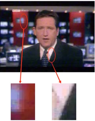
After the regions are detected in the frame, we measure saliency of each region and decide if the region is a salient object or not. To measure saliency we are trying to find the regions in the focus of the camera. Since the focus adjustment will be made to have the images of the salient objects unblurred, the objects in focus should be the objects we are looking for. Our observations tell that in focus objects have sharper edges than out of focus objects (see Figure 3.5). Since our target application is news domain, most of the objects are composed of more than one color. If the object is out of focus, the colors will be blurred, and if the object is in focus, the colors will be distinguishable. Same colors will have less variance when blurred. Thus we employ a variance calculator to measure the saliency.
We assume no salient objects have their size less than 1000 pixels, which is a reasonable assumption considering 1000 pixels approximately cover about
CHAPTER 3. SYSTEM OVERVIEW 24
Figure 3.5: Example of focus effecting edge sharpness.
1/200th area of the screen. For any region, whose size is over 1000 pixels, we calculate the variance over the pixel colors. We calculate variances of the three color channels (red, green and blue) separately, and take the minimum of these values as the representative variance, and use it in the saliency measure. Selecting the minimum helps us to avoid misguiding values to occur where the color change is high. The actual saliency is calculated by scaling the variance to the highest possible variance of the same channel. Highest possible variance is the variance of a pixel group that consists only of an equal mixture of maximum value and minimum value of the group. The maximum possible variance can be calculated using the following equation.
σmax =
valuemax− valuemin
2
!2
After finding the actual saliency of each region, we find the maximum saliency and mark all regions with a saliency greater a threshold.
CHAPTER 3. SYSTEM OVERVIEW 25
3.3
Object Tracking
Our object tracking mechanism matches the detected possible objects between the frames. Every object being tracked has the following attributes:
• Location: x and y coordinates in the frame.
• Speed: x and y displacement expectation for the next frame • Aspect ratio: width / height of the MBR of the object • Size: width * height of the MBR of the object
• Consistency: The number of frames, this object is detected in the current shot
The similarity of the objects is based on their location and shape. Location similarity (sl)is calculated based on the difference of expected coordinates of the
tracked object T , and the coordinates of the detected object D, with the following equation:
sl= max(0, 1 −
kT − Dk 100 )
Shape similarity (ss)has two components, size and aspect ratio similarity (sa),
which are calculated as follows: ssize = 1 − kT.size − D.sizek T.size sa= 1 − kT.aspect − D.aspectk T.aspect
We multiply these two probabilities to obtain shape as follows: ss = ssize× sa
Finally, we derive overall similarity (sf)by combining shape and location
similar-ities as follows:
sf = 1 − s
(1 − sl)2+ (1 − ss)2
CHAPTER 3. SYSTEM OVERVIEW 26
In our experiments we have deduced that if the overall similarity is greater than 0.8, then the detected object D can be the same object as the tracked object T in the current frame. Among candidates, the object with the highest probability will be marked as continuation of the tracked object. If an object fails to get 0.8 probability with any tracked object, then it is referred as a new object to track.
3.4
User Interaction and Knowledge-base
Con-struction
Except for the naming of the objects, our tool can work in a fully automatic mode. However, the quality of the video and the scene complexity may result in very low quality object detection. Under these circumstances, the user should specify the objects manually. As a result of the codec chain system, automatic and manual detection of objects can work independently.
Video processing can be completed in 2 or 3 passes depending on the require-ments of the user and video. In the first pass, we extract the detected objects, and dump object information to an output file, which has an extension “out”. The first pass is fully automatic and does not require any user interaction after the initial setup. The user just needs to ensure the video is processed with the proper set of codecs, depending on the noise level and complexity of the scenes. Optional second pass is required if the user wants to specify objects that could not be detected by the system. The users can specify MBR’s of the objects that they want to be tracked in the scene using the mouse. The objects tracked in this pass are also added to the output file. In the next pass, the system asks the name of each tracked object to the user. The user can delete incorrect objects (false positives) and give proper names for the objects. Objects that are not deleted, i.e. given proper names, are stored in an object information file, which has an extension “obj”. After all the passes complete, another small program is executed to convert object information file to a knowledge-base file. This pro-gram is also responsible for correcting the output. For example, if an object with name “Speaker” appears between frames 50 and 100, and an object with the same
CHAPTER 3. SYSTEM OVERVIEW 27
name appears between frames 105 and 140, these two are assumed to be the same object if their MBR’s are also similar. In such a case, the knowledge-base file will contain entry Speaker appearing between frames 50 and 140. Another type of correction is expanding temporal object region to the shot boundaries. If the object appears within the first five frames of a shot, it is assumed to be present at the beginning of the shot.
Chapter 4
Performance Results
In this chapter we present performance results of our program, and discuss the advantages and disadvantages of our system based on these results. The results are obtained from the application of the algorithms to our two test videos. Video 1 has a higher noise ratio than Video 2. Both of the videos have a frame rate of 12 frames per second, and they are captured from live TV broadcast.
4.1
Cut Detection
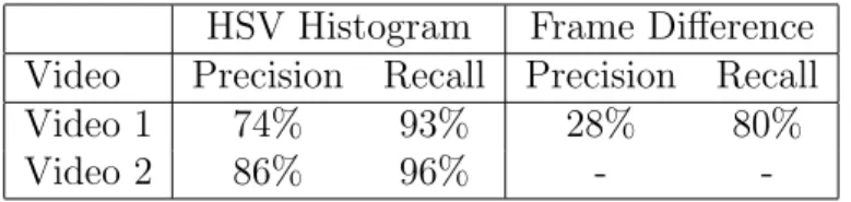
We have tested out cut detection mechanisms on our test videos. The low frame rate of the videos adversely affects the cut detection, as cut detection robust-ness depends on the inter frame changes of representative attributes. We have counted the number of found shot boundaries, missed shot boundaries and false positives(i.e. frames where no shot boundary occurs, however, our detector marks a shot boundary). Based on these values, we have calculated precision and recall as follows: precision= f ound f ound+ f alse recall = f ound f ound+ missed 28
CHAPTER 4. PERFORMANCE RESULTS 29
HSV Histogram Frame Difference Video Precision Recall Precision Recall Video 1 74% 93% 28% 80% Video 2 86% 96% -
-Table 4.1: Cut detection results.
Results from HSV histogram and frame difference based shot boundary de-tection are displayed in Table 4.1. HSV histogram based cut dede-tection performs much better than difference based cut detection. Difference based cut detection does fail in video 2, due to highly dynamic scenes. Since the method relies on average of all frames in a shot, one missed shot makes shot boundary detection almost impossible.
HSV histogram difference based cut detection can handle most general cases. In photograph flashes, since it does not consider non-representative values, mostly it does not return a false positive. However, if the flash is strong, then the number of representative values greatly reduces, and a false positive generally occurs. Another source of false positives is the objects that clutter all objects in the scene. This case mostly happens when a person walks in front of the camera in a crowded scene. Since the color distribution of the scene changes quickly, this cluttering cases cause a false positive. HSV histogram difference also fails to find shot boundaries where the objects in the scene change, but the color distribution is similar.
4.2
Object Detection
Object detection accuracy is based on the complexity of the scene. Simple scenes, objects are detected with almost perfect accuracy. As the number of pixel regions increases, the program fails to find regions that form an object. The detection also fails when the video noise is high. High noise causes pixel colors to change, and these pixels form a region. Mostly this region has parts from two different objects, or an object and the background. As the basic assumption that each region will belong to either exactly one object or background, the region identification mechanism dramatically fails. To correct the problem we employed the noise
CHAPTER 4. PERFORMANCE RESULTS 30
removal codec, which have improved the results to a great extend.
Another problem with object detection is saliency. In some videos, the channel logo and any other text are returned as salient objects, because their sharpness is quite high. In fact, it is almost two times higher than any other object in the scene. Due to our adaptive saliency threshold, these logos and texts prevent salient objects to be detected. To compensate this, we needed to decrease the threshold, which in turn increased false positive detections.
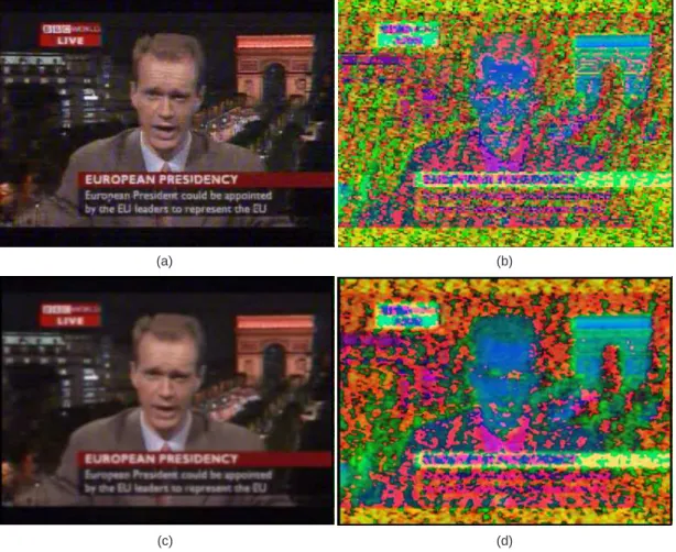
In a shot of Video 1, a frame of which is displayed in Figure 4.1, our program detects anchorman in 36 of 60 frames in the shot, resulting in a 60% detection rate. The channel logo is also detected in 36 of 60 frames in the shot. There were also 25 false positives, 14 of which are detected for more than 5 frames and one of which is detected more than 10 frames. The detection rate is quite low and false positive count is high, as the video noise is very high. Figure 4.1 demonstrates the noise before and after noise reduction.
Object detection results for Video 2 are substantially better, due to low noise. In a shot of Video 2, a frame of which is shown in Figure 4.2, our program detects anchorwoman in 244 of 258 frames in the shot, resulting in a 95% detection rate. The body of the woman is detected seperately with 91% detection rate. There are 18 false positives, 10 of which are detected for more than 5 frames, and 7 of which are detected for more than 10 frames. Clearly, the noise level affects the object detection quality drastically.
4.3
Object Tracking
The quality of the tracking is based on the quality of the object detection. When-ever the objects are detected correctly and consistently, tracker accurately tracks objects in the scene. The only tracking problem we have encountered in our ex-periments involve objects that are mis-detected. In case of two objects of about the same shape moving toward each other the tracker may fail to correctly label objects if they cannot be detected at the time of contact. Although occlusions do
CHAPTER 4. PERFORMANCE RESULTS 31
(a) (b)
(d) (c)
Figure 4.1: An example frame from Video 1. The original frame (a); The HSV visualization of the original frame (b); The original frame after noise reduction (c); The HSV representation of the frame after noise reduction (d).
CHAPTER 4. PERFORMANCE RESULTS 32
(a) (b)
Figure 4.2: An example frame from Video 2. The original frame (a); The HSV representation of the frame (b).
not happen often in news videos, we suggest possible solutions for this problem in the next chapter.
4.4
Extraction Time
Our aim was to reduce the time required to process a video, rather than improving performance of individual parts. To measure any improvement, we have compared time and effort required to process videos for fact extraction. We have measured the time requirements for automatic extraction, where no user interaction occurs, and complete manual extraction, where user specifies all objects manually for our system to track. We have estimated the time required for the old method, fact-extractor tool. The results of our experiments can be seen in Table 4.2. For comparison purposes, we have considered the worst case scenario where every frame should be processed. However, many actual scenarios contain shots that may be discarded because they contain no objects of importance.
According to results, video 1 has a very long automatic extraction time. This is mostly because of the extra codecs we needed to use to reduce the video noise. Since the automatic extraction process does not require human interaction, the
CHAPTER 4. PERFORMANCE RESULTS 33
Video Video Run-length Old Method Automatic Manual Video 1 1m 13s 2h 26m 4h 42m 29m Video 2 11m 37s 22h 42m 10h 47m 4h 20m
Table 4.2: Object extraction time comparison table.
time is not much of a problem. The user interaction is required only for manual object extraction and object naming. Manual object extraction is only necessary for the objects that the automatic extraction fails to find. Even if the user wants to extract all objects manually, both results indicate that the user time required for the extraction is reduced to one fifth. Naming process only lasts as long as the original video, since all the user has to do is to watch the video, and type in the names of the objects.
Chapter 5
Conclusion and Future Work
In this thesis, we have developed the Automatic Object Extractor tool, which is a part of BilVideo video database management system. Our tool tries to extract objects from a video, in hopes of speeding up the processing of videos for spatio-temporal querying. Although the accuracy of the individual parts are not monumental, use of our system greatly reduces user time and effort for video processing. Below we list improvements that can be implemented to increase accuracy and efficiency of the system.
5.1
Possible Improvements
There are numerous possible improvements on the currently applied methods and algorithms. Some of these improvements are explained below, and are categorized depending on the improved component.
5.1.1
Cut Detection
Cut detection system can be improved by dividing the frame into several regions, and comparing the histograms belonging to these regions between frames. This
CHAPTER 5. CONCLUSION AND FUTURE WORK 35
will provide some location information about the composition of the frame, and will improve the results of the cut detection. Better cut detection will help improving the tracking mechanism, since reduced number of false positives and missed shot boundaries will result in less disrupted trajectories.
5.1.2
Object Detection
Object detection is the most crucial part of the system, and the overall perfor-mance depends heavily on it. It can be improved by improving its three integral parts: pixel grouping, region identification and saliency measure. Pixel grouping is currently based on just the color of pixels. The major improvement would be to include location information when grouping the pixels in the frame. This would theoretically allow shape based grouping of the pixels, and help in region iden-tification. Region identification can be improved by including edge and saliency information when deciding the patches that needs to be merged. This would def-initely increase the accuracy of the object bounds since it uses more descriptive features of the objects. Saliency measure can be improved using statistical meth-ods on region features, which include but not limited to color distribution, edge distribution and region location. In the current system, these stages are com-pleted sequentially, an error from one of the stages propagates into next stages. To prevent this, all these three stages can be merged. Since the data in these stages can benefit from each other, the results would improve.
5.1.3
Object Tracking
The accuracy of the tracker mainly lies on the accuracy of the object detection. Any improvement on object detection mechanisms will also improve the results of the tracker. Estimation of speed algorithm can be improved by considering accelerations and multiple frame averages. The main improvement possible on tracker is adding pixel based matching and tracking of objects, which requires the tracker to be integrated to the object detector. The tracker should also be improved to handle occlusions better. To this end, it is possible to implement a
CHAPTER 5. CONCLUSION AND FUTURE WORK 36
merge-split based tracking system as in [14].
5.2
Future Add-Ons
Due to its scalability, it is possible to improve our system with extra features to reduce the necessary user time for video processing even more. One of the imme-diate improvements is to add a batch processing mode to handle large amounts of videos in a specified location. Thus, the user will not need to load each video separately. One interesting add on could be developing an object recognition method to identify if a detected object is the same object as a named object in a previous shot. In this case, user would only need to specify name of an ob-ject once in whole video, rather than once in every shot. This method can be augmented with a database which stores the features of previously detected and named objects. Whenever an object is detected it can be automatically named if the object can be found in the database. So the objects can be recognized across the videos.
Bibliography
[1] J. J. Ashley, R. Barber, M. D. Flickner, J. L. Hafner, D. Lee, W. Niblack, and D. Petkovic. Automatic and semiautomatic methods for image annotation and retrieval in query by image content (QBIC). In Proc. SPIE Storage and Retrieval for Image and Video Databases III, Wayne Niblack; Ramesh C. Jain; Eds., volume 2420, pages 24–35, Mar. 1995.
[2] S. Belongie, C. Carson, H. Greenspan, and J. Malik. Color- and texture-based image segmentation using EM and its application to content-texture-based image retrieval. In Proceedings of the Sixth International Conference on Computer Vision, 1998.
[3] J. S. Boreczky and L. A. Rowe. Comparison of video shot boundary detec-tion techniques. In Proc. SPIE Storage and Retrieval for Image and Video Databases IV, volume 2670, pages 170–179, San Jose, California, USA, 1996. [4] A. Cavallaro, O. Steiger, and T. Ebrahimi. Multiple video object tracking in complex scenes. In MULTIMEDIA ’02: Proceedings of the Tenth ACM International Conference on Multimedia, pages 523–532, New York, NY, USA, 2002. ACM Press.
[5] S.-F. Chang, W. Chen, H. J. Meng, H. Sundaram, and D. Zhong. Videoq: An automated content based video search system using visual cues. In ACM Multimedia, pages 313–324, 1997.
[6] S. M. Desa and Q. A. Salih. Image subtraction for real time moving object extraction. In International Conference on Computer Graphics, Imaging and Visualization (CGIV’04), pages 41–45, 2004.
BIBLIOGRAPHY 38
[7] M. E. Donderler, E. Saykol, O. Ulusoy, and U. Gudukbay. Bilvideo: A video database management system. IEEE Multimedia, 10(1):66–70, Janu-ary/March 2002.
[8] M. E. Donderler, O. Ulusoy, and U. Gudukbay. A rule-based approach to represent spatio-temporal relations in video data. In International Con-ference on Advances in Information Systems (ADVIS’2000), volume 1909, pages 409–418. Springer-Verlag, October 2000.
[9] R. O. Duda, P. E. Hart, and D. G. Stork. Pattern Classification. Wiley-Interscience, Second edition, 2000.
[10] M. Flickner, H. Sawhney, W. Niblack, J. Ashley, Q. Huang, B. Dom, M. Gorkani, J. Hafner, D. Lee, D. Petkovic, D. Steele, and P. Yanker. Query by Image and Video Content: The QBIC System. Computer, 28(9):23–32, 1995.
[11] D. A. Forsyth and J. Ponce. Computer Vision: a Modern Approach. Prentice Hall, International edition, January, 2003.
[12] C. Gu and M.-C. Lee. Semiautomatic segmentation and tracking of seman-tic video objects. IEEE Transactions on Circuits and Systems for Video Technology, 8(5):572–584, September 1998.
[13] S. Han, G. W. Humpreys, and L. Chen. Uniform connectedness and classical gestalt principles of perceptual grouping. Percept Psychophys, 61(4):661–674, 1999.
[14] C. Kim and J.-N. Hwang. Fast and automatic video object segmentation and tracking for content-based applications. IEEE Trans. Circuits Syst. Video Techn., 12(2):122–129, 2002.
[15] D. Koller, K. Daniilidis, and H. Nagel. Model-based object tracking in monocular image sequences of road traffic scenes. International Journal of Computer Vision, 10(3):257–281, June 1993.
[16] L. Li, W. Huang, I. Y. H. Gu, and Q. Tian. Foreground object detection from videos containing complex background. In MULTIMEDIA ’03: Proceedings
BIBLIOGRAPHY 39
of the Eleventh ACM International Conference on Multimedia, pages 2–10, New York, NY, USA, 2003. ACM Press.
[17] Y.-T. Lin, Y.-K. Chen, and S. Y. Kung. A principal component clustering approach to object-oriented motion segmentation and estimation. Journal of VLSI Signal Processing, 17(2-3):163–187, 1997.
[18] W. Y. Ma and B. S. Manjunath. Edgeflow: A technique for boundary detec-tion and segmentadetec-tion. IEEE Transacdetec-tions on Image Processing, 9(8):1375– 1388, Aug 2000.
[19] S. Mahamud, K. K. Thornber, and L. R. Williams. Segmentation of salient closed contours from real images. In ICCV ’99: Proceedings of the Inter-national Conference on Computer Vision-Volume 2, page 891, Washington, DC, USA, 1999. IEEE Computer Society.
[20] S. Marcus and V. S. Subrahmanian. Foundations of multimedia database systems. Journal of the ACM, 43(3):474–523, 1996.
[21] O. Marques and N. Barman. Semi-automatic semantic annotation of images using machine learning techniques. In Lecture Notes in Computer Science, volume 2870, pages 550–565. Springer-Verlag, January, 2003.
[22] F. P. Preparata and M. I. Shamos. Computational Geometry: An Intro-duction. Springer-Verlag, corrected and expanded second printing edition, 1988.
[23] R. Rosales and S. Sclaroff. Improved tracking of multiple humans with trajec-tory prediction and occlusion modeling. Technical Report 1998-007, Boston University, February 1998.
[24] E. Saykol. Web-based user interface for query specification in a video data-base system. Master’s thesis, Bilkent University, September, 2001.
[25] E. Saykol, U. Gudukbay, and O. Ulusoy. A semi-automatic object extraction tool for querying in multimedia databases. In In Proceedings of 7th Work-shop on Multimedia Information Systems MIS’01, pages 11–20, Capri, Italy, November 2001.
BIBLIOGRAPHY 40
[26] J. Shi and J. Malik. Normalized cuts and image segmentation. IEEE Trans-actions on Pattern Analysis and Machine Intelligence, 22(8):888–905, 2000. [27] J. R. Smith and S.-F. Chang. Visualseek: A fully automated content-based
image query system. In ACM Multimedia, pages 87–98, 1996.
[28] L.-Q. Xu, J. L. Landabaso, and B. Lei. Segmentation and tracking of mul-tiple moving objects for intelligent video analysis. BT Technology Journal, 22(3):140–150, 2004.
![Figure 2.1: Segmentation results obtained by the method proposed by Mahamud et al. [19]](https://thumb-eu.123doks.com/thumbv2/9libnet/5607828.110696/22.892.327.631.165.473/figure-segmentation-results-obtained-method-proposed-mahamud-et.webp)