Modeling and animating personalized faces
Tam metin
Şekil
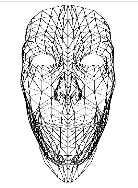
![Figure 3.1: The frontal view of the skull [56].](https://thumb-eu.123doks.com/thumbv2/9libnet/5882460.121458/26.918.218.744.176.784/figure-frontal-view-skull.webp)
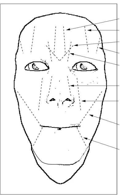
![Figure 3.3: The frontal view of the facial muscle structure [56].](https://thumb-eu.123doks.com/thumbv2/9libnet/5882460.121458/28.918.223.743.131.722/figure-frontal-view-facial-muscle-structure.webp)
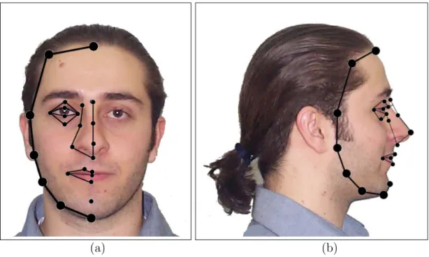
![Figure 4.1: The MPEG-4 Face Definition Parameters [48].](https://thumb-eu.123doks.com/thumbv2/9libnet/5882460.121458/44.918.179.784.135.953/figure-the-mpeg-face-definition-parameters.webp)


Benzer Belgeler
Using the analogy between the SL(2, C) gauge theory of gravitation and the Yang-Mills theory, we propose a model for massive vector bosons.. The model is based on
We present this technique due to the fact that bleeding usually occurs in side-arm graft technique from axillary artery cannulation site during cardiopulmonary bypass
In the networks with DWDM equipments, if different logical links use the same physical resources, the failure of a node or physical link may cause more than one failure in the
In our master production scheduling problem, we use a multi- stage stochastic programming approach and a scenario tree in or- der to handle the uncertainty in demand.. Since
Pilot Yeniden Kullanım Faktörleri Kullanılarak Sabit BS Anten Sayılı, Değişen Kullanıcı Sayılı Büyük Ölçek MIMO Sisteminde Spektrum Verimliliği Pilot yeniden
sayıda Nazım Hikmet'i kapak
In this paper, a new topology employing voltage controlled-voltage sources instead of voltage controlled-current sources in CNNs is introduced and two simple cell macromodels
Bu gün kısa zamanda gerçek olmuş öyle o- lavlar vardır ki, vaktiyle sayın Gürsel bunları söylediği zaman onun uzak görüşünü bu günkü çıplaklığı
