234 ICTON 2001 We.P.5
Simulating a Wavelength-Size
2-D
Lens
with an Accurate Numerical Method
Artem V. Boriskin, Alexander
I.
Nosich, Ayhan Altintas*
Institute of Radiophysics and Electronicsof the National Academy of Sciences of Ukraine, Kharkov 61 085, Ukraine
*
Bilkent University,O6533 Ankara, Turkeye-mail: a-boriskin@yahoo. com
ABSTRACT
The effect of a localized light source directivity improvement due to an arbitrarily shaped dielectric cylinder taken as a 2-D model of a dielectric lens is studied. The source is simulated by the field of a Complex Source- Point (CSP). An efficient algorithm for the solution of 2D problem of wave scattering by a smooth dielectric cylinder is developed, based on the concept of analytical regularization. Basic properties of the algorithm are studied. Numerical results for the accuracy of the algorithm and sample far-field characteristics such as total radiated power, directivity and radiation pattems for various lens parameters are presented.
INTRODUCTION
In the optical and microwave ranges, dielectric lenses and rods are frequently used to focus the radiation or improve its directive character. However, analysis and design of lenses frequently involves
a
number of high- frequency approximations neglecting the lens edges and not taking a full iiccount of all the interactions between different parts of the scattering objects [ 13. If done numerically, it is often based on the discretizations having unclear and uncontrollable accuracy. Another commonly faced drawback which may spoil the wavelength-scale lens analysis is due to modeling of the incident field as a dipole field [2] or a Gaussian beam [3]. This is because the former field has a fixed shape, and the latter does not satisfy the Helmholtz equation. Therefore, there isa need in developing a more adequate simulation technique able to serve a!; a promising CAD tool.
MATHEMATICAL MODEL
discussed, as shown in Fig. 1.
The 2-D model of a dielectric lens scattering is Lens: The scatterer is taken as a homogeneous isotropic section [4] that simulates a rectangle with rounded edges.
The curve L bounding the lens cross-section is determined by the following equation:
dielectric cylinder with a so-called "super-elliptic" cross- X
*
[x/la]2"
+
Iy/a]2" = 1,
0 < v<
a, (1) Fig. 1 Scattering geometry and notations.Dot:i and cuny line denote branch points and biwnch cut in the real space due to CSP. where I is the axial ratio and parameter v determines the
supper-ellipse comer rounding. The greater the value of the
parameter v , the closer the cross-section contour to a rectangle ( v =1 corresponds to an ellipse), however for all v>1/2 it is a twice-differentiable curve.
Source: The incident field is generated by a CSP line source located at rCs
.
The main advantages of the CSP fieldU , ( r ) = H i ' ) (klr
-
r,l) (2)are that it is an exact solution of the Helmholtz equation with respect to the observation point, and has a variable beam width controlled by parameter kb [5]. Here k is the free-space wavenumber, and the complex source position vector is
This work was supported by The IEEE MTTSociety and by The TUBITAK (Scientrfic and Technical Research Council of Turkey) in the form offellowships to the first author. The aid ofDr. S. V. Boriskina in developing the computer code is acknowledged with gratitude.
ICTON 200 1 235 We.P.5
Parameters b and
p
can be associated with the width and orientation angle of a light-emitting aperture simulated by a CSP. Note that the CSP excitation depicted in Fig. 1 imply thatp
= n.
Hence, the branch points of U. in the real space are located at (xo , y o f b ) , with yo = 0.Basic
IEs
a n d analytical regularization: The total field has to satisfy the Helmholtz equation with the coefficients k and k , = k& inside and outside the lens, respectively. After splitting out the incident CSP field, it is presented in terms of the single-layer potentials with the density functions to be determined:where the kernels are the Green’s finctions of the free space and uniform media of relative permittivity E ,
respectively:
( 5 )
i
4 4
Go(r,rs) = LHo (klr
-
r,l), G, (r, r,) = - H o (klr-
rsl)and H , is the Hankel function of the first kind.
By applying the boundary conditions, a set of singular integral equations (IEs) is obtained. Extraction and analytical inversion of the singular parts of the IEs are done by adding and subtracting the canonical-shape operators with kernels :o(e) =
-
H , (2k{e)uSinI(t-
t s ) / 2 / ) , and their normal derivatives, respectively, and byusing a Galerkin scheme with angular exponents as global basis functions. This results in a coupled pair of infinite-matrix equations having favorable features:
i
4
-
where the matrix elements A,, , B,, , C,, , D,, and U,, U, are obtained as Fourier-expansion coefficients,
with integrands given by the smooth functions. The latter are the differences between (5) on L and on the canonical-shape contour, i.e. a circle of radius U. The coefficient a is 1 or E for E- or H- polarization, respectively. Equation (6) can be easily transformed to a classical block-type Fredholm second-kind matrix equation.
Such a regularization guarantees point-wise convergence of the numerical solution, i.e., a possibility to minimize the error to machine precision by solving progressively greater matrices. The rate of convergence of the algorithm can be estimated
by
plotting the normalized computational error, e(NK), in the sense of theI,’
norm, versus the matrix truncation number NK:
where pfK, v/fK are the expansion coefficients computed from the matrix equation with each block truncated after NK equations. Details of the algorithm properties can be found in [6].
In application to dielectric scatterers, this approach is also free from the heavy inaccuracies near to natural resonances that are intrinsic for conventional numerical approximations [7].
Field characteristics: As the far-field characteristics are of interest, the large-r approximation is used. This enables one to replace the Hankel finctions with its asymptotic and to reduce the first integral of (4) to
where @ ( t ) is the far-field radiation pattern.
radius r
--+
03 and can be presented as a series in the following way:We.P.5 236 ICTON 200 1
4 -
3 -
2 -
where Y,,," are the Fourier-expansion coefficients, with the integrand given by the corresponding factor in (S), and
a. is Zo or Z i ' , in the case of the E- and H- polarization, respectively, Z, =
(~~/,u~)1'~
is the free space impedance.Based on the series representation, main-beam directivity is determined as:
Note that numerical results for the total radiated power and directivity should be compared to the same values
for a CSP located in free space:
where I, is the modified Bessel function.
NUMERICAL RESULTS
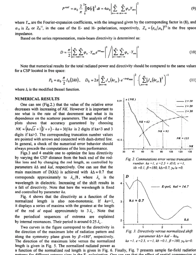
One can see (Fig.2.) that the value of the relative error decreases with increasing of
NK.
However it is important to see what is the rate of that decrement and what is its dependence on the scatterer parameters. The analysis of the plots shows that accuracy guaranteed by choosing NK c (ka&+
l k+
Y ) - ka+
30/ka is 2 digits if ka<3 and 3digits if ka>3. The corresponding truncation number values are pointed with arrows and connected with dash-dotted line. In general, a check of the numerical error behavior should always precede the computations of the lens performance.
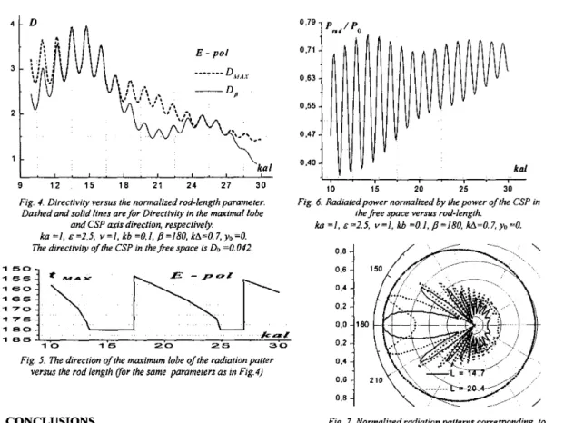
Figs.3 and 4 enable one to optimize the lens directivity by varying the CSP distance from the back end of the rod- like lens and by changing the rod length, as controlled by
parameters
kA
andkal,
respectively. One can see that the main maximum ofD(kA)
is achieved with kAo0.7 that corresponds approximately to & / 8 , whereA,
is the wavelengthin
dielectric. Increasing of the shift results in a fall of directivity. Note that here the wavelength is fixed and controlled by parameter ka.Fig.
4
shows that the directivity as a function of the normalized length is also non-monotonic. If ka= 1, it displays a series of maxima with the greatest at the length of the rod al equal approximately to 3 4 . Note that the periodical sequences of extrema are explained by internal resonances. Their period is around 0.25 l e .Two curves in the figure correspond to the directivity in the direction of the maximum lobe of radiation pattern and along the symmetry plane given by
p
=1 80°, respectively. The direction of the maximum lobe versus the normalizedI \n=-w 0.01 10 20
---
*.--..______
I = 30-..
1 , . -: -t '--\..
NK = 122 1 E-3 8 i i N K t 30 45 60 75 90 105 120 135Fig. 2. Commutations error versus truncation
number. ka = I , E =2.5 f iO.0, v =1,
kb =O. I. /=180. kA=O. 7, yo/a =O.
-
E-pol, k a l = 14.7;
1 2i
Fig. 3. Directivity versus normalized shqt ka = I j . ~ = 2 . 5 . v = l , kb =O.I, p=180, yo/a=O.
parameter kA= kal -
length is given in Fig. 5 . The normalized radiated power as
a function of the normalized rod length is given in Fig. 6. Finally, Fig. 7 presents sample far-field radiation patterns for different antenna sizes in the E- polarization. One can see that the effect of spatial compression of the originally almost omnidirectional radiation really takes place. Besides, the splitting of the main-lobe is also well seen that makes intuitive consideration "the longer rod, the better" invalid and calls for a full-wave analysis.
As a resonant nature of the effects is clearly seen a further research is required and will be done by the presented approach.
ICTON 2001 237 We.P.5 n n 9 kal 4 . I . I . I . I . I . I 1 2 1 5 1 8 2 1 2 4 2 7 3 0 i 0.71
-
0.63-
0,55-
0.47-
0,40-
kal I . , . , 10 15 20 25 30Fig. 4. Directivity versus the normalized rod-length parameter. Dashed and solid lines are for Directiviv in the maximal lobe
Fig. 6. Radiatedpower normalized by the power of the CSP in the free space versus rod-length.
and CSP axis direction, respectively. k a = I , &=2.S, v = I , kb=O.l,p=180, kA=O.7,yo=O.
ka = I . ~ = 2 . 5 . ~ ‘ 1 . kb =0.1, p = l 8 0 , kA=0.7,yo=O. 1 5 0 1 5 5 1 6 0 1 6 5 1 7 0 1 7 5 I a o 1 6 5
The directivity of the CSP in the free space is DO =0.042.
j
1 0 r 1 5 i 2 0 a :Fig. 5. The direction of the maximum lobe of the radiation patter versus the rod length Vor the same parameters as in Fig.4)
0.8
1
0.4 o’6‘1
0.0 18( 0.2 o‘2!CONCLUSIONS Fig. 7. Normalized radiation patterns corresponding to
the maximum and minimum of the directiviv in Fig. 4. Dash-
ka = I . ~ z 2 . S . v = l . kb =0.1. 0=180. kAz0.7. vn=O.
An efficient and accurate based On
the analytical regularization, to the 2D problem of the is for the . . of the Same C s p . , in thefree space,
.-
wave scattering by an arbitrary shaped smooth dielectriccylinder has been used to analyze the dielectric rod-like lens performance. Though, as it is shown, the algorithm can generate data with up to digital precision, a uniform 2-digit accuracy was kept for numerical results. It has been demonstrated that placing a light-emitting source inside a dielectric rod-like lens leads to a significant improvement of directivity. Also the importance of the right choice of CSP location with respect to the back end of the rod and the rod length has been shown. The given sample far-field radiation patterns demonstrate the effect of focusing if these parameters are chosen properly.
The presented approach can be easily modified to cover the case of a beam source located outside the dielectric lens. Such a geometry can be used to simulate an external laser-beam input to an optical lens or a section of optical fiber.
REFERENCES [I] [2] [3] [4] [5] [6] [7]
C. Salema, C. A. Fernandes, R.K. Jha, Solid Dielectric Horn Antennas, Boston: Artech House, 1998.
H. Mieras, ‘Radiation pattern computation of a spherical lens using Mie series’, IEEE Trans. on Anfennus Propagat., vol. AP-30, no. 6, pp. 1221-1224, 1982.
E. E. M. Khaled, S. C. Hill, P. W. Barber, ‘Scattered and internal intensity of a sphere illuminated with a Gaussian beam’, IEEE Trans. AntennasPropagaf., vol. 4, no. 3, pp. 1221-1224, 1999.
M.Gardner, ‘Mathematical games’, Scienfific American, vol. 213, no. 3, pp. 222-232, 1965.
L. B. Felsen, ‘Complex-point source solutions of the field equations and their relation to the propagation and scattering
of the Gaussian beams’, Symp. Mathem., vol. 18, pp. 39-56, 1975.
S.V.Boriskina, A.I. Nosich, ‘Fast and accurate in resonances solution to the scattering by arbitrary dielectric cylinders based on the canonical-shape inversion’, IEEE Trans. Anfennus Propagaf., 2001, submitted.
G.L. Hower, et a l . , ’Inaccuracies in numerical calculations of scattering near natural frequencies of penetrable objects’,