A. Moreira et al. (Eds.): MODELS 2013, LNCS 8107, pp. 757–773, 2013. © Springer-Verlag Berlin Heidelberg 2013
Model-Driven Approach
for Supporting the Mapping of Parallel Algorithms
to Parallel Computing Platforms
Ethem Arkın1, Bedir Tekinerdogan2,and Kayhan M. İmre1
1
HacettepeUniversity, Dept. of Computer Engineering, Ankara, Turkey {earkin,ki}@hacettepe.edu.tr
2
BilkentUniversity, Dept. of Computer Engineering, Ankara, Turkey [email protected]
Abstract. The trend from single processor to parallel computer architectures has increased the importance of parallel computing. To support parallel compu-ting it is important to map parallel algorithms to a compucompu-ting platform that consists of multiple parallel processing nodes. In general different alternative mappings can be defined that perform differently with respect to the quality re-quirements for power consumption, efficiency and memory usage. The mapping process can be carried out manually for platforms with a limited number of pro-cessing nodes. However, for exascale computing in which hundreds of thou-sands of processing nodes are applied, the mapping process soon becomes in-tractable. To assist the parallel computing engineer we provide a model-driven approach to analyze, model, and select feasible mappings. We describe the de-veloped toolset that implements the corresponding approach together with the required metamodels and model transformations. We illustrate our approach for the well-known complete exchange algorithm in parallel computing.
Keywords: Model Driven Software Development, Parallel Computing, High Performance Computing, Domain Specific Language, Tool Support.
1
Introduction
The famous Moore’s law states that the number of transistors on integrated circuits and likewise the performance of processors doubles approximately every eighteen months [1]. Since the introduction of the law in 1965, the law seems to have quite accurately described and predicted the developments of the processing power of com-ponents in the semiconductor industry [2]. Although Moore’s law is still in effect, currently it is recognized that increasing the processing power of a single processor has reached the physical limitations [3]. Hence, to increase the performance the cur-rent trend is towards applying parallel computing on multiple nodes. Here, unlike serial computing in which instructions are executed serially, multiple processing ele-ments are used to execute the program instructions simultaneously.
To benefit from the parallel computing power usually parallel algorithms are de-fined that can be executed simultaneously on multiple nodes. As such, increasing the
processing nodes will increase the performance of the parallel programs [4][5][6]. An important challenge in this context is the mapping of parallel algorithms on a compu-ting platform that consists of multiple parallel processing nodes. In general a parallel algorithm can be mapped in different alternative ways to the processing nodes. Fur-ther, each mapping alternative will perform differently with respect to the quality requirements for speedup, efficiency and memory usage that are important in parallel computing [7]. The mapping process can be carried out manually for platforms with a limited number of processing nodes. However, over the last decade the number of processing nodes has increased dramatically to tens and hundreds of thousands of nodes providing processing performance from petascale to exascale levels [8]. As a consequence selecting a feasible mapping of parallel algorithm to computing plat-forms has become intractable for the human parallel computing engineer. Once the feasible mapping is selected the parallel algorithm needs to be transformed to the target parallel computing platform such as MPI, OpenMP, MPL, and CILK [15]. Due to the complexity and size of the parallel computing platform usually it is not easy to implement the algorithm manually on these platforms based on the selected mapping. Moreover, in case of requirements for changing the implementation platform porting the system to a new platform will be cumbersome.
In this paper we provide a model-driven approach to analyze, model, and select feasible mappings of parallel algorithms to a parallel computing platform. In the ap-proach we provide the steps for defining models of the computing platform and the parallel algorithm. Based on the analysis of the algorithm and the computing platform feasible mappings are generated. The approach is supported by a corresponding tool-set that builds on a predefined metamodel. Using model-to-model and model-to-text transformations we provide a solution to the code generation and portability prob-lems. We provide an evaluation of our approach for the well-known complete ex-change algorithm in parallel computing. The evaluation considers both the time to generate the alternative mappings, and the feasibility of the generated alternative on a real computing platform with respect to speedup and efficiency performance quality attributes.
The remainder of the paper is organized as follows. In section 2, we describe the problem statement. Section 3 presents the metamodel which is used by the approach that is described in section 4. Section 5 presents the tool that implements the ap-proach. In section 6 we describe the evaluation of the apap-proach. Section 7 presents the related work and finally we conclude the paper in section 8.
2
Problem Statement
In this section we will describe the problem statement in more detail by considering the mapping of the complete exchange parallel algorithm to a parallel computing platform. Fig. 1 shows the complete exchange algorithm which purpose is to collect all data from all nodes and to distribute data to all nodes [9][10][11]. This algorithm is a commonly used parallel algorithm that is often used as part of a bigger parallel algo-rithm. For instance, in simulation of molecular dynamics, the data of all particles are exchanged with each other to calculate some values like affinity between molecules. The complete exchange algorithm refers to nodes of a computing platform on which
the algorithm will run. Hereby, some nodes are selected as dominating nodes [12] that collect data, exchange data with each other and distribute the data to the other nodes.
Procedure Complete-Exchange:
For i=1 to n-1
Collect data to the dominating nodes from the dominated nodes
Endfor
For i=n-1 downto 1
Exchange the selected data between dominating nodes
Distribute data from dominating nodes to the dominated nodes
Endfor
Fig. 1. Pseudo code for Complete Exchange Algorithm
The algorithm is mapped to a computation platform that is defined as a configura-tion of nodes. We distinguish among the physical configuraconfigura-tion and logical configu-ration. The physical configuration defines the actual physical configuration of the system with the physical communication links among the processing units. We as-sume a distributed memory model in which each node has its own memory unit. The logical configuration is a view of the physical configuration that defines the logical communication structure among the physical nodes. Typically, for the same physical configuration we can have many different logical configurations. An example of a physical configuration and its logical configurations is shown in Fig. 2.
Fig. 2. Physical configuration of a topology (left) with two different logical configurations (middle and right)
Given a parallel algorithm like the complete exchange algorithm, it is important to define a feasible mapping of the algorithm steps to the logical configuration. The feasibility of a mapping is defined by the extent to which it supports the performance quality attributes of speedup with respect to serial computing and efficiency [7]. Speedup Sp is defined by the following formula:
ܵൌ்்ೞ
(1) where Ts is the execution time of the serial algorithm.
Tp is the execution time of the parallel algorithm with p processors.
Efficiency metric defines how well the processors are utilized in executing the al-gorithm. The formula for Efficiency Ep is as follows:
ܧൌ ௌ
(2) where Sp is the speed up as defined in equation (1) above and p is the number of processors.
To measure speedup and efficiency the following metrics are applied:
• Number of Cores Used- the number of cores that are used in the computing plat-form for executing the algorithm.
• Port Count Used - the total number of ports of all cores that are used in the com-munication among the cores.
• Communication Length - the total number of communication links among cores that are needed to realize the execution of the algorithm.
To define a feasible mapping of the parallel algorithm to the computing platform the values for the above metrics should be minimized as much as possible to increase speedup and efficiency [7][13][14].
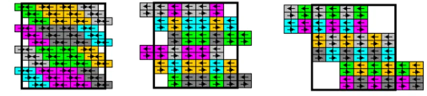
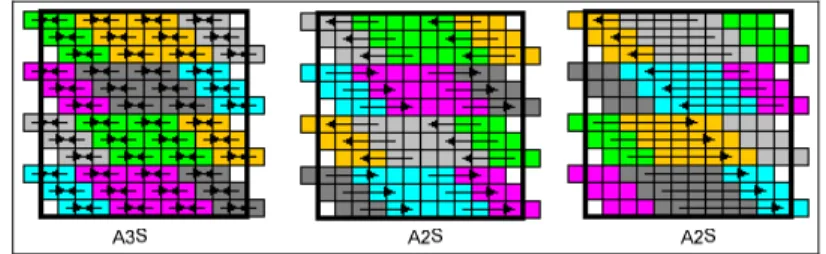
We can now refer to these metrics to discuss the feasibility of the mapping of the al-gorithm to the computing platform. Fig. 3 shows, for example, three different alternative logical configurations of the computing platform to execute the complete exchange algorithm. Each given logical configuration consists of 12x12 cores and represents actu-ally a mapping alternative. The realization of the configurations will differ with respect to the assignment of dominating nodes, the number of cores used, the port count used and the communication length. Hence each logical configuration of the computing plat-form will result in a different speedup and efficiency. Similar to the example logical configurations in Fig. 3 we can identify many other different logical configurations. Selecting the optimal logical configuration with respect to speedup and efficiency is an important challenge for the parallel computing engineer. For smaller computing plat-forms with a limited number of cores the generation and selection of feasible alternative could be done to some extent. However, for larger multicore platform with thousand or tens of thousands of nodes this process becomes intractable.
Fig. 3. Three alternative mapping of complete-exchange algorithm
Here we focus on two important and related problems. First of all, for a given par-allel algorithm and physical configuration we need to define and generate the possible logical configurations and accordingly the mapping alternatives. Secondly, once a feasible mapping alternative is selected the required code for the parallel computing platform needs to be provided to realize the parallel algorithm. Due to the complexity and size of the mapping problem it is not easy to implement the parallel algorithm manually on the parallel computing platforms. Moreover, in case the implementation platform requires changing, porting the system to a new platform will be cumbersome and require considerable time [15]. Obviously, a systematic approach that is supported by tools is necessary to analyze the parallel algorithm, model the logical configuration, select feasible mapping alternatives and generate the code for the com-puting platform.
3
Approach
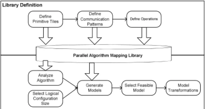
Fig. 4 shows the approach for supporting the mapping of a parallel algorithm for a parallel computing platform, and the generation of the code for the parallel computing platform. The approach consists of two basic sub-processes, library definition and parallel algorithm mapping and model transformations. The main purpose of the library definition sub-process is to define reusable assets including primitive tiles, communication patterns and operation definitions, which will be explained in subse-quent sections. The activities of the library definition process include Define Logical Configuration, Define Communication Patterns and Define Operations. The created reusable assets are stored in the Parallel Algorithm Mapping Library (PAML). The parallel algorithm mapping and model transformations sub-process consists of the activities Analyze Algorithm, Select Logical Configuration Size, Generate Alternative Models, Select Feasible Model, and Model Transformation. This sub-process reuses the PAML assets to analyze the parallel algorithm and generate the alternative map-ping models. The metrics for speedup and efficiency are calculated for each model and a feasible model is selected to be used on transformation and generation of arti-facts. In the following subsections we will describe the metamodel and each step of the approach.
Fig. 4. Approach for mapping of parallel algorithm to parallel computing platforms
3.1 Metamodel
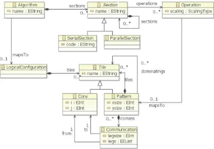
Fig. 5 shows the abstract syntax of the metamodel that is used by the approach in Fig. 4. The metamodel integrates the concepts for parallel algorithms (upper part of figure) with the concepts of parallel computing platforms (lower part of figure). In the metamodel, Algorithm includes one or more Sections. Section can be either Serial Section or Parallel Section and can be composed of other sections. Each section maps to one Operation. Logical Configuration defines the configuration that we have de-fined in section 2, and is composed of a number of Tiles. Tile can be either a (single) Core, or Pattern that represents a composition of tiles. Patterns are shaped by the operations of the sections in the algorithm. Pattern includes also the communication links among the cores.
Fig. 5. Abstract Syntax of the Parallel Algorithm Mapping Metamodel (PAMM)
3.2 Define Primitive Tiles
As shown in Fig. 4, the first step of the definition of the library is the definition of primitive tiles. As stated before, we distinguish among the physical configuration and logical configuration of the topology. For very large topologies including a large number of cores, as in the case of exascale computing, the logical topology cannot be drawn on the same scale. Instead, for representing the topology in a more succinct way the topology can be defined as a regular pattern that can be built using tiles. Tiles as such can be considered as the basic building blocks of the logical configuration. The tile notation is used for addressing group of processing elements that form a neighborhood region on which processes and communication links are mapped. The smallest part of a tile is a processing element (core).
2×2 3×3 4×4 5×5 7x7
Fig. 6. Primitive tiling examples
Tiles can be used to construct the logical configuration using scaling that can be defined as the composition of the larger structure from the smaller tiles. In general we can distinguish among different primitive tiles which can be constructed in different ways. The selected tiling configuration will be dependent on the required communica-tion patterns of the algorithm that will be explained in the next sub-seccommunica-tion. Examples of primitive tiles are shown in Fig. 6 [16][17][9].
3.3 Define Communication Patterns
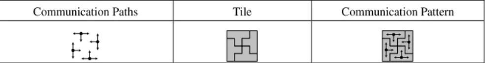
Each primitive tile defines the structure among the nodes but initially does not de-scribe the dynamic behavior among these nodes. Hence, after defining the primitive tiles, we need to define the dynamic behavior among the nodes. This is defined using communication patterns for each tile configuration. A communication pattern in-cludes communication paths that consist of a source node, a target node and a route between the source and target nodes. An example communication pattern is shown in Fig. 7.
Communication Paths Tile Communication Pattern
Fig. 7. Communication patterns constructed with tile and matching communication paths
3.4 Define Operations
To define the mapping of an algorithm to a computing platform we consider an algo-rithm as consisting of a number of sections that include either parallel or serial code. As shown in the metamodel in Fig. 5 each section is mapped to a primitive operation that represents a reusable abstraction of recurring instructions in parallel algorithms. We can identify for example the following primitive operations: Scatter that distrib-utes a set of data to nodes; Gather that collects data from nodes; Reduce that confines a mapped data. To realize an operation a corresponding communication pattern will be needed in the logical configuration. In general, one operation could be realized using different communication patterns. Fig. 8 shows, for example, some of the pos-sible communication patterns for the scatter primitive operation.
Operation 2x2 3x3 4×4
Scatter
Fig. 8. Example communication patterns on different tiles for selected primitive operations
Each operation will in the end run on the tiles of the logical configuration. To compose the logical configuration using the primitive tiles, the tiles must be scaled to larger dimensions. When the tiles are scaled to a larger size, the operations, in other words the communication patterns assigned to operations, must also be scaled to larg-er logical configuration. Hlarg-ereby, the scaling strategy of the oplarg-eration affects the ordlarg-er of communication patterns when scaling the operations. Scaling strategy is the order of communication pattern generation for operation as bottom up or top down.
3.5 Analyze Algorithm
In the previous steps we composed our reusable library with the primitive tiles, commu-nication patterns and operation. Hereby, to support the mapping of the algorithm to paral-lel computing platform, first we need to analyze the paralparal-lel algorithm. In this paper, the complete-exchange algorithm is selected for demonstrating the approach. Since the in-herent complexity of the algorithm is relatively high for large input size, providing paral-lel implementations of these algorithms is usually considered to be important.
First of all we identify the separate sections of the algorithm. This is typically de-fined by considering separate code blocks which form a coherent set of steps to per-form a computation. For example in Fig. 9 we have identified three separate sections for the complete exchange algorithm. The first section defines the transfer process of the data from the dominated nodes to the dominating nodes. The second section de-fines the exchange of the selected messages between the dominating nodes. Finally the third section defines the distribution of the data from dominating nodes to the dominated nodes. Note that the second and third sections belong to the same for loop, but they have been distinguished as separate sections since they form two separate coherent set of steps.
NO PAR/SER Algorithm Section
1 PAR Procedure Complete-Exchange:
For i=1 to n-1
Collect data to the dominating nodes from the domi-nated nodes
Endfor
2 PAR For i=n-1 downto 1
Exchange the selected data between dominating nodes
3 PAR Distribute data from dominating nodes to the dominat-ed nodes
Endfor
Fig. 9. Sections of Complete Exchange Algorithm
The second step of the analysis includes the characterization of the serial (SER) and parallel sections (PAR) of the algorithm. A serial section is a part of the algorithm that will run on a single node, for instance an arithmetic operation. Typically a serial section is identified with a serial code block. A parallel section is the part of the algorithm to coordinate data with communications to be processed on different nodes. The decision of the section types of an algorithm is carried out manually by the parallel programming engineer. This is because the automatic analysis of the parallel algorithms is not trivial and no tool support has been provided for this yet. Moreover, the manual approach ena-bles the parallel programming engineer to support different selection decisions, if this is possible with respect to the properties of the analyzed algorithm.
3.6 Select Logical Configuration Size
The selected algorithm will run on a number of processors that together form the logi-cal configuration. The logilogi-cal configuration size states the number of processors and determines which primitive tiles and communication patterns will be selected from the reusable library to construct the logical configuration. The primitive tiles and
communication patterns are selected based on the scale factors that are calculated using the logical configuration size. The scale factor is the ratio of a logical tion size to another logical configuration size. For example a 6x6 logical configura-tion has a scale factor of 3 to a 2x2 logical configuraconfigura-tion. Hereby, we can construct a 6x6 logical configuration using a 3x3 logical configuration each node consisting of 2x2 logical configuration.
To calculate all the scale factors of a logical configuration we adopt prime factori-zation [18]. Prime factorifactori-zation is the decomposition of a composite number into smaller primitive numbers. The primitive tiles with the primitive size numbers can be scaled to larger logical configuration by using prime factors as scale factors. For ex-ample if we have a 12x12 torus topology, the prime factors of 12 are 2, 2 and 3. As such, we can use a 3x3, and two 2x2 primitive tiles to construct the entire logical topology.
3.7 Generate Alternative Models
After finding the scale factors of logical configuration and decomposing the algorithm to parallel and serial sections, we can now generate the alternative mapping models. Since we labeled each algorithm section as PAR or SER, we need to select communi-cation patterns assigned to operations from parallel domain library.
For complete-exchange example, gather, scatter and exchange operations are de-fined for various primitive tiles. Fig. 10 shows the example 2x2 (named as A2) and 3x3 (named as A3) size primitive tiles and patterns.
Fig. 10. Complete Exchange Operations
To generate the Parallel Algorithm Mapping Model (PAMMO), the patterns that are assigned to operations are scaled according to scale factors that are found by prime factorization. For example for 12x12 topology, the scale factors are found as 3, 2 and 2. A3S, A2S and A2S patterns are selected from the library to generate scatter operation. After selection of patterns, a sequence of patterns for each scale factor is generated. Fig. 11 shows this generated sequence of scatter operation patterns for 12x12 logical configuration.
Tile Scatter Gather Exchange
A2 A2S A2G A2E
The model generation algorithm is given in Fig. 12. Hereby, if the section is serial, than the serial code part is directly gathered to the mapping model. If the section is parallel, the pattern for the operation is generated whether the scaling strategy is UP or DOWN.
Fig. 11. Scatter operation patterns for a 12x12 topology
Procedure GenerateModel (section, size)
if typeof(section) = SER then Add section with code endif
if typeof(section) = PAR then
Get the operation pattern from PAML
if scaling = UP then create pattern bottom up endif
if scaling = DOWN then create pattern top down endif ScalePattern(pattern, size)
endif
for each subsection in section GenerateModel(subsection) endfor
end
Fig. 12. Pseudo code for generating models
The algorithm just generates the one possible mapping for the algorithm. To gener-ate all alternative mapping models, all variants of scale factors are found by using permutation. For example for 12x12 topology, scale factors [3,2,2] will have three permutations of [3,2,2], [2,3,2] and [2,2,3].
3.8 Select Feasible Model
After generating the possible mapping alternatives a feasible alternative needs to be selected by the parallel computing engineer. As stated before in section 2, alternatives will be selected based on the performance metric values for the number of cores used, port count used, and communication length. The calculation of the number of cores used is defined by summing all the cores that appear in the communications for exe-cuting the algorithm. The calculation of the number of ports is defined by summing the ports of the source and target nodes in the communications. Finally, the communi-cation length is calculated by summing up the paths that occur within the communica-tions for executing the algorithm.
3.9 Model Transformations
The previous steps have focused on analyzing the parallel algorithm and selecting a feasible mapping alternative. Subsequently, the algorithm needs to be implemented on
the computing platform that is represented by the logical configuration. In practice there are several computing platforms to implement the mapping such as, MPI, OpenMP, MPL, and CILK [15]. For different purposes different platforms might need to be selected. For example, if the parallel computing platform is built using distribut-ed memory architecture then the MPI implementation platform nedistribut-eds to be chosen. In case shared memory architecture is used then OpenMP will be typically preferred. Other considerations for choosing the implementation platform can be driven by per-formance of these platforms.
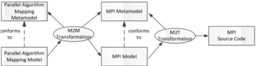
Fig. 13. Example model transformation chain of selected parallel algorithm mapping model in which a MPI implementation platform is chosen
To support the required platform independence requirement we apply the concepts of Model-Driven Architecture [19] in which a distinction is made between platform independent models (PIM), platform specific models (PSM) and code. In our case the PIM is represented by the logical configuration on which the parallel algorithm is mapped. We term this as Parallel Algorithm Mapping Model (PAM). The PSMs can be defined based on the existing parallel computing platforms. In Fig. 13 we show an example transformation chain for mapping the PAM to the MPI Model [20]. The mapping is defined by the M2M Transformation. MPI [20] is a popular and widely used parallel programming framework that adopts language-independent specifica-tions to program parallel computers.
Fig. 14. MPI metamodel
Fig. 14 shows the metamodel for the MPI platform, which is used in the model transformation chain in Fig. 13. A typical MPI model defines the abstract processes and the communications that will run on the nodes, which together realize the parallel algorithm. An MPI model consists of a number of MPIGroup objects that define the selection and configuration of physical nodes. MPIGroup includes MPISections, which are composed of Processes. Process has Communication structures for mes-sage passing between the nodes.
From the final MPI model eventually the required code will be generated using M2T transformation techniques [21]. The details about the transformation will be explained in the next section in which we describe the tool that implements the ap-proach.
4
Tool
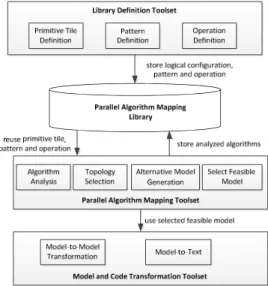
For supporting the process as defined in the previous sections we have developed the tool ParMapper1. This tool is a Java based application that can run on any Java Virtual Machine. The conceptual architecture of ParMapper is shown in Fig. 15. ParMapper includes two different types of tools including (1) tools for defining and preparing the configurations and likewise the development of the library, and (2) tools for defining the mapping of an algorithm to a given parallel computing platform using the library. The Library Definition Toolset supports the steps for defining primitive tiles (section 3.2), defining patterns (section 3.3), and defining the corresponding operations (sec-tion 3.4). The remaining steps of the process are supported by the Parallel Algorithm Mapping Toolset for analyzing algorithm (section 3.5), selecting topology size (sec-tion 3.6), generating alternative models (sec(sec-tion 3.7), and selecting the feasible model (section 3.8). The last step of the process, model transformations, (section 3.9) is sup-ported by third party transformation tools like ATL [22] and XPand [23].
Fig. 15. Conceptual Architecture of the ParMapper Tool
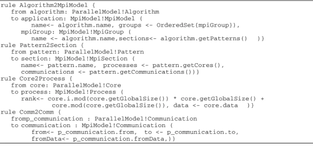
The Model and Code Transformation Toolset are implemented in the Eclipse De-velopment environment. For M2M and M2T transformations we used ATL and XPand, respectively. Fig. 16 shows part of the transformation rules from PAMM to
1
The tool can be downloaded from
MPI metamodel. The transformation rules define the mapping of the communication patterns to MPI sections, cores to processes and communications to MPI communica-tions. Fig. 17 shows part of the XPand code templates that we implemented to trans-form a MPI model to C code. In the first part of the template the MPI initializations and type definitions are provided (not shown). Subsequently, for each section the data initialization and the communication between the processes are defined. Each section is finalized with a barrier command that triggers the next step in the control flow of the parallel algorithm.
rule Algorithm2MpiModel {
from algorithm: ParallelModel!Algorithm to application: MpiModel!MpiModel (
name<- algorithm.name, groups <- OrderedSet{mpiGroup}), mpiGroup: MpiModel!MpiGroup (
name <- algorithm.name,sections<- algorithm.getPatterns() )} rule Pattern2Section {
from pattern: ParallelModel!Pattern to section: MpiModel!MpiSection (
name<- pattern.name, processes <- pattern.getCores(), communications <- pattern.getCommunications())} rule Core2Process {
from core: ParallelModel!Core to process: MpiModel!Process (
rank<- core.i.mod(core.getGlobalSize()) * core.getGlobalSize() + core.mod(core.getGlobalSize()), data <- core.data )} rule Comm2Comm {
fromp_communication : ParallelModel!Communication to communication : MpiModel!Communication (
from<- p_communication.from, to <- p_communication.to, fromData<- p_communication.fromData,)}
Fig. 16. Transformation rules from PAMM to MPI metamodel
«IMPORT mpi»
… // MPI initializations and type definitions «FOREACH groups AS group»
«FOREACH group.sections AS section» «FOREACH section.processes AS process» «FOREACH process.data AS data» «data.type»* «data.name»;
if(rank == «process.rank») «data.name» = («data.type»*) malloc(«data.size»*sizeof(«data.type»)); «ENDFOREACH»
«ENDFOREACH»
«FOREACH section.communications AS comm» if(rank == «comm.from.rank») {
MPI_Isend(«comm.fromData.name», «comm.fromData.size», MPI_«comm.fromData.type», «comm.to.rank», «comm.from.rank», MPI_COMM_WORLD, &request); }
if(rank == «comm.to.rank») {
MPI_Irecv(«comm.toData.name»+«(comm.toData.size/4) * 0», «comm.fromData.size», MPI_«comm.toData.type», «comm.from.rank», MPI_ANY_TAG, MPI_COMM_WORLD, &request); } «ENDFOREACH» MPI_Barrier(MPI_COMM_WORLD); «ENDFOREACH» «ENDFOREACH» … // Final code
Fig. 17. Transformation template from MPI metamodel to MPI source code
5
Evaluation
In the previous sections we have provided a model-driven development approach for generating the mapping alternatives. Obviously, for large scale multi core platform
the question is whether the alternatives are generated in feasible time. We have evalu-ated the generation process by considering various logical configuration sizes for the mapping alternatives of the complete exchange algorithm that is defined in the prob-lem statement section. The mapping alternatives have been generated on a multicore PC with 12 core Intel Xeon 2.67Ghz processor and 40 GB of RAM.
Table 1 shows the result of the evaluation. The left column of the table shows the adopted logical configuration size which range from 36x36 to 1296x1296. The latter configuration size is typical for exascale computing. The middle column shows the number of generated mapping alternatives. The right column shows the time-to-generate the total number of alternatives. For the largest logical configuration size (1296x1296) the overall time to generate the alternatives took around 3 hours, which we consider to be feasible for that scale. We could reduce the time further by running the program on an even more powerful machine.
Table 1. Mapping model generation times
Logical Configuration Size # Mapping Alternatives Time To Generate
1296 (36x36) 6 00:00:02 5184 (72x72) 10 00:00:05 46656 (216x216) 20 00:00:55 419904 (648x648) 35 00:16:44 944784 (972x972) 21 00:22:19 1679616 (1296x1296) 70 02:45:43
Table 2. Metric and time to run values for alternative mappings for complete exchange algorithm
Mapping Calculated Metric Values Measured Values Ports Used Communication Length Core Used Time To Run(ms) Speedup* Efficiency* (for 144 cores) Alternative 1 792 880 516 200.07980 4.9980t 0.0347t Alternative 2 792 952 516 202.37916 4.9412t 0.0343t Alternative 3 792 1024 516 205.23701 4.8724t 0.0338t Alternative 4 792 1024 588 203.90900 4.9041t 0.0340t Alternative 5 792 1024 624 209.87113 4.7648t 0.0330t
*t is the total time for the computation running on single processing unit.
Besides of the evaluation of the generation time that is needed in model-driven transformations we have also looked at the speedup and efficiency measures for the generated alternatives. Since we used a PC with 12 cores we run the generated five alternatives from a 12x12 logical configuration size. Table 2 shows the measurement results of the parallel application that uses the complete exchange algorithm (5 map-ping alternatives) for exchanging data while executing the parallel computations. The columns Port Number, Communication Length and Core Used are computed by ParMapper tool. The column Time To Run is measured, based on which the Speedup and Efficiency values are calculated (See equations (1) and (2) in section 2). To achieve reliable results we have in fact run the program 1000 times for each alterna-tive and took the mean value of these 1000 runs.
From Table 2, we can derive that calculated metric values of ParMapper seem to directly correlate with the measured values. For example, in the table it appears that
Alternative 1 has the minimal time to run value and as such will perform the most optimal with respect to the speedup and efficiency metrics. If we look at the calculat-ed metric values on the left of the table then we can see that these are also minimal values with respect to the other alternatives.
6
Related Work
Optimizing the mapping of parallel algorithms to parallel computing platforms has been addressed before and several tools have been introduced. These tools very often support the optimization of the mapping process by tracing or profiling the applica-tions during run-time. Examples of these tools are TAU [24], HPC Toolkit [25], Open|Speedshop[26], and Scalasca[27]. Since the optimization is done at run-time these tools usually require that the implementation of the algorithm is completed be-fore the analysis. However, for large scale parallel computing platforms the effort for the implementation is usually substantially high and as such an early analysis ap-proach as defined in ParMapper is needed. Integration of ParMapper with existing profiling tools can be helpful to achieve an optimization after running the feasible alternative. Tools such as CUDA-CHiLL[28] and hiCUDA [29], support code genera-tion and also include mechanism to auto tune the code. But the analysis is again done after the implementation. Moreover, the space of different implementation alterna-tives and the reasoning with respect to metrics of speedup and efficiency is not direct-ly supported.
ParMapper supports a model-driven approach to support different platform specific parallel programming frameworks and code generation. Similarly Gamatié et al. [30] present the so-called GASPARD design framework for massively parallel embedded systems. In GASPARD, high-level specifications of an embedded system are defined with the MARTE standard profile [31]. The resulting models are then automatically refined into low-level implementations. Different from ParMapper the approach as used in Gaspard does neither provide early analysis nor the design space generation and exploration of feasible mappings. Sussman [32] explains a model-driven mapping approach for distributed memory parallel computers. But this approach provides a running framework and does not support code transformation.
7
Conclusion
In this paper we have provided a systematic approach and the corresponding tool support for mapping parallel algorithms to parallel computing platforms. We have illustrated the approach for the complete exchange algorithm. With the tool we could generate the logical configurations for even large scale multi core applications such as in exascale computing. We have evaluated the approach by considering the required time for generating the models, as well as the reliability of the generated alternatives with respect to the actually measured values. Our study shows that ParMapper is reli-able and can be used by parallel computing engineers to generate alternative map-pings, provide an early analysis of these with respect to speedup and efficiency, and generate the platform specific model and the source code.
The tool is publicly made available to share our results and get feedback from the parallel computing community. Although we have applied the approach for one parallel computing algorithm, we believe that the approach is general and can be ap-plied to other algorithms as well. In our approach we have assumed a parallel compu-ting platform based on a distributed memory model. Further we assume a physical configuration that can be organized as mesh or torus that is widely used in parallel computing platforms. In our future work we will also consider the analysis of other parallel algorithms and execute ParMapper program on large scale multi core com-puters. In this context, we will enhance the analysis approach by considering various other quality factors such as power consumption and memory consumption and we will consider possible extensions to metamodels and approach.
References
1. Moore, G.E.: Cramming More Components Onto Integrated Circuits. Proceedings of the IEEE 86(1), 82–85 (1998)
2. Aizcorbe, A.M., Kortum, S.S.: Moore’s Law and the Semiconductor Industry: A Vintage Model. Scandinavian Journal of Economics 107(4), 603–630 (2005)
3. Frank, M.P.: The physical limits of computing. Computing in Science & Engineering 4(3), 16–26 (2002)
4. Amdahl, G.M.: Validity of the Single Processor Approach to Achieving Large Scale Com-puting Capabilities. Reprinted from the AFIPS Conference Proceedings, Atlantic City, N.J., April 18-20, vol. 30, pp. 483–485. AFIPS Press, Reston (1967); when Dr. Amdahl was at International Business Machines Corporation, Sunnyvale, California. IEEE Solid-State Circuits Newsletter 12(3), 19–20 (Summer 2007)
5. Gustafson, J.L.: Reevaluating Amdahl’s law. Communications of the ACM 31(5), 532–533 (1988)
6. Hill, M.D., Marty, M.R.: Amdahl’s Law in the Multicore Era. Computer 41(7), 33–38 (2008)
7. Karp, A.H., Flatt, H.P.: Measuring parallel processor performance. Commun. ACM 33(5), 539–543 (1990)
8. Kogge, P., Bergman, K., Borkar, S., Campbell, D., Carlson, W., Dally, W., Denneau, M., Franzon, P., Harrod, W., Hiller, J., Karp, S., Keckler, S., Klein, D., Lucas, R., Richards, M., Scarpelli, A., Scott, S., Snavely, A., Sterling, T., Williams, R.S., Yelick, K., Bergman, K., Borkar, S., Campbell, D., Carlson, W., Dally, W., Denneau, M., Franzon, P., Harrod, W., Hiller, J., Keckler, S., Klein, D., Williams, R.S., Yelick, K.: Exascale Computing Study: Technology Challenges in Achieving Exascale Systems. DARPA (2008)
9. İmre, K.M., Baransel, C., Artuner, H.: Efficient and Scalable Routing Algorithms for Col-lective Communication Operations on 2D All–Port Torus Networks. International Journal of Parallel Programming 39(6), 746–782 (2011) ISSN: 0885-7458
10. Kim, S.-G., Maeng, S.-R., Cho, J.-W.: Complete exchange algorithms in wormhole-routed torus networks: a divide-and-conquer strategy. In: Proceedings of the Fourth International Symposium on Parallel Architectures, Algorithms, and Networks (I-SPAN 1999), pp. 296–301 (1999)
11. Suh, Y.-J., Shin, K.G.: All-to-all personalized communication in multidimensional torus and mesh networks. IEEE Transactions on Parallel and Distributed Systems 12(1), 38–59 (2001)
12. Tsai, Y.J., McKinley, P.K.: An extended dominating node approach to collective commu-nication in all-port wormhole-routed 2D meshes. In: Proceedings of the Scalable High-Performance Computing Conference, pp. 199–206 (1994)
13. Chien, A.A., Konstantinidou, M.: Workloads and Performance Metrics for Evaluating Parallel Interconnects, pp. 23–27. Morgan-Kaufmann (Summer-Fall 1994)
14. Zhang, X.D., Yan, Y., He, K.Q.: Latency Metric: An Experimental Method for Measuring and Evaluating Parallel Program and Architecture Scalability. Journal of Parallel and Distributed Computing 22(3), 392–410 (1994) ISSN 0743-7315, 10.1006/jpdc.1994.1100 15. Talia, D.: Models and Trends in Parallel Programming. Parallel Algorithms and
Applica-tions 16(2), 145–180 (2001)
16. Baransel, C., İmre, K.M.: A Parallel Implementation of Strassen’s Matrix Multiplication Algorithm for Wormhole-Routed All-Port 2D Torus Networks. Journal of Supercomputing 62(1), 486–509 (2012)
17. Peters, J.G., Syska, M.: Circuit-Switched Broadcasting in Torus Networks. IEEE Transac-tions on Parallel and Distributed Systems 7(3), 246–255 (1996)
18. Lenstra, H.W., Pomerance, C.: A Rigorous Time Bound for Factoring Integers. Journal of the American Mathematical Society 5(3), 483–516 (1992)
19. Object Management Group (OMG), Model Driven Architecture (MDA), ormsc/2001-07-01 (20ormsc/2001-07-01)
20. MPI: A Message-Passing Interface Standart, version 1.1 (2013),
http://www.mpi-forum.org/docs/mpi-11-html/mpi-report.html 21. Czarnecki, K., Helsen, S.: Feature-based survey of model transformation approaches. IBM
Syst. J. 45(3), 621–645 (2006)
22. ATL: ATL Transformation Language (2013), http://www.eclipse.org/atl/ 23. Xpand, Open Architectureware (2013), http://wiki.eclipse.org/Xpand 24. Shende, S.S., Malony, A.D.: The Tau Parallel Performance System. Int. J. High Perform.
Comput. Appl. 20(2), 287–311 (2006)
25. Adhianto, L., Banerjee, S., Fagan, M., Krentel, M., Marin, G., Mellor-Crummey, J., Tallent, N.R.: HPCToolkit: Tools for performance analysis of optimized parallel programs. Concurrency and Computation: Practice and Experience 22(6), 685–701 (2010)
26. Krell Institute, Open|Speedshop (2013), http://www.openspeedshop.org 27. Geimer, M., Saviankou, P., Strube, A., Szebenyi, Z., Wolf, F., Wylie, B.J.N.: Further
Im-proving the Scalability of the Scalasca Toolset. In: Jónasson, K. (ed.) PARA 2010, Part II. LNCS, vol. 7134, pp. 463–473. Springer, Heidelberg (2012)
28. Rudy, G., Khan, M.M., Hall, M., Chen, C., Chame, J.: A programming language interface to describe transformations and code generation. In: Cooper, K., Mellor-Crummey, J., Sarkar, V. (eds.) LCPC 2010. LNCS, vol. 6548, pp. 136–150. Springer, Heidelberg (2011) 29. Han, T.D., Abdelrahman, T.S.: hiCUDA: High-Level GPGPU Programming. IEEE
Trans-actions on Parallel and Distributed Systems 22(1), 78–90 (2011)
30. Gamatié, A., Le Beux, S., Piel, É., Ben Atitallah, R., Etien, A., Marquet, P., Dekeyser, J.-L.: A Model-Driven Design Framework for Massively Parallel Embedded Systems. ACM Transactions on Embedded Computing Systems 10(4), 1–36 (2011)
31. Object Management Group. A UML profile for MARTE (2009), http://www.omgmarte.org
32. Sussman, A.: Model-driven mapping onto distributed memory parallel computers. In: Proceedings Supercomputing 1992, pp. 818–829 (1992)