for 5G New Radio
Ahmet Yazar1,∗and H¨useyin Arslan1,2
1Istanbul Medipol University, Istanbul, 34810 Turkey 2University of South Florida, Tampa, FL 33620 USA
E-mail: [email protected]; [email protected]
∗Corresponding Author
Received 1 August 2018; Accepted 06 September 2018; Publication 20 September 2018
Abstract
The physical layer of 5G cellular communications systems is designed to achieve better flexibility in an effort to support diverse services and user requirements. Orthogonal frequency division multiplexing (OFDM) wave-form parameters are enriched with flexible multi-numerology structures. This paper gives a short summary for the Third Generation Partnership Project (3GPP) New Radio (NR) standard and then describes the differences of building blocks for Long Term Evolution (LTE) systems and NR from the flexibility perspective. Research opportunities for multi-numerology systems are presented in a structured manner. Finally, inter-numerology interference (INI) and signal-to-interference ratio (SIR) results as a function of multi-numerology parameters, guard allocation and user power levels are obtained through computer simulations.
Keywords: 3GPP, 5G, adaptive scheduling, flexibility, multi-numerology, New Radio, OFDM, waveform.
Journal of Mobile Multimedia, Vol. 14 4, 367–394.
doi: 10.13052/jmm1550-4646.1442 c
1 Introduction
Long Term Evolution (LTE) waveform has a fixed structure that is optimized to serve high data rate applications [1]. There is only limited support for other applications due to the inflexibility of the waveform and LTE cannot support the rich service and user requirements of 5G vision [2]. 5G New Radio (NR) is aimed to provide wide variety of services by rendering waveform parameters flexibly [3]. The new design paradigms make enhanced-mobile broadband (eMBB) experience possible everywhere. The flexibilities introduced to the waveform and frame enable reduced latencies and improved reliability, empowering ultra reliable and low latency communications (uRLLC) in addition to high data rate applications. Moreover, massive machine type communications (mMTC) is enabled for suitable scenarios with NR.
5G flexibility is provided by the coexistence of multiple numerologies, where each numerology consists of a set of parameters defining the frame and lattice structure of the waveform. The same single mother waveform orthogonal frequency division multiplexing (OFDM) is employed for both LTE and NR but in contrast to the single-numerology utilization in LTE, NR allows simultaneous multi-numerology utilization [4].
Different numerologies are multiplexed orthogonally in time domain in [5]. It is one of the first studies that incorporated multi-numerology or mixed-numerology systems and designed a framework that provides numer-ous services simultanenumer-ously in a unified frame. Multiple numerologies are multiplexed in both time and frequency domains with 5G NR [6].
Multi-numerology structures that were included in the Third Generation Partnership Project (3GPP) NR standardization were studied in literature from different aspects. Relationships between multiple numerologies and user/service requirements are provided in [2, 7, 8] from the numerology selection perspective. Non-orthogonality of multi numerologies are inves-tigated in [9–12]. Various inter-numerology interference (INI) estimation and cancellation methods are provided in [6, 9, 13]. Moreover, INI reduction techniques are proposed in [6,9,13–19]. Algorithm examples for the advanced scheduling methods of multiple numerologies explained in [2, 20–23]. A summary for the subjects of these studies are presented in Figure 1 and details for the literature are provided in Section 4.
In this paper, four main contributions have been made as listed below: 1. New concepts introduced in NR are described regarding to 3GPP Release
15 and possible implementation issues are discussed.
2. Building blocks of LTE and NR were compared from the flexibility perspective regarding to 3GPP 38-series standardization documents.
Numerology Selection [2,7,8]
Non-Orthogonality Analysis [9,10,11,12]
INI Estimation and Cancellation [6,9,13]
INI Reduction [6,9,13,14,15,16,17,18,19]
Example Methods for Scheduling [2,20,21,22,23]
• Sidelobe Overlapping with Sufficient Guard Band • Insufficient Guard Band • Overlapped Subcarriers • Individual CP Implementation • Common CP Implementation
• Effects of Guard Bands • Effects of Guard Intervals • Filtering and Windowing
• Optimization on the Number of Active Numerologies • Edge User Scheduling
Figure 1 Various research opportunities for multi-numerology systems.
3. Research opportunities for multi-numerology systems are presented with a structured manner. Non-orthogonality of multiple numerologies is analyzed.
4. Through computer simulations, INI and signal-to-interference ratio (SIR) results as a function of multi-numerology parameters, guard allocation and user power levels are obtained.
The rest of the paper is organized as follows: New concepts introduced in NR are described in Section 2 regarding to 3GPP Release 15. Possible implementation issues are also discussed in this section. Section 3 presents a comparison between LTE and NR building blocks from the flexibility perspective. Research opportunities for potential improvements of multi-numerology systems and non-orthogonality analysis are provided in Section 4. Section 5 shows computer simulation results for multi-numerology structures. Finally, the conclusion is given in Section 6.
2 A Short Summary on 3GPP Release 15
New concepts are introduced and building blocks are defined to provide more flexible radio access technologies (RATs) in 5G NR [24–27]. In this section, concepts that were introduced in NR are defined and possible implementation issues are discussed. Release 15 is taken as the reference.
In 3GPP Release 15, standalone (SA) operation according to [28, 29] and non-SA (NSA) operation coexisting with other technologies according to [30] are defined. NSA operation was finalized in Release 15, but some issues regarding SA operation, along with details necessary to provide mMTC, was left for further study to be finalized in Release 16 that is expected to be completed in in the first quarter of 2020.
Waveform defines how the resources are placed in the time-frequency lattice and the structure (pulse shapes and filters) that maps information symbols to these resources [5]. In the downlink (DL), NR uses (CP)-OFDM with multi numerologies (a mother waveform plus its derivatives). In the uplink (UL), there is an option to use either of CP-OFDM and discrete Fourier transform (DFT)-spread-OFDM (DFT-s-OFDM) with multi numerologies for NR [31].
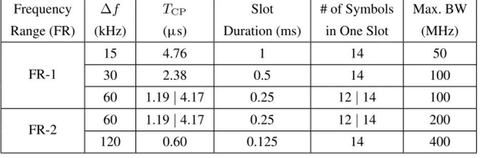
NR defines flexible time-frequency lattice enabling multi-numerology structure. For the case of OFDM, numerology set consists of number of subcarriers, subcarrier spacing (Δf), slot duration and slot duration and CP duration (TCP) [2]. The Δf, TCP, slot duration, and maximum BW allocation options for NR numerologies according to [4] and [32] are presented in Table 1. Individual CP usage for each OFDM symbol is preferred in 3GPP standardization for 5G NR [4]. Different numerologies can be used simultaneously in a cell. However, all of the NR numerologies do not need to be used all the time.
A BW Part (BWP) is a new term that defines a fixed band over which the communication taking place uses the same numerology throughout the existence of the BWP [33]. It is a bridge between the numerology and schedul-ing mechanisms. BWPs are controlled at the base station (BS) based on user equipment (UE) needs and network requirements. BWPs allow UEs to process
Table 1 Numerology Structures and the Corresponding Maximum BW Allocations for Data Channels in 5G
Frequency Δf TCP Slot # of Symbols Max. BW
Range (FR) (kHz) (μs) Duration (ms) in One Slot (MHz)
FR-1 15 4.76 1 14 50 30 2.38 0.5 14 100 60 1.19| 4.17 0.25 12| 14 100 FR-2 60 1.19| 4.17 0.25 12| 14 200 120 0.60 0.125 14 400
only part of the band that contain their symbols, reducing power consumption and enabling longer battery lives. This is very useful for the low-power com-munications systems, particularly mMTC services. NR allows overlapping of BWPs using different numerologies in time-frequency grid [24]. BWPs may overlap to facilitate low latency services while providing data to noncritical services to ensure efficient utilization of resources. BWP is a practical tool for multi-numerology systems as BWP defines a specific numerology. BS can modify UE numerologies by changing it’s BWPs. Parameter configuration process for the BWPs is employed by BW adaptation (BA) tool on BS [34]. There can be up to four defined BWPs for each UE but there is one active BWP for each user in Release 15. However, future NR releases are planned to allow multiple (up to four per UE in Release 16) active BWP configurations. Although not imposed by the standard [4], it is generally preferred that BWPs configured to use the same numerologies consecutively in an effort to reduce guard bands and computational complexity.
BS channel BW is another new term that refers to the contiguous BW currently in use by the next generation node B (gNB) for either transmission or reception [35]. In other words, it refers to the total BW that is processed by the gNB.
NR slots can consist of 14 symbols forΔfs up to 60 kHz [36]. Furthermore, NR Resource Blocks (RBs) are defined only using the same BW definition; their durations are not fixed [4]. NR Transmission Time Interval (TTI) may be a mini-slot in the case of uRLLC or beam-sweeping operation in frequency range-2, a slot for regular operation, or multiple slots in the case of large number of eMBB packets [36]. The number of slots per sub-frame depends on the Δf and is given by the multiplicative inverse of the slot duration seen in Table 1 [4]. Various slot configurations and UE scheduling guidelines reveal that few restrictions exist regarding scheduling users in time domain. This implies that the guard times can also be utilized flexibly, similar to guard bands. Combining time-frequency guard flexibility yields that empty resource elements can virtually be placed anywhere.
In 3GPP standards, it is revealed that there are minimum guard band requirements, a maximum or an optimum value is not enforced, making guard bands choices flexible with high granularity [35]. Additionally, applying proper filtering and windowing methods are left for the implementation in 3GPP standardization. Spectral guards and pulse shapes are critical part of the NR flexibility. These are left for the implementation as long as it is transparent to the counterpart of the communications.
For NR, 3GPP standards give freedom to implement any additional algorithms that BS and UE manufacturers desire as long as it is transparent to the receiver [37]. Various details for possible implementation issues are discussed in Section 4.
3 Flexibility Comparison for Building Blocks of 5G NR and LTE
In this section, the differences of building blocks for LTE and NR are distinguished from the flexibility perspective.
LTE and NR use the same mother waveform but there is only one numerology in LTE. In the UL, the only option in LTE is DFT-s-OFDM with a single numerology. However, there is an option to use either of CP-OFDM and DFT-s-OFDM with multi numerologies for NR.
LTE used a fixed lattice in which the frequency (and corresponding time) spacing between each point was always the same throughout the whole transmission band [3]. LTE is a single-numerology system thus all these parameters are fixed at all times for a BS. On the contrary, NR defines flexible time-frequency lattice enabling multi-numerology structure.
In contrast to LTE, 5G UEs do not need to monitor the whole transmission BW; they only scan the BWPs assigned to themselves.
Unlike LTE slots that consist of 7 OFDM symbols in case of normal CP, NR slots can consist of 14 symbols forΔfs up to 60 kHz [36]. Furthermore, LTE RBs cover 12 consecutive subcarriers over a subframe (i.e., two slots) duration, whereas NR RBs are defined only using the same BW definition; their durations are not fixed [4]. As opposed to the fixed LTE TTI duration of one slot, NR TTI may be a mini-slot. NR re-uses the LTE radio frame definition [38], however, the number of slots per sub-frame depends on the Δf and is given by the multiplicative inverse of the slot duration seen in Table 1 [4].
4 Research Opportunities for Multi-Numerology Systems
As it can be seen from the previous sections, the main flexibility causative for NR is mostly focused on the new frame with multi-numerology. Different UE and service requirements can be met using multiple numerologies. In other words, multiplexing numerologies provides the flexibility needed by NR.
This section presents various research opportunities and exemplary multi-numerology methods that exploit the flexibilities in NR design pointed out in the previous sections. Many new research studies exploit this degree of freedom.
4.1 Numerology Selection Methodologies
Numerologies of UEs cannot be decided arbitrarily. There is a need for a numerology selection mechanism to employ multi-numerology systems with multi UEs. In this subsection, we provide some details on that subject.
Active BWPs and the corresponding numerologies can be selected using different methodologies. Various trade-offs between distinct performance metrics that include spectral efficiency, INI, flexibility, and complexity can be considered while deciding on active BWPs and so numerologies.
For one active BWP at a time case, an example numerology selection methodology is proposed in [2] that uses a heuristic algorithm to configure numerologies suitable for each user. Figure 2 illustrates this resource allocation
Figure 2 Simple representation of numerology selection methodology in a cell serving users with various necessities [2]. User necessities can be gathered by BS at different or same times but numerology decisions are made at the same time.
optimization methodology. The proposed method also provides an active BWP switching mechanism.Δf, TCP, and spectral efficiency requirements of all users in a cell are input to the algorithm.
It is possible to increase the number of numerologies in beyond 5G. Offering more numerologies simultaneously ensures that all user and service requirements are satisfied, but this requires more sophisticated numerology selection mechanisms. To reduce computational costs, BSs may use two-step numerology selection methods in the future. The first step decides on the most suitable numerology set between different sets. Then, the second step determines the best numerologies from the set that is selected in the first step. Additionally, different numerology selection methods may become available for multiple BWPs active at a time case.
In [21], a heuristic solution is proposed while considering the optimization of the data block allocation as a Knapsack problem. In the future, opti-mal numerology assignment methodology can be developed for multiple numerology systems using the Knapsack problem approachment.
4.2 Non-Orthogonality in Multi Numerologies
In this subsection, different implementation structures are presented in the scope of non-orthogonality in multiple numerologies. INI changes tremen-dously regarding the non-orthogonality under different implementations.
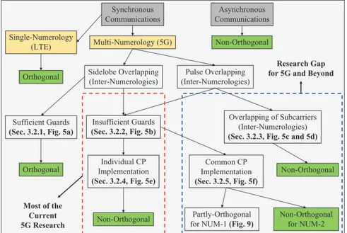
Relationships between different scenarios for inter-numerologies are summarized in Figure 3. Synchronous communications means there is a slot-based synchronicity. In addition, overlapping of multiple numerologies is pulse-based and sidelobe-based. If there is a non-orthogonality for the edge subcarriers, there can be full or partial orthogonality for the inner subcar-riers of multiple numerologies. Here we assume that non-orthogonality of inter-numerologies need to be analyzed for each of the subcarriers separately. Implementation methods are presented in Figure 4. Also, example demonstrations are shown in Figure 5.
4.2.1 Sidelobe overlapping with sufficient guard band
Non-orthogonality can result either from pulse-based or sidelobe-based over-lapping numerologies for the synchronous communications. In the case of sidelobe overlapping subcarriers, the main reason of non-orthogonality is out-of-band (OOB) emission. We can use large guard bands between different numerologies to move away from the spectral leakage and reduce INI.
Synchronous Communications Pulse Overlapping (Inter-Numerologies) Sidelobe Overlapping (Inter-Numerologies) Non-Orthogonal Asynchronous Communications Non-Orthogonal Sufficient Guards (Sec. 3.2.1, Fig. 5a)
Insufficient Guards (Sec. 3.2.2, Fig. 5b) Common CP Implementation (Sec. 3.2.5, Fig. 5f) Individual CP Implementation (Sec. 3.2.4, Fig. 5e) Orthogonal
Non-Orthogonal Partly-Orthogonal
for NUM-1 (Fig. 9)
Non-Orthogonal for NUM-2 Single-Numerology (LTE) Multi-Numerology (5G) Orthogonal Overlapping of Subcarriers (Inter-Numerologies) (Sec. 3.2.3, Fig. 5c and 5d)
Most of the Current 5G Research
Research Gap for 5G and Beyond
Figure 3 Non-orthogonality and partial orthogonality of inter-numerologies for different OFDM-based scenarios. NUM-1 has narrow subcarriers and NUM-2 has wider subcarriers.
Resource elements within the same numerology are orthogonal to each other, but resource elements of any two numerologies with differentΔfs are only orthogonal to each other if sufficient guards exist among them [9, 17].
Effects of guard bands are mentioned in Section 4.4 and the related performance analysis results are given in Section 5.2. Deciding about the required guard bands between multiple numerologies for different scenarios is an important research area. The amount of guard bands affects spectral efficiency inversely proportional.
4.2.2 Insufficient guard band
If the guard amount between multiple numerologies is insufficient or it is a zero-guard case [17], inter-numerology non-orthogonality is inevitable. Most of the studies for the 5G multi-numerology systems can be classified under this scenario.
OOB emission increase INI effects especially for the edge subcarriers of each numerologies. Side lobes decrease from edge to inner subcarriers
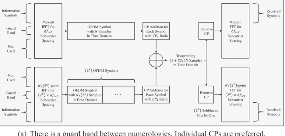
… -point IFFT for ∆ Subcarrier Spacing /(2 )-point IFFT for 2 × ∆ Subcarrier Spacing Not Used Information Symbols OFDM Symbol with Samples in Time Domain OFDM Symbol with / 2 Samples in Time Domain Transmitting (1 + ) Samples in Time Domain -point FFT for ∆ Subcarrier Spacing / 2 -point FFT for 2 × ∆ Subcarrier Spacing 2 Subblocks One by One Received Symbols Received Symbols CP Addition for Each Symbol with Ratio CP Addition for Each Symbol with Ratio Remove CP Remove CP 2 OFDM Symbols Information Symbols Guard Band Not Used Guard Band
(a) There is a guard band between numerologies. Individual CPs are preferred.
… -point IFFT for ∆ Subcarrier Spacing /(2 )-point IFFT for 2 × ∆ Subcarrier Spacing Not Used Not Used Information Symbols OFDM Symbol with Samples in Time Domain OFDM Symbol with / 2 Samples in Time Domain Transmitting (1 + ) Samples in Time Domain -point FFT for ∆ Subcarrier Spacing / 2 -point FFT for 2 × ∆ Subcarrier Spacing 2 Subblocks One by One Received Symbols Received Symbols Common CP Addition Remove Common CP 2 OFDM Symbols Information Symbols Remove Common CP
(b) There is not any guard band between numerologies. Common CP is preferred.
Figure 4 Block diagram for the simple implementation of multi numerologies. The scaling factor ofΔfs is chosen as 2k, wherek is a positive integer.
in all multi-numerology scenarios. Additionally, separation of the composite signal at the receiver unintentionally increase INI during the separation of the composite signal. This situation is discussed more in the next subsections.
Different CP implementation techniques can be employed to decrease INI effects in the scenarios that have insufficient guards. Moreover, alternative INI reduction techniques like filtering and windowing can be preferred as mentioned in Section 4.4. It is also possible to use advanced scheduling techniques like in Section 4.5.
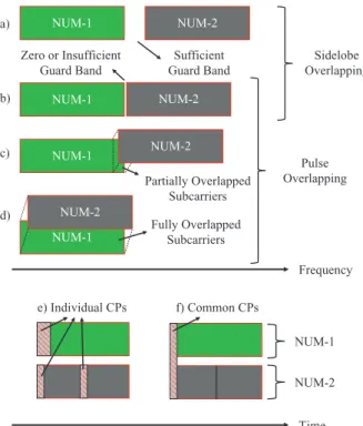
Time e) Individual CPs f) Common CPs NUM-1 NUM-2 Zero or Insufficient Guard Band NUM-1 NUM-2 NUM-1 NUM-2 NUM-1 NUM-2 a) b) c) Frequency Sidelobe Overlapping Pulse Overlapping Sufficient Guard Band Partially Overlapped Subcarriers NUM-1 NUM-2 d) Fully Overlapped Subcarriers
Figure 5 Frequency and time domain demonstrations of the scenarios given in Figure 3. Numerology-1 and Numerology-2 are presented as NUM-1 and NUM-2, respectively. Subcarrier spacing is shown with SCS.
4.2.3 Overlapped subcarriers
Inter-numerology non-orthogonality can be originated from overlapping of subcarriers in a fully or partially manner. In [10], authors proposed a numerology-domain non-orthogonal multiple accessing (NOMA) system with fully-overlapping multi-numerology structures. However, it is also possible to overlap only small amount of subcarriers that belong to multiple numerologies. For the single-numerology systems, partially-overlapping subcarriers scenario is studied in [39]. It is also possible to make a similar system in the multi-numerology domain. Example demonstrations are shown in Figure 5(c) and 5(d).
NR allows overlapping of BWPs using different numerologies in time-frequency grid [24]. Numerology-domain NOMA system designs can be
developed to exploit this gap in 5G. However, receiver complexity increase for the scenarios with the overlapped subcarriers.
Besides these scenarios, subcarriers are non-orthogonal to each other for intra- or inter-numerology domains in asynchronous communications [12]. 4.2.4 Individual CP implementation
CP implementation techniques have effects on non-orthogonality in multi numerologies [9–11]. Individual CP usage for each OFDM symbol is preferred in 3GPP standardization for 5G NR [4]. However, there is an important disadvantage of employing individual CPs.
A composite signal is formed with summing time domain signals of different numerologies at the end of transmitter side as shown in Figure 4(a). There are more than one symbol for the shorter symbol duration numerologies corresponding to one symbol of the other numerology that has a longer symbol duration as shown in Figure 5(e). Therefore, CPs of the shorter symbol duration numerologies corrupt orthogonality of long symbol duration numerology during Fourier transform (FFT) process at the receiver side.
4.2.5 Common CP implementation
For the common CP usage, a composite signal is formed with summing time domain signals of different numerologies before CP addition process as shown in Figures 4(b) and 5(f). One CP is added to the composite signal at the end of transmitter. Hence, the disadvantage of employing individual CPs is prevented because orthogonality is not corrupted during FFT process at the receiver side. There is less INI because of the partial orthogonality for long symbol duration numerology with the common CP implementation. However, there is not any difference between two implementations regarding the short symbol duration numerology.
Common CP also can be useful from the perspectives of spectral efficiency and latency. Advantages of zero-interference subcarriers can be exploited for different purposes like channel estimation. uRLLC users can be scheduled at the short symbol duration numerology side with common CP implementation because there is less INI and this implementation provides more reliable com-munications. Moreover, latency can be reduced by using a shorter common CP in suitable scenarios [40]. Based on all these advantages, it can be said that common CP implementation may be one of the research areas for 5G beyond technologies. Additionally, common CP needs to be arranged according to wireless channel of different UEs and common CP selection of multiple users is also an important research area.
4.3 INI Estimation Models and Cancellation Methods
INI can be simply defined as a leakage between different numerology struc-tures. The amount of INI can vary depending onΔf, BW, guards, CP usage type, filtering/windowing usage, and user power levels. All of these parameters need to be analyzed together to form estimation models for INI. There are some important studies about INI estimation in the literature but they do not include all of the aspects for the INI sources [6, 9]. In these studies, also INI cancellation methods are proposed to remove estimated INI at the receiver.
Authors of [9] shows that no-CP case can be used to estimate structured INI. Common CP implementation can be considered as a similar scenario as stated in Section 4.2. Structured INI can be exploited during the INI cancellation process. The analytical expression of the INI power is estab-lished for windowed OFDM systems in [6]. Another INI estimation method between different transmitter and receiver windowed OFDM numerologies are provided in [13], where the exact calculation of INI using the CIRs and data of all users, as well as estimation techniques for practical cases such as unknown data as well as unknown CIRs are provided.
INI estimation can be used as a feedback to all other adaptive systems that include numerology selection, adaptive guards, filtering/windowing decision, and advanced scheduling methods. Interference models can be very useful for adaptive decision on different algorithms for multi-numerology systems. 4.4 INI Reduction Techniques
Various INI reduction techniques that prevent INI and effects of them are explained in this subsection. Effects of guards analyzed in [14, 17–19]. Different filtering techniques are provided in [9,14–16]. Moreover, windowing methods are discussed in [6, 13, 14].
4.4.1 Effects of guard bands between multi numerologies
This subsection deals with the adjustment of frequency domain guards with respect to estimated INI after numerologies are selected. In 3GPP standards, guard band choices can be flexible [35]. Adaptive guard band concept for different numerologies becomes a crucial research area at this point.
As it is well known, the OFDM signal is well localized in the time domain with a rectangular pulse shape, which corresponds to a sinc pulse in the frequency domain. Sincs cause significant OOB emission and guard bands are needed between two adjacent subbands with different numerologies to handle the interference.
The OOB emission increases as the symbol duration decreases. Therefore, more guard band is required for the numerologies with higherΔf. For the edge subcarriers of two adjacent numerologies, signal to interference plus noise ratio (SINR) decrease is more significant compared to the decrease in remain-ing subcarriers. Most of the interference comes from the edge subcarriers [41]. Grouping services in BWPs reduces the amount of necessary guards and eases scheduling when such fast numerology variations become necessities. Moreover, passing OFDM signal through power amplifiers causes non-linear distortions. The peak-to-average power ratio (PAPR) and OOB emission increase as the number of active subcarriers increases. As a result, more guard band is needed for the transmissions with wider occupied numerology BWs.
In Section 5, the effects of guard bands between multi numerologies with the performance analysis results are shown regarding to the implementation block diagram given in Figure 4(a).
4.4.2 Effects of guard intervals for INI elimination
In addition to guard bands between different numerologies, the guards in time and frequency domains must be jointly optimized to boost the spectral efficiency [19]. The guard times can be utilized flexibly, similar to guard bands. Combining time-frequency guard flexibility yields that empty resource elements can virtually be placed anywhere. Interpreting this at a multi-user level reveals that the UL slot of one UE and the DL slot of another UE can be scheduled to consecutive time or frequency resources with little guard time and band. This poses serious requirements in pulse shaping, making localized pulses and interference rejection techniques critical.
4.4.3 Filtering and windowing in NR
INI cannot be handled only using guards but also with the filtering and win-dowing approaches that require additional guards. Applying proper filtering and windowing methods are left for the implementation of standardization.
Allocating users optimal guards minimizes but not completely eliminates the interference on the received signal in a non-orthogonal system. The receiver may also engage in filtering and windowing to further eliminate the remaining interference, but doing so using conventional methods requires additional guards. The assigned optimum guards may not be sufficient if minimum latencies are required.
The algorithm presented in [13] deals with the minimization of aggregate inter-symbol interference (ISI), inter-carrier interference (ICI) and adjacent channel interference (ACI) by windowing each received subcarrier with the
window function that minimizes the aggregate interference at that subcarrier. The optimal window lengths require perfect knowledge of the interfering users’ data and channels. While this can be known and applied at UL reception at the gNB in a manner similar to successive interference cancellation (SIC) or multi-user (MU) detection, this cannot be done at the UE. Therefore, the algorithm presents methods to estimate optimal subcarrier specific window durations if only the CIRs, power delay profiles (PDPs) or the power offsets of the interferers are known.
4.5 Advanced Scheduling Techniques for Multiple Numerologies
4.5.1 Optimization on the number of active numerologies
Authors of [2] find the efficient number of active numerologies that should be simultaneously employed by users. The algorithm aims to minimize various overheads to provide a practical solution satisfying different service and user requirements using multi-numerology structures. All of the numerologies that are defined in standards do not need to be used all the time.
Basically, the amount of total guard band in the lattice increases with increasing number of numerologies. Hence, there is a trade-off between the spectral efficiency and multi-numerology system flexibility. Although not imposed by the standard [4], they allocate BWPs configured to use the same numerologies consecutively in an effort to reduce guard bands and computational complexity.
4.5.2 Edge user scheduling for multiple numerologies
Edge users of multiple numerologies experience unfairness because most of the INI is concentrated at the edges of numerologies. Intensive INI at the edges causes low reliability for edge UEs. Proper scheduling mechanisms can increase fairness and reliability for these UEs.
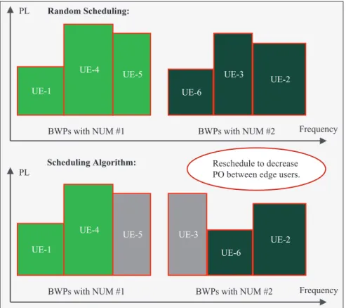
In [20], fairness of UEs at the numerology edges is increased by mini-mizing the INI effects while maintaining spectral efficiency with fixed guard bands. They use three inputs that include service type, power level, and BW of a UE. Their only focus is on edge UEs in the proposed algorithms. The other UEs can be scheduled randomly in frequency domain. Hence, frequency dependent scheduling flexibility does not lose. The main aim is that minimization of the power difference between edge users of multiple numerologies as shown in Figure 6. Performance analysis results for power difference scenarios are provided in Section 5.4.
UE-1 UE-4 UE-5 BWPs with NUM #1 UE-3 UE-2 UE-6 BWPs with NUM #2 UE-1 UE-4 UE-5 BWPs with NUM #1 UE-3 UE-2 UE-6 BWPs with NUM #2 Random Scheduling: Scheduling Algorithm: Frequency PL Frequency PL Reschedule to decrease PO between edge users.
Figure 6 Example demonstration for the edge user scheduling algorithm. Power levels are shown with PL.
Contrary to [20], authors of [19] aim to minimize guard necessities with a fixed SIR and fairness in their scheduling algorithm. In their case, spectral efficiency can be increased due to the fewer guard necessities between different numerologies under desired SIR.
5 Simulation Results for Multi-Numerology Systems
In this section, various INI and SIR results as a function of multi-numerology parameters, guard allocation and user power levels are provided through computer simulations based on the block diagram in Figure 4.
5.1 Assumptions and System Model
It is assumed that UEs are synchronous to each other. We allocate UEs or BWPs with same numerologies contiguously in the frequency domain. It is also assumed that the subcarriers of UEs are sidelobe overlapped to each other and each numerology block that consists of multiple carri-ers is shared by multiple UEs. OFDM is employed and each UEs have different power levels in Section 5.4 and equal power levels in other subsections.
Independent random binary phase shift keying (BPSK) symbols are gener-ated separately for two-numerology structure. For the first numerology, which has Δfref kHz subcarrier spacing, N-point inverse fast Fourier transform (IFFT) is employed. The second numerology has2k× Δfref kHz subcarrier spacing and uses N/(2k)-point IFFT, where 2k is the scaling factor and k is a positive integer. Here, the second half of the IFFT inputs for the first numerology and the first half of the IFFT inputs for the second numerology are zero-padded to separate two numerologies in frequency domain. After each IFFT operation, CP samples are added with a ratio ofCPR to every OFDM symbol. There are2k OFDM symbols with the second numerology corresponding to one OFDM symbol with the first numerology. Thus, the number of samples for each of the numerologies are the same, and they can be added to form a composite signal at the transmitter.
Wireless channel and noise are ignored to just focus on the INI in the simulation results. At the receiver side, CP samples are removed from each OFDM symbol. N-point FFT is used for the first numerology over full composite signal. However, only N/(2k) samples of the com-posite signal to make them input into N/(2k)-point FFT for the second numerology.2k subblocks are constituted by dividing the composite signal into 2k parts and these subblocks are processed one by one. The first half of the FFT output for the first numerology and the second half of the FFT output for the second numerology are taken to obtain received symbols.
Interference estimations for each of the used subcarriers are done sepa-rately. Monte Carlo method is applied and the number of independent tests is 500 with different set of random data in each of these tests. Thereafter, the average interference on the subcarriers are estimated.
5.2 Subcarrier Spacing and Guard Band Effects with Individual CPs
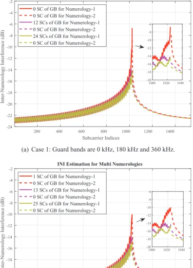
There are four cases in the simulation results presented in Figures 7 and 8. Number of usable subcarriers are half of the IFFT sizes in each case. In Figures 7 and 8, INI results are plotted like that there is not any guard bands between the edge subcarriers of two numerologies when there are actually guard bands. The reason of this representation is to make a comparison with different amount of guard bands easily.
Simulation results show that there is more INI at the edge subcarriers of different numerologies and the effect of guard bands are more prominent for the edge subcarriers. Subblocks of the second numerology are constituted by dividing the composite signal. Hence, the symbols of the first numerology causes an interference on the second numerology at the receiver side. 5.3 Common CP Effects
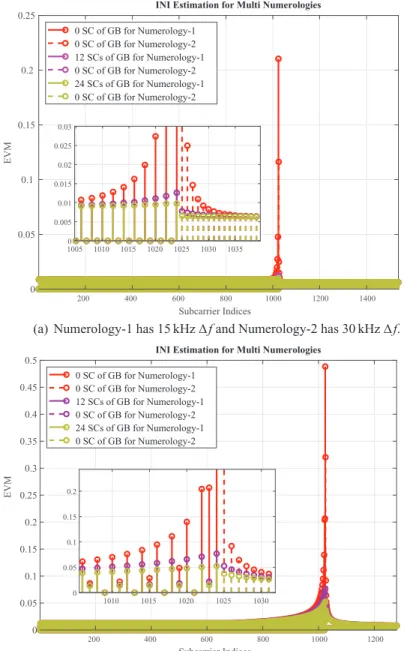
Individual CP addition causes an extra interference for the numerology with smaller Δf as shown in Figures 7 and 8. However, in common CP implementation, INI on every(2k)th subcarrier is zero for the numerology with smallerΔf as it can be seen in Figure 9. It is an important advantage for the short symbol duration numerology. Simulation results support the explanations that are given in Section 4.2.
5.4 Power Difference Effects
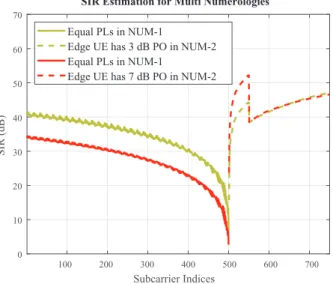
In simulations, power offsets (PO) of the UEs alternate between 0 dB, 3 dB, and 7 dB. For Figure 10(a), increasing the power level of the NUM-2 edge UE 3 dB results with 5.7 dB SIR decrement in the NUM-1 edge UE. PO increment also affects the NUM-1 inner UEs with 4.8 dB. However, there is more than 10 dB SIR difference between the edge UE and inner UE for NUM-1.
For Figure 10(b), increasing the power level of the NUM-1 and NUM-2 UEs symmetrically results with a small SIR increment in the edge UEs of two numerologies. However, inner UEs are affected by the power levels of edge UEs in proportion. These results show that edge user scheduling algorithm presented in Section 4.5 is an effective solution for multi-numerology systems.
200 400 600 800 1000 1200 1400 Subcarrier Indices -24 -22 -20 -18 -16 -14 -12 -10 -8 -6 -4 -2 Inter-Numerology Interference (dB)
INI Estimation for Multi Numerologies 0 SC of GB for Numerology-1 0 SC of GB for Numerology-2 12 SCs of GB for Numerology-1 0 SC of GB for Numerology-2 24 SCs of GB for Numerology-1 0 SC of GB for Numerology-2 1000 1020 1040 -20 -18 -16 -14 -12 -10 -8 -6
(a) Case 1: Guard bands are 0 kHz, 180 kHz and 360 kHz.
200 400 600 800 1000 1200 1400 Subcarrier Indices -24 -22 -20 -18 -16 -14 -12 -10 -8 -6 -4 -2 Inter-Numerology Interference (dB)
INI Estimation for Multi Numerologies 1 SC of GB for Numerology-1 0 SC of GB for Numerology-2 13 SCs of GB for Numerology-1 0 SC of GB for Numerology-2 25 SCs of GB for Numerology-1 0 SC of GB for Numerology-2 1000 1020 1040 -20 -18 -16 -14 -12 -10 -8 -6
(b) Case 2: Guard bands are 15 kHz, 195 kHz and 375 kHz.
Figure 7 Simulation results for two different cases with different guard band amounts between numerologies. Numerology-1 has 15 kHzΔf and Numerology-2 has 30 kHz Δf.
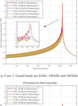
200 400 600 800 1000 1200 Subcarrier Indices -24 -22 -20 -18 -16 -14 -12 -10 -8 -6 -4 -2 Inter-Numerology Interference (dB)
INI Estimation for Multi Numerologies
0 SC of GB for Numerology-1 0 SC of GB for Numerology-2 12 SCs of GB for Numerology-1 0 SC of GB for Numerology-2 24 SCs of GB for Numerology-1 0 SC of GB for Numerology-2 1000 1010 1020 1030 1040 -18 -16 -14 -12 -10 -8 -6 -4 -2
(a) Case 3: Guard bands are 0 kHz, 180 kHz and 360 kHz.
200 400 600 800 1000 1200 Subcarrier Indices -24 -22 -20 -18 -16 -14 -12 -10 -8 -6 -4 -2 Inter-Numerology Interference (dB)
INI Estimation for Multi Numerologies
3 SC of GB for Numerology-1 0 SC of GB for Numerology-2 15 SCs of GB for Numerology-1 0 SC of GB for Numerology-2 27 SCs of GB for Numerology-1 0 SC of GB for Numerology-2 1000 1010 1020 1030 1040 -18 -16 -14 -12 -10 -8 -6 -4 -2
(b) Case 4: Guard bands are 45 kHz, 225 kHz and 405 kHz.
Figure 8 Simulation results for two different cases with different guard band amounts between numerologies. Numerology-1 has 15 kHzΔf and Numerology-2 has 60 kHz Δf.
0 0.05 0.1 0.15 0.2 0.25
INI Estimation for Multi Numerologies
200 400 600 800 1000 1200 1400 Subcarrier Indices 0 SC of GB for Numerology-1 0 SC of GB for Numerology-2 12 SCs of GB for Numerology-1 0 SC of GB for Numerology-2 24 SCs of GB for Numerology-1 0 SC of GB for Numerology-2 0 0.005 0.01 0.015 0.02 0.025 0.03 1005 1010 1015 1020 1025 1030 1035
(a) Numerology-1 has 15 kHzΔ f and Numerology-2 has 30 kHz Δ f.
0 0.05 0.1 0.15 0.2 0.25 0.3 0.35 0.4 0.45 0.5
INI Estimation for Multi Numerologies
200 400 600 800 1000 1200 Subcarrier Indices 0 SC of GB for Numerology-1 0 SC of GB for Numerology-2 12 SCs of GB for Numerology-1 0 SC of GB for Numerology-2 24 SCs of GB for Numerology-1 0 SC of GB for Numerology-2 0 0.05 0.1 0.15 0.2 1010 1015 1020 1025 1030
(b) Numerology-1 has 15 kHzΔ f and Numerology-2 has 60 kHz Δ f.
EVM
EVM
Figure 9 Simulation results for common CP implementation. Guard band amounts between numerologies are 0 kHz, 180 kHz and 360 kHz.
100 200 300 400 500 600 700 Subcarrier Indices 0 10 20 30 40 50 60 70 SIR (dB)
SIR Estimation for Multi Numerologies Equal PLs in NUM-1
Edge UE has 3 dB PO in NUM-2 Equal PLs in NUM-1
Edge UE has 7 dB PO in NUM-2
(a) Edge subcarriers of NUM-2 has higher PLs than the other subcarriers in NUM-1 and NUM-2.
0 10 20 30 40 50 60 70 SIR (dB)
Edge UE has 3 dB PO in NUM-1 Edge UE has 3 dB PO in NUM-2 Edge UE has 7 dB PO in NUM-1 Edge UE has 7 dB PO in NUM-2
(b) Edge subcarriers of NUM-1 and NUM-2 have higher PLs than the inner subcarriers of NUM-1 and NUM-2. There is not any POs between the edge subcarriers.
SIR Estimation for Multi Numerologies
Subcarrier Indices
100 200 300 400 500 600 700
Figure 10 Power difference analysis. NUM-1 has narrow subcarriers with 15 kHz and NUM-2 has wide subcarriers with 30 kHz.
6 Conclusion
Next generation communications systems including NR are evolving towards increased flexibility in different aspects. Enhanced flexibility is the key to address diverse requirements. Some parts of the 5G NR designs are left for the implementation as long as it is transparent to the counterpart of the com-munications. NR flexibility can be exploited by finding optimal and practical solutions for implementation dependent parts of the 5G standardization. The flexibility of NR brings too many open-ended research opportunities compared to the previous cellular communications generations. Most probably, these opportunities will increase with 5G beyond technologies.
Acknowledgement
The authors would like to thank Berker Pek¨oz for his valuable comments and suggestions to improve the quality of the paper.
References
[1] 3rd Generation Partnership Project (3GPP). (2018). Evolved Universal Terrestrial Radio Access (E-UTRA); Physical channels and modulation. Technical Specification 36.211, ver. 15.1.0.
[2] Yazar, A., and Arslan, H. (2018). A flexibility metric and optimization methods for mixed numerologies in 5G and beyond. IEEE Access, 6, 3755–3764.
[3] Ankarali, Z. E., Peköz, B., and Arslan, H. (2017). Flexible Radio Access Beyond 5G: A Future Projection on Waveform, Numerology, and Frame Design Principles. IEEE Access, 5, 18295–18309.
[4] 3rd Generation Partnership Project (3GPP). (2018). NR; Physical channels and modulation. Technical Specification 38.211, ver. 15.2.0. [5] Sahin, A., and Arslan, H. (2012). Multi-user aware frame structure for
OFDMA based system. In Vehicular Technology Conference (VTC Fall), IEEE (pp. 1–5).
[6] Zhang, X., Zhang, L., Xiao, P., Ma, D., Wei, J., and Xin, Y. (2018). Mixed Numerologies Interference Analysis and Inter-Numerology Interference Cancellation for Windowed OFDM Systems. IEEE Transactions on Vehicular Technology.
[7] Ijaz, A., et al. (2016). Enabling massive IoT in 5G and beyond systems: PHY radio frame design considerations. IEEE Access, 4, 3322–3339.
[8] Soni, T., et al. (2018). Adaptive numerology—A solution to address the demanding QoS in 5G-V2X. In Wireless Communications and Networking Conference (WCNC), (pp. 1–6). IEEE.
[9] Zhang, L., et al. (2017). Subband filtered multi-carrier systems for multi-service wireless communications. IEEE Transactions on Wireless Communications, 16(3), 1893–1907.
[10] Abusabah, A. T., and Arslan, H. (2018). NOMA for Multinumerology OFDM Systems. Wireless Communications and Mobile Computing, 2018(1), 1–9.
[11] Nemati, M., and Arslan, H. (2018). Low ICI symbol boundary alignment for 5G numerology design. IEEE Access, 6, 2356–2366.
[12] Do˘gan, S., Tusha, A., and Arslan, H. (2018). OFDM with Index Modulation for Asynchronous mMTC Networks. Sensors, 18(4), 1280. [13] Peköz, B., Köse, S., and Arslan, H. (2017). Adaptive windowing of insufficient CP for joint minimization of ISI and ACI beyond 5G. In IEEE 28th Annual International Symposium on Personal, Indoor, and Mobile Radio Communications (PIMRC), (pp. 1–5). IEEE.
[14] Guan, P., et al. (2017). 5G field trials: OFDM-based waveforms and mixed numerologies. IEEE Journal on Selected Areas in Communica-tions, 35(6), 1234–1243.
[15] Iwabuchi, M., et al. (2017). 5G field experimental trial on frequency domain multiplexing of mixed numerology. In IEEE 85th Vehicular Technology Conference (VTC Spring), 2017 (pp. 1–5). IEEE.
[16] Weitkemper, P., et al. (2016). On regular resource grid for filtered OFDM. IEEE Communications Letters, 20(12), 2486–2489.
[17] Zaidi, A. A., et al. (2016). Waveform and numerology to support 5G services and requirements. IEEE Communications Magazine, 54(11), 90–98.
[18] Demmer, D., et al. (2018). Analytical study of 5G NR eMBB co-existence. arXiv preprint. Available online at: arXiv:1805.05591. [19] Demir, A. F., and Arslan, H. (2017). The impact of adaptive guards for 5G
and beyond. In IEEE 28th Annual International Symposium on Personal, Indoor, and Mobile Radio Communications (PIMRC), (pp. 1–5). IEEE. [20] Yazar, A., and Arslan, H. (2018). Fairness-Aware Scheduling in Multi-Numerology Based 5G New Radio. Available online at: arXiv:1806.04072.
[21] A. Gonzalez et al. (2017). Resource Allocation for Block-Based Multi-Carrier Systems Considering QoS Requirements.In IEEE Conference on Global Communications (GLOBECOM), Singapore.
[22] Akhtar, A., and Arslan, H. (2018). Downlink resource allocation and packet scheduling in multi-numerology wireless systems. In Wireless Communications and Networking Conference Workshops (WCNCW), (pp. 362–367). IEEE.
[23] You, L., et al. (2018). Resource Optimization with Flexible Numerology and Frame Structure for Heterogeneous Services. Available online at: arXiv:1801.02066.
[24] Jeon, J. (2018). NR wide bandwidth operations. IEEE Communications Magazine, 56(3):42–46.
[25] Parkvall, S., et al. (2017). NR: the new 5G radio access technology. IEEE Communications Standards Magazine, 1(4), 24–30.
[26] Lin, X. et al. (2018). 5G New Radio: Unveiling the Essentials of the Next Generation Wireless Access Technology. Available online at: arXiv:1806.06898.
[27] Zaidi, A. A., et al. (2018). OFDM Numerology Design for 5G New Radio to Support IoT, eMBB, and MBSFN. IEEE Communications Standards Magazine, 2(2), 78–83.
[28] 3rd Generation Partnership Project (3GPP). (2018). NR; User Equipment (UE) radio transmission and reception; Part 1: Range 1 Standalone. Technical Specification 38.101-1, ver. 15.1.0.
[29] 3rd Generation Partnership Project (3GPP). (2018). NR; User Equipment (UE) radio transmission and reception; Part 2: Range 2 Standalone. Technical Specification 38.101-2, ver. 15.1.0.
[30] 3rd Generation Partnership Project (3GPP). (2018). NR; User Equipment (UE) radio transmission and reception; Part 3: Range 1 and Range 2 Interworking operation with other radios. Technical Specification 38.101-3, ver. 15.1.0.
[31] 3rd Generation Partnership Project (3GPP). (2017). Study on new radio access technology Radio interface protocol aspects. Technical Report 38.804, ver. 14.0.0.
[32] 3rd Generation Partnership Project (3GPP). (2018). NR; Base Station (BS) radio transmission and reception. Technical Specification 38.104, ver. 15.1.0.
[33] 3rd Generation Partnership Project (3GPP). (2018). NR; Physical layer procedures for control. Technical Specification 38.213, ver. 15.2.0. [34] 3rd Generation Partnership Project (3GPP). (2018). NR; Overall
descrip-tion; Stage-2. Technical Report 38.300, ver. 15.2.0.
[35] 3rd Generation Partnership Project (3GPP). (2018). General aspects for UE RF for NR. Technical Report 38.817-01, ver. 2.0.0.
[36] 3rd Generation Partnership Project (3GPP). (2017). Study on new radio access technology Physical layer aspects. Technical Report 38.802, ver. 14.2.0.
[37] 3rd Generation Partnership Project (3GPP). (2017). Study on new radio access technology. Technical Report 38.912, ver. 14.1.0.
[38] 3rd Generation Partnership Project (3GPP). (2018). NR; Physical layer; General description. Technical Specification 38.201, ver. 15.0.0. [39] Celebi, M. B., and Arslan, H. (2015). Theoretical analysis of the
co-existence of LTE-a signals and design of an ML-SIC receiver. IEEE Transactions on Wireless Communications, 14(8), 4626–4639.
[40] Lorca, J. (2015). Cyclic prefix overhead reduction for low-latency wireless communications in OFDM. In IEEE 81st Vehicular Technology Conference (VTC Spring), (pp. 1–5). IEEE.
[41] Sahin, A., and Arslan, H. (2011). Edge windowing for OFDM based systems. IEEE Communications Letters, 15(11), 1208–1211.
Biographies
Ahmet Yazar received his B.Sc. degree in electrical engineering from Eskise-hir Osmangazi University, EskiseEskise-hir, Turkey in 2011 and M.Sc. degree in electrical engineering from Bilkent University, Ankara, Turkey in 2013. From 2011 to 2013, he was a member of the Bilkent Signal Processing Group where he studied Wavelet Theory and some other signal processing methods in various pattern recognition projects. In 2013, he joined the Information and Communication Technologies Authority and he worked in Spectrum Management Department. At the beginning of 2014, he was appointed under the Presidency of Telecommunication and Communication for one year. He is currently pursuing the Ph.D. degree as a member of the Communications,
Signal Processing, and Networking Center (CoSiNC) at Istanbul Medipol University. His current research interests are flexible waveform systems and multi-numerology structures.
H ¨useyin Arslan received the B.S. degree from Middle East Technical Univer-sity, Ankara, Turkey, in 1992, and the M.S. and Ph.D. degrees from Southern Methodist University, Dallas, TX, USA, in 1994 and 1998, respectively. From 1998 to 2002, he was with the Research Group, Ericsson Inc., NC, USA, where he was involved with several projects related to 2G and 3G wireless communication systems. Since 2002, he has been with the Electrical Engineering Department, University of South Florida, Tampa, FL, USA. He has also been the Dean of the College of Engineering and Natural Sciences, Istanbul Medipol University, since 2014. He was a part-time Consultant for various companies and institutions, including Anritsu Company, Morgan Hill, CA, USA, and The Scientific and Technological Research Council of Turkey (T ¨UB˙ITAK). His research interests are in physical layer security, mmWave communications, small cells, multicarrier wireless technologies, co-existence issues on heterogeneous networks, aeronautical (high-altitude platform) communications, in vivo channel modeling, and system design.
![Figure 2 Simple representation of numerology selection methodology in a cell serving users with various necessities [2]](https://thumb-eu.123doks.com/thumbv2/9libnet/5439385.104264/7.918.204.691.569.867/figure-simple-representation-numerology-selection-methodology-serving-necessities.webp)