Reconfigurable MRI coil technology can
substantially reduce RF heating of deep
brain stimulation implants: First in-vitro study
of RF heating reduction in bilateral DBS leads
at 1.5 T
Laleh GolestaniradID1,2*, Ehsan Kazemivalipour3, Boris Keil4, Sean Downs5, John Kirsch5, Behzad Elahi6, Julie Pilitsis7, Lawrence L. Wald5
1 Department of Biomedical Engineering, McCormick School of Engineering, Northwestern University, Evanston, IL, United States of America, 2 Department of Radiology, Feinberg School of Medicine, Northwestern University, Chicago, IL, United States of America, 3 Department of Electrical and Electronics Engineering, Bilkent University, Ankara, Turkey, 4 Department of Life Science Engineering, Institute of Medical Physics and Radiation Protection, Giessen, Germany, 5 A. A. Martinos Center for Biomedical Imaging, Massachusetts General Hospital, Boston, MA, United States of America, 6 Department of Neurology, Bryan Health, Lincoln, NE, United States of America, 7 Department of Neurosurgery, Albany Medical Center, Albany, NY, United States of America
Abstract
Patients with deep brain stimulation (DBS) implants can significantly benefit from magnetic resonance imaging (MRI), however access to MRI is restricted in these patients because of safety concerns due to RF heating of the leads. Recently we introduced a patient-adjustable reconfigurable transmit coil for low-SAR imaging of DBS at 1.5T. A previous simulation study demonstrated a substantial reduction in the local SAR around single DBS leads in 9 unilateral lead models. This work reports the first experimental results of temperature mea-surement at the tips of bilateral DBS leads with realistic trajectories extracted from postoper-ative CT images of 10 patients (20 leads in total). A total of 200 measurements were
performed to record temperature rise at the tips of the leads during 2 minutes of scanning with the coil rotated to cover all accessible rotation angles. In all patients, we were able to find an optimum coil rotation angle and reduced the heating of both left and right leads to a level below the heating produced by the body coil. An average heat reduction of 65% was achieved for bilateral leads. When considering each lead alone, an average heat reduction of 80% was achieved. Our results suggest that reconfigurable coil technology introduces a promising approach for imaging of patients with DBS implants.
Introduction
Deep brain stimulation (DBS) is a reversible and adjustable neurostimulation technique in which specific brain structures and circuits are electrically stimulated by means of metallic
a1111111111 a1111111111 a1111111111 a1111111111 a1111111111 OPEN ACCESS
Citation: Golestanirad L, Kazemivalipour E, Keil B,
Downs S, Kirsch J, Elahi B, et al. (2019) Reconfigurable MRI coil technology can substantially reduce RF heating of deep
brain stimulation implants: First in-vitro study of RF heating reduction in bilateral DBS leads at 1.5 T. PLoS ONE 14(8): e0220043.https://doi.org/ 10.1371/journal.pone.0220043
Editor: Xi Chen, McLean Hospital, UNITED STATES Received: November 24, 2018
Accepted: July 8, 2019 Published: August 7, 2019
Copyright:© 2019 Golestanirad et al. This is an open access article distributed under the terms of theCreative Commons Attribution License, which permits unrestricted use, distribution, and reproduction in any medium, provided the original author and source are credited.
Data Availability Statement: Because of
restrictions due to patient privacy, we are unable to share de-identified CT images of patients. Although the de-identification process will eliminate HIPPA information from imaging datasets, such 3D volumetric images can be easily used, by use of any opensource image segmentation software, to reconstruct 3D surfaces of patients head and face. Such reconstructions will reveal enough details of the face that allows patients to be identified. Any request on data accessibility should refer to
electrodes connected to an implantable pulse generator (IPG) via subcutaneous insulated wires. The US Food and Drug Administration (FDA) approved DBS as a treatment of essential tremor and Parkinson’s disease (PD) in 1997, dystonia in 2003 [1], obsessive-compulsive disorder (OCD) in 2009 [2], and recently epilepsy in 2018 [3]. Beside this, in recent years DBS has been extensively used in open-label studies to treat Tourette’s Syndrome [4,5], bipolar disorder [6], Schizophrenia [7], treatment-resistant depression [8,9], and freezing of gait [10]. The exponen-tial increase in indications of use and application of DBS in neuropsychiatric disorders parallels the large availability and need for MRI. Particularly, MRI has been largely leveraged to under-stand the underlying mechanisms of action of neuromodulation systems and more recently to guide therapy. The clinical community however, has been cautious in adopting MRI in DBS patients mostly due to concerns about interaction of MRI fields and the implanted device. This includes for example, distortions that affect image quality (e.g., an in-situ device induces suscep-tibility artifacts), interaction with static magnetic field, loss of device functionality due to inter-ference of gradient fields, but most importantly the potential of thermal injury to patients due to interaction with radiofrequency (RF) fields. Such concerns have led many centers to refrain from performing postoperative MRI on DBS patients mainly to adhere to industry-proposed warnings [11]. In some cases, patients have faced the proposition of explanting their neurosti-mulator to receive a diagnostic MRI [12]. With the advances in neurostimulation technology, some of the above-mentioned concerns have been mitigated: reduction of ferromagnetic mate-rial has reduced the risk of device dislodgment due to static magnetic field [13] and improved device programming has reduced the risk of malfunction due to effect of gradient fields [14]. RF heating however, remains a major issue. The RF safety of MRI in patients with elongated implants has been extensively discussed in the literature [15–23]. Techniques based on parallel transmit pulse tailoring [23–26] and surgical lead management [20,27] have shown promising results in reducing the temperature rise near implanted wires in phantoms during MRI at 1.5T and 3T, but such techniques have not been implemented in clinical settings yet. Recently we introduced a patient-adjustable reconfigurable MRI coil with promising results in reducing SAR amplification near tips of implanted leads [28,29]. The coil system consisted of a polarized rotating birdcage transmitter and a 32-channel close-fit receive array. Such a linearly-polarized transmit coil has a slab-like region of low electric field which can be steered to coin-cide with the implant trajectory by rotating the coil around patient’s head. This will significantly reduce the coupling of electric fields with implanted wires, which in turn reduces the RF induced currents on the leads and the SAR at the tip. In a simulation study with patient-derived realistic models of 9 unilateral DBS leads we demonstrated that a substantial reduction in the local energy deposition can be achieved using this technique [29]. In practice however, most patients with PD or essential tremor receive bilateral implants as it has been shown more effec-tive at controlling appendicular and midline tremor [30]. Additionally, 52% of patients who originally receive unilateral DBS eventually need bilateral stimulation [31]. Considering the fact that the optimal coil rotation angle to minimize the local SAR is dependent on the specific lead trajectory [29], the question arises as whether or not the rotating coil system can ever be used in patients with bilateral DBS implants. In other words, as the maximum SAR-reduction occurs when the lead is fully contained in the low electric field region of the coil, it is crucial to assess if there exists a rotation angle that reduces the heating of both left and right DBS leads to the level below the heating generated by a conventional quadrature coil.
In this work we report, for the first time, measurement results of temperature rise at the tips of bilateral DBS lead implants with realistic trajectories during MRI at 1.5 T using the rotating coil system. Implant trajectories were extracted from CT images of 10 patients with bilateral DBS leads (20 leads in total). Anthropomorphic head phantoms were constructed and implanted with bilateral lead wires and positioned inside the coil system with temperature
Reconfigurable MRI coil technology for DBS imaging
Massachusetts General Hospital Internal Review Boards at: Jesse Ripton, MPH, CIP, Director, IRB Operations, Partners IRB/Human Research Committee (jripton@partners). All other data is already included as tables and graphs in the manuscript.
Funding: LG has received awards R03EB024705
and R00EB021320 from National Institute of Health (NIH).
Competing interests: The authors have declared
probes attached at their tips. For each experiment, the coil was rotated around the head phan-tom covering the full range of accessible angles and the temperature at the tips of implants was recorded at each rotation angle during 2 minutes of continues RF exposure. A total of 200 measurements were performed (10 patients×16–22 measurements per patient). We found that for all realistic bilateral lead trajectories, there existed an optimum coil position that substan-tially reduced the heating of both left and right DBS leads compared to the scanner’s body coil. An average heat reduction of 65% was achieved in the case of bilateral leads. In the case of sin-gle leads, an average heat reduction of 80% was achievable using the rotating coil system.
This work reports the first experimental results of successful application of the reconfigur-able coil technology to reduce heating of bilateral DBS leads.
Methods
The reconfigurable coil system
Details of the theory and construction of the reconfigurable birdcage coil system are given in our previous works [28,29]. In brief, the coil consists of a 16-rung linearly-polarized low-pass birdcage transmitter and a 32-channel close-fit receive arrayFig 1A). Such a linearly-polarized birdcage has a slab-like region of low electric field which can be steered by rotating the coil around patient’s head to coincide with the implant trajectory.Fig 1Bshows the distribution of coil’s electric field on a central axial plane for two different coil rotation angles. The details of coil’s model and finite element simulation setup is given elsewhere [28]. To illustrate the orien-tation of DBS leads with respect to the coil’s electric field, models of bilateral leads were con-structed from CT images of a representative patient (ID10). Image segmentation and 3D model construction are described in our previous work [20]. As it can be observed, by rotating the coil around patient’s head and positioning it at an optimal angle, a substantial portion of the lead trajectory can be contained within the low E field region. This reduces the coupling of the electric fields and conductive wires which in turn reduces the SAR at the implant’s tip. We calculated the maximum of 1g-averaged SAR in two cubic areas of 2cm×2cm×2cm containing all four electrode contacts of each lead.Fig 1Creports the maximum SAR value at two different rotation angles. It is important to note however, that the SAR-reduction performance of the coil and the optimum rotation angle that minimizes the SAR at the tip of each implant is dependent on the lead trajectory [29]. This is in line with previous studies that have empha-sized on the importance of the relationship between implant’s geometry, and the phase and orientation of incident electric field of MRI transmit coils [25,32–37]. For each simulation, the B1+field was calculated as B1+= 0.5(B1x+jB1y) [38] and its value was recorded on an axial
circular plane (diameter = 5cm) passing through the center of the head approximately 1 cm below the tips of electrodes (Fig 1D). The input power of the coil was adjusted at each rotation angle to generated the same spatial mean B1+= 2μT over this central plane.
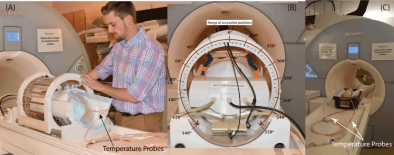
Fig2B and 2Cshows the constructed coil prototype on the patient’s table and the view from back of the coil. The mechanical housing allows the transmitter to rotate smoothly around the receive array and be locked in pre-marked positions which are 5˚ apart. When positioned at the magnet’s iso-center, the coil can be accessed and rotated from the back of the bore, elimi-nating the need to take the patient out for adjustments. Due to mechanical restrictions imposed by positioning of the cables however, the coil cannot rotate in a full circle. The range of accessible angles (0˚-140˚ and 220˚-360˚) are annotated inFig2.
DBS leads and head phantoms
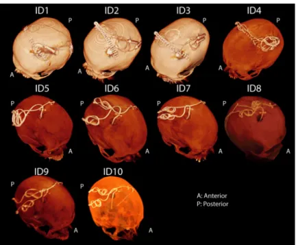
Postoperative CT images of ten patients who had undergone surgery for bilateral DBS implan-tation was used to extract lead trajectories (Fig3). The secondary use of imaging data for
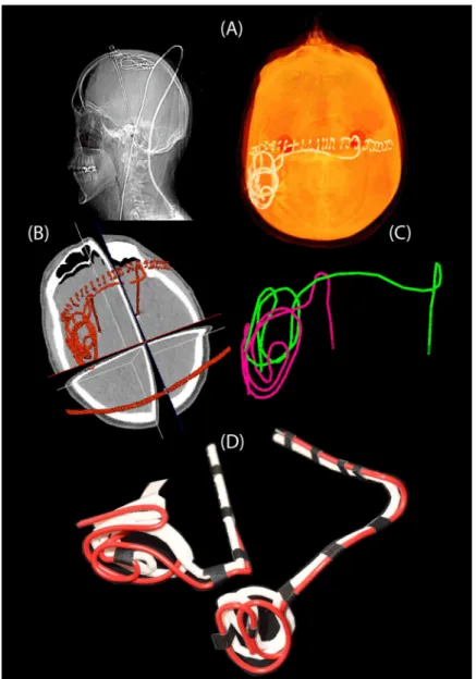
modeling and simulation was approved by the ethics review board of Massachusetts General Hospital. A total of 20 leads were constructed for measurements. Amira software (Thermo Fisher Scientific, Waltham MA) was used for image segmentation and construction of the pre-liminary 3D surface of the leads. First, a thresholding mask was applied to select the hyper dense DBS lead from CT images using Amira’s segmentation module (Fig 4A and 4B). Thresh-old values were selected manually on a case-by-case basis such that the resulting mask pro-duced a smooth continuous 3D surface. 3D lead surfaces were exported to a CAD tool (Rhino3D, Robert McNeal and Associates, Seattle, WA) in which lead trajectory lines were manually extracted, thickened (4mm diameter), and prepared for 3D printing (Fig 4C). Lead guides were then 3D printed out of polycarbonate plastic using a Fortus 360mc 3D printer (Stratasys, Eden Prairie, MN, USA). Two pieces of insulated wire (Ga 14, solid core, McMas-ter-Carr Elmhurst, IL) each 40 cm long with 1cm exposed tip were shaped around 3D printed guides to follow the left and right lead trajectories (Fig 4D). Wires were rigid enough to main-tain their shape once they were routed around the plastic guides and were detached from the guide before being implanted into the head phantom.
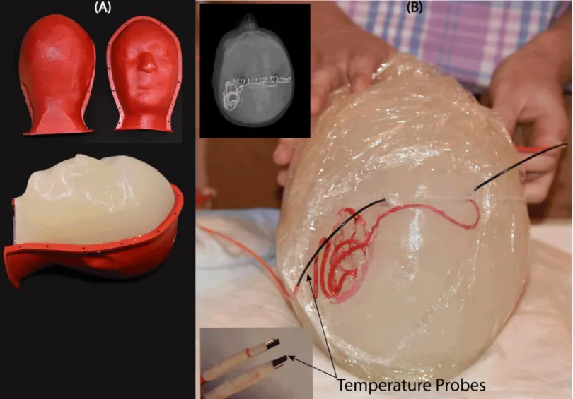
An anthropomorphic head phantom was designed and 3D-printed based on the structural MRI of a healthy volunteer. The mold was composed of two sagittal sections connected through a rim (Fig5A). Phantom dimensions were approximately 16 cm ear-to-ear and 27 cm from top of head to bottom of neck. The mold was filled with agarose-doped saline solution (5L water, 14g NaCl) through a hole at the bottom. A relatively high percentage of agarose (4%) was used which resulted in a semi-solid gel that could stand alone and support the implants. The electric properties of the gel were measured using a dielectric probe kit (85070E,
Fig 1. An overview of the reconfigurable MRI coil system. (A) View of constructed prototype and its finite element model.
(B) Electromagnetic simulations giving the magnitude of electric field E and maximum of 1g-averaged SAR on an axial plane passing through the center of the head. Simulations are performed with DBS leads of patient ID10 inFig 3. (C) Maximum 1g-averaged SAR is calculated inside a cubic area surrounding all electrode contacts. (D) The input power of the coil was adjusted to produce the mean B1+ = 2μT on a circular axial plane at the center of the head. The SAR was substantially reduced when the coil was rotated such that the majority of lead trajectory was contained within the region of low electric field.
https://doi.org/10.1371/journal.pone.0220043.g001
Fig 2. (A-B) The positioning of the rotating coil system on the patient’s table and the range of accessible rotating angles. (C) Phantom scanned with the body coil for
comparison. The body coil generated the same level of whole-head SAR as the rotating coil.
Agilent Technologies, Santa Clara, CA) and a network analyzer) to beσ = 0.47 S/m and εr= 77. Leads were implanted into the gel following the entrance point, angle, and trajectories as observed from CT images of the patient (Fig5B). Fluoroptic temperature probes (OSENSA, BC, Canada) were secured at the exposed tips of the wires for temperature measurements. A third probe was inserted to the center of the head phantom for background measurements.
RF exposure
Experiments were performed at a 1.5T Magnetom Avanto system using the rotating coils sys-tem as well as the built-in body coil for comparison. To better control the RF exposure, gradi-ent coils were disabled and a train of 1ms rectangular RF pulses were transmitted using the “rf_pulse” sequence from Siemens Service Sequence directory. Scan duration was set to 120 s
for both body coil and the rotating coil. The flip angle, however, was adjusted to make sure that all cases had the same level of power absorbed in the head phantom to allow for a fair com-parison. The absorbed power in the phantom was determined by subtracting the power dissi-pated in the coil and the reflected power from the forward power in the coil (assuming negligible radiation):
Pphantom¼Pforward Preflected Pcoil
loss ½1�
These values, registered as “TALES powers” in the scanner log file, are measured in real
time at a hardware component called Transmit Antenna Level Sensor (TALES) which resides between the output of the RF amplifier and the coil. In our case, an rf_pulse sequence with TR = 6.5 ms and flip angle = 180˚ generated 99 W power at the head phantom when transmit-ted with the body coil. For the rotating coil, the TR was kept the same but flip angle was
Fig 3. CT images of 10 patients operated for bilateral DBS implantation. For patients 1–4, the IPG was planned to
be implanted in the left pectoral pocket. Note that end segments of both leads are routed toward the left side of the head in these patients. In these cases, the left lead was labeled as ipsilateral and right lead was labeled contralateral when representing the temperature results in Figs6and7. For patients 5–10 the IPG was planned to be implanted in the right pectoral region, thus in these patients the right lead was labeled ipsilateral and left lead was labeled as contralateral.
https://doi.org/10.1371/journal.pone.0220043.g003
adjusted to 150˚ which generated 101 W power at the head phantom. Note that considering the weight of the phantom (~4kg), these values generated a global head SAR of ~25W/kg which is significantly higher than the FDA recommended a limit of 3.2 W/kg for clinical appli-cations. Such high SAR value was necessary to produce enough heating at the tips of the lead wires to be above the noise in all experiments.
Temperature measurements
At the start of each experiment, when the head phantom was at iso-center of the body coil, we measured the temperature rise at the tips of right and left implants by transmitting two-minute rf_pulse sequences using the body coil. Left and right leads were labeled as contralateral or ipsilateral depending on the IPG side. For patients 1–4, the IPG was planned to be implanted in the left pectoral pocket (seeFig 2, showing end segments of both leads routed toward the left side of the head). For these patients, the left lead was labeled as ipsilateral and right lead
Fig 4. Steps of image segmentation (A-B), 3D model construction (C), and 3D printed plastic guides (D). https://doi.org/10.1371/journal.pone.0220043.g004
was labeled contralateral. For patients 5–10 the IPG was planned to be implanted in the right pectoral region, thus in these patients the right lead was labeled ipsilateral and left lead was labeled as contralateral. After measurements with the body coil, the phantom was left for 15 minutes to cool down. Measurements with the rotating coil started with the coil at its default position (feed up,θ = 0˚). The rf_pulse protocol was transmitted for 2 minutes and
tempera-tures at the tips of ipsilateral and contralateral leads as well as the background probe were recorded. The coil was then rotated to the left at 20˚ increments until all accessible rotation angles from 0˚ to 140˚ were covered (seeFig2). The coil was consequently repositioned at 0˚ and rotated to the other direction to cover angles from 360˚-220˚. Depending on the heating, the phantom was left for 15–30 minutes between each experiment to return to baseline tem-perature. At the end of each experiment we added a few extra measurement points around the position that produced the minimal heating on each lead to better estimate the optimum posi-tion angle.
Fig 5. (A) Anthropomorphic head phantom based on MRI of a healthy volunteer (B) 3D printed DBS lead phantoms were used as a guide to shape wires in the form of
patient-derived trajectories. Wires were implanted into semi-solid anthropomorphic head phantoms with temperature probes attached to their tips for temperature measurement during MRI with the body coil and the rotating coil system.
https://doi.org/10.1371/journal.pone.0220043.g005
Measurement vs simulations
To use the rotating coil system in practice, it is necessary to be able to find the optimum rota-tion angle for each patient in a way that is safe and does not require pre-scan imaging with high-SAR sequences. One possible approach is to perform patient-specific simulations to esti-mate the vicinity of the optimum angle, and then fine-tune the positioning of the coil by mini-mizing the image artifact on low-SAR pre-scans that do not heat up the lead [39]. To have an estimation of how well simulations could predict measurement results, we simulated patient 10 in a rotating coil and calculated the maximum of 1g-averaged SAR around the tips of ipsi-lateral and contraipsi-lateral leads for a range of coil rotation angles. The birdcage coil was modeled as a low-pass coil with 16 legs and two end rings constructed from 13mm copper strips (σ =
5.8×10⁷S/m) and tuned to 64MHz, similar to the constructed prototype. The RF gradient
shield of the scanner was modeled as an open-ended cylindrical copper sheet (radius = 35cm, length = 110cm). A 50O coaxial cable was designed as the feed and connected to one of the legs over a matching port. DBS lead models were reconstructed from CT images and registered in a homogeneous head phantom. Model preparation and simulation setup were same as described in our previous works [20,28]. Briefly, DBS leads were composed of four cylindrical contacts (outer diameter = 1.27 mm, wall thickness = 150μm), connected through a solid straight central core (diameter = 260μm) and embedded in polyurethane insulation (diame-ter = 1.27 mm,σ = 10−10s/m,εr= 3.5 [40]). Electrode contacts were made of 90%:10%
plati-num-iridium (Pt:Ir,σ = 4×10⁶S/m) positioned 0.5 mm apart. The coil was then rotated around the head model with 11.25˚ increments (32 positions), and at each rotating angle the input power of the coil was adjusted to generate the B1+= 2μT on an axial circular plane below
elec-trode tips (Fig 1D). The 1g-averaged SAR was then recorded from two 2cmx2cmx2cm cubic areas surrounding ipsilateral and contralateral leads and its maximum value was registered for that rotation angle. Because we were interested in comparing the coil rotation angle corre-sponding to the simulated maximum SAR to the coil rotation angle correcorre-sponding to the mea-sured maximum temperature rise (and not the absolute values of SAR orΔT), we normalized all SAR values to the global maximum SAR value, and allΔT values to the global maximum temperature rise.
Results
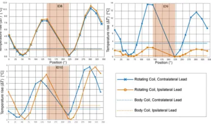
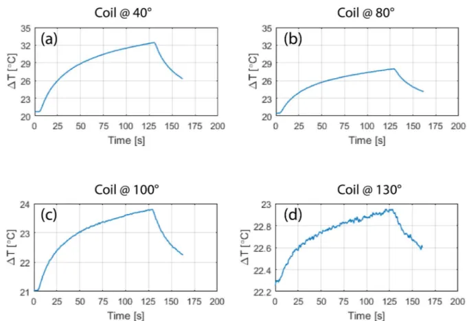
Fig 6andFig 7show the result of temperature measurements at the tips of ipsilateral and con-tralateral leads of patients 1–10 for the range of accessible coil rotation angles during 2-minute RF exposure at the global SAR level of 25 W/kg. For each patient, the temperature rise at the tips of the leads are also given when the built-in body coil was used (straight dashed lines).Fig 8gives the time evolution of temperature around the tip of the contralateral lead in patient 1 for four coil rotation angles at (a) 40˚, (b) 80˚, (c) 100˚, and (d) 230˚ as an example.
To quantify the performance of the reconfigurable coil to reduce the heating of implanted leads, we defined a factor calledheat reduction percentage or HRP for each lead and at each
coil rotation angle as:
HRP ¼100ðDTcp DTRBÞ
DTcp
½2�
whereΔTCPis the temperature rise at the tip of the lead at the end of the 2-minute measurement
with the built-in body coil andΔTRBis the temperature rise at the end of 2-minute measurement
with the rotating birdcage coil. A positive HRP at a rotation angleθ indicates that for the same
Fig 6. Temperature rise at the tips of ipsilateral and contralateral leads after 2 minutes of RF exposure. Red circles
show coil positions corresponding to temperature curves ofFig 8.
https://doi.org/10.1371/journal.pone.0220043.g006
Fig 7. Temperature rise at the tips of ipsilateral and contralateral leads after 2 minutes of RF exposure (continued).
https://doi.org/10.1371/journal.pone.0220043.g007
of the implanted wire compared to the body coil. In contrast, a negative HRP at an angleθ
indi-cates that the rotating coil positioned atθ generates more heating at the tip of the implanted
wire compared to the body coil when both coils generate the same level of global SAR.
Optimal rotation angle for single leads
Table 1gives the HRP values for ipsilateral and contralateral leads of each patient at two distinct coil rotation angles which minimized either the heating of ipsilateral lead or the heating of contra-lateral lead. Table entries highlighted green show the lead for which the heating was minimized. For example, in patient 9, coil atθ = 230˚ minimized the heating of ipsilateral lead (HRPIpsi= 97)
and coil atθ = 40˚ minimized the heating of contralateral lead (HRPcontra= 63). As it can be
observed fromTable 1(as well as Figs6and7), for each of the 20 leads there existed an optimum coil rotation angle that reduced the heating of the lead to a level well below the heating produced by the body coil. On average, a substantial heat reduction of 80%±19% was achieved for single leads. In 33% of cases (patients 5,7 and 8) the optimum rotation angles that minimized the heat-ing of ipsilateral and contralateral leads were the same. For the rest of patients, the optimal angles for ipsilateral and contralateral leads were different and in 40% of cases (patients 2,3,4, and 10) the rotation angle that minimized the heating at one lead increased the heating at the other one.
Optimal rotation angle for double leads
From the results of the previous section one can see that for most realistic bilateral DBS implants there is not an optimal coil rotation angle that maximally reduces the heating of both
Fig 8. Time evolution of temperature in the tissue at the tip of contralateral lead of patient 1 for the coil in four different rotational positions corresponding to red circles annotated inFig 6.
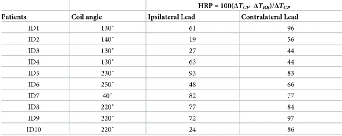
ipsilateral and contralateral leads. For all patients however, it was possible to find an interme-diate coil position that reduced the heating of both leads to a level below the heating produced by the body coil, albeit this position was not always optimum for each lead alone.Table 2
shows the rotation angle that maximized the value of HRPtotal= HRPipsi+HRPcontra. As it can
be observed from the table, for all ten patients we were able to reduce the heating of both ipsi-lateral and contraipsi-lateral leads to a level below the heating produced by the body coil. When optimized for bilateral leads, an average heat reduction factor of 65%±25% was achieved.
Simulations as a mean to estimate coil position
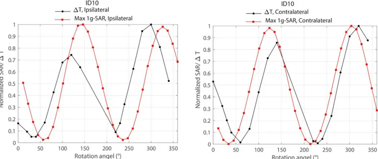
Fig 9shows the overlaid results of local SAR and temperature rise around ipsilateral and con-tralateral leads of patient 10 as a function of coil rotation angle. As it can be observed from the
Table 1. HPR values for ipsilateral and contralateral leads of patients 1–10.
HRP = 100(ΔTCP−ΔTRB)/ΔTCP
Patients Coil angle Ipsilateral Lead Contralateral Lead
ID1 130˚ 61 96 300˚ 33 97 ID2 340˚ 19 -91 300˚ -81 70 ID3 280˚ 95 -218 340˚ -149 87 ID4 100˚ 93 -104 340˚ -128 82 ID5 230˚ 93 83 ID6 100˚ 87 -39 240˚ 7 90 ID7 40˚ 82 77 ID8 220˚ 77 84 ID9 230˚ 97 19 40˚ 75 63 ID10 250˚ 95 -73 40˚ -60 74
For each patient, HPR is given for rotating angles that minimized the heating either at ipsilateral or contralateral lead.
https://doi.org/10.1371/journal.pone.0220043.t001
Table 2. HPR values for ipsilateral and contralateral leads of patients 1–10.
HRP = 100(ΔTCP−ΔTRB)/ΔTCP
Patients Coil angle Ipsilateral Lead Contralateral Lead
ID1 130˚ 61 96 ID2 140˚ 19 56 ID3 130˚ 27 44 ID4 130˚ 63 44 ID5 230˚ 93 83 ID6 250˚ 48 66 ID7 40˚ 82 77 ID8 220˚ 77 84 ID9 220˚ 72 97 ID10 220˚ 24 86
For each patient, HPR values are given for the rotating angle that maximized HRPipsi+HRPcontra.
https://doi.org/10.1371/journal.pone.0220043.t002
Fig, simulations could estimate the optimum rotation angle within 20˚ of accuracy. It is impor-tant to note however that another level of uncertainty was introduced by performing simula-tions on the models that were based on the original CT images of the patient, rather than on the models constructed from CT images of implemented leads in the head phantom used in measurement. Although for measurements we tried our best to implant the wires in the gel phantom following visual guidance from patient’s CT images, we could not replicate the exact positioning of the lead as happened in the patient. Numerical models on the other hand, repre-sented the exact lead orientation of the patient which explains the slight discrepancy between simulations and measurement results.
Discussion and conclusion
This work presents experimental results of temperature measurements at the tips of bilateral DBS leads during MRI using a new rotating coil system that can be adjusted for each patient to reduce the local heating of the implant. The idea of generating and steering electric-field free regions in MR transmit coils to reduce implant heating was originally introduced by Atalar’s group [25,32] and later adopted in studies that designed implant-friendly modes in parallel transmit volume coils at 3T [23,24,26,41]. Techniques based on tailoring the transmit pulse usually adopt a cumbersome simulation approach to determine the magnitude and phase of the signal at each transmit channel to shape the electric field in the region of interest (i.e., around the implant) while maintaining a user-defined threshold of B1homogeneity
through-out the sample. Although using a multi-channel transmit methodology allows more degrees of freedom for field tailoring, and thus could potentially achieve a better SAR reduction for com-plicated implant trajectories (e.g., multiple leads), such benefit comes with the drawback of rendering the technique complicated for application in clinic. The rotating coil system intro-duced here has the advantage of having a very simple setup, however such ease of operation comes at the expense of lack of control on the shape of the low electric field region. In other words, apart from“steering” the low E-field region by rotating the coil around patient’s head,
there is no other control on the shape and extend of this low field region. It is established that
Fig 9. Comparison of simulated maximum 1g-averaged SAR and measured temperature rise around ipsilateral and contralateral leads of patient 10. SAR
and temperature values were normalized to their corresponding maximum before overlaying the plots.
the SAR amplification at the tips of elongated implants depends on the coupling between the tangential component of the incident electric field and implanted wires [34,35,42]. As implanted DBS leads have complex trajectories consisting of segments that cannot be con-tained in one plane (seeFig3), it is important to assess the performance of any SAR-reducing strategy in models based on real patient data. This work presents the first report of such assess-ment, demonstrating promising results in possibility of reducing the SAR at the tips of both left and right DBS leads to levels below the SAR generated by standard body coils. It should be noted however, that the current study is limited to the assessment of heating at the tips of DBS leads in isolation, i.e., prior to their connection to the extension cables and the implanted pulse generator; therefore, the results presented here should not be the extended to other configura-tions. Further investigation is necessary to establish the efficacy of the technique in a fully implanted system.
FromTable 1it can be observed that for patients 5, 7 and 8 the optimum coil rotation angle that minimized the SAR at the tips of right and left leads was the same. A closer look at the lead trajectory in these patients (Fig 1) reveals that ipsilateral and contralateral lead trajectories are routed such that their trajectories are substantially parallel in this case. We recently showed that it is possible to implement simulation-driven instructions in the implantation of extracra-nial portion of DBS leads during the surgery to reduce the SAR, without requiring additional equipment or adding to the surgical time [43]. Therefore, surgeons can be instructed to subcu-taneously rout the leads such that their trajectories be maximally parallel. This will allow the reconfigurable coil system to perform as efficiently in the case of patients with bilateral leads as it does for unilateral implants. Instructing surgeons to follow a lead management strategy can also reduce the uncertainty in the overall shape of extracranial trajectory of the lead. Unlike the meticulously planned intracranial lead trajectory, for which almost every neurosurgeon follows textbook guidelines to choose the entry point on the skull and the angle of penetration to the target nuclei, there are no rules or guidelines for the placement of extra cranial portions of the leads. As a result, there is a substantial patient-to-patient variation in the trajectory of extracranial portion of the leads with many cases exhibiting abrupt changes in the orientation of lead segments. This increases the sensitivity of coil positioning, as small deviations from the optimum angle could cause parts of the lead to fall out of low electric field region.
Our preliminary results comparing simulation results and measurements indicated that patient-specific models are a viable choice to predict the whereabout of the optimum coil angle. Once this initial angle is predicted, the position can be fine-tuned by minimizing the image artifact using low-SAR pre-scans that do not heat up the lead. More work is needed however, to quantify the agreement of numerical models with measurements and to devise detailed strategies to fine tune the coil position for each patient.
Acknowledgments
This work was supported by the NIH grants R03EB024705 and R00EB021320.
Author Contributions
Conceptualization: Laleh Golestanirad, Boris Keil, Lawrence L. Wald. Data curation: Laleh Golestanirad, Ehsan Kazemivalipour, Sean Downs. Formal analysis: Laleh Golestanirad.
Funding acquisition: Laleh Golestanirad.
Investigation: Laleh Golestanirad, Ehsan Kazemivalipour, Julie Pilitsis.
Methodology: Laleh Golestanirad, Boris Keil. Project administration: Laleh Golestanirad.
Resources: John Kirsch, Julie Pilitsis, Lawrence L. Wald. Validation: Laleh Golestanirad, John Kirsch.
Writing – original draft: Laleh Golestanirad, Behzad Elahi.
Writing – review & editing: Laleh Golestanirad, Behzad Elahi, Julie Pilitsis.
References
1. US Food and Drug Administration (FDA). FDA executive summary: Medtronic Activa Neurostimulator for Dystonia Treatmenthttps://www.fda.gov/downloads/AdvisoryCommittees/
CommitteesMeetingMaterials/PediatricAdvisoryCommittee/UCM543856.pdf, 2017.
2. US Food and Drug Administration (FDA). Medtronic (ACTIVA) Deep Brain Stimulation for OCD Ther-apy.https://www.accessdata.fda.gov/scripts/cdrh/cfdocs/cfhde/hde.cfm?id=H050003, 2009. 3. US Food and Drug Administration (FDA). Medtronic DBS system for epilepsyhttps://www.accessdata.
fda.gov/cdrh_docs/pdf/P960009S219a.pdf, 2018.
4. Ackermans L, Temel Y, Visser-Vandewalle VJN. Deep brain stimulation in Tourette’s syndrome. 2008; 5(2):339–44.
5. Schrock LE, Mink JW, Woods DW, Porta M, Servello D, Visser-Vandewalle V, et al. Tourette syndrome deep brain stimulation: a review and updated recommendations. 2015; 30(4):448–71.
6. Holtzheimer PE, Kelley ME, Gross RE, Filkowski MM, Garlow SJ, Barrocas A, et al. Subcallosal cingu-late deep brain stimulation for treatment-resistant unipolar and bipolar depression. 2012; 69(2):150–8. 7. Corripio I, Sarro´ S, McKenna PJ, Molet J, A´ lvarez E, Pomarol-Clotet E, et al. Clinical improvement in a
treatment-resistant patient with schizophrenia treated with deep brain stimulation. 2016; 80(8):e69– e70.
8. Sartorius A, Kiening KL, Kirsch P, von Gall CC, Haberkorn U, Unterberg AW, et al. Remission of major depression under deep brain stimulation of the lateral habenula in a therapy-refractory patient. 2010; 67 (2):e9–e11.
9. Malone DA Jr, Dougherty DD, Rezai AR, Carpenter LL, Friehs GM, Eskandar EN, et al. Deep brain stim-ulation of the ventral capsule/ventral striatum for treatment-resistant depression. 2009; 65(4):267–75. 10. Golestanirad L, Elahi B, Graham SJ, Das S, Wald LLJCJoNS. Efficacy and safety of pedunculopontine
nuclei (PPN) deep brain stimulation in the treatment of gait disorders: a meta-analysis of clinical studies. 2016; 43(1):120–6.
11. Tagliati M, Jankovic J, Pagan F, Susatia F, Isaias IU, Okun MS. Safety of MRI in patients with implanted deep brain stimulation devices. Neuroimage. 2009; 47:T53–T7.https://doi.org/10.1016/j.neuroimage. 2009.04.044PMID:19376247
12. Moeschler SM, Sanders RA, Hooten WM, Hoelzer BCJNTatNI. Spinal cord stimulator explantation for magnetic resonance imaging: a case series. 2015; 18(4):285–8.https://doi.org/10.1111/ner.12254 PMID:25345833
13. Shellock FG, Fischer L, Fieno DS. Cardiac pacemakers and implantable cardioverter defibrillators: in vitro magnetic resonance imaging evaluation at 1.5-tesla. Journal of Cardiovascular magnetic reso-nance. 2007; 9(1):21–31.https://doi.org/10.1080/10976640600897237PMID:17178677
14. Sommer T, Naehle CP, Yang A, Zeijlemaker V, Hackenbroch M, Schmiedel A, et al. Strategy for Safe Performance of Extrathoracic Magnetic Resonance Imaging at 1.5 Tesla in the Presence of Cardiac Pacemakers in Non–Pacemaker-Dependent Patients A Prospective Study With 115 Examinations. Cir-culation. 2006; 114(12):1285–92.https://doi.org/10.1161/CIRCULATIONAHA.105.597013PMID: 16966587
15. Baker KB, Tkach J, Hall JD, Nyenhuis JA, Shellock FG, Rezai AR. Reduction of magnetic resonance imaging-related heating in deep brain stimulation leads using a lead management device. Neurosur-gery. 2005; 57(4):392–7.
16. Finelli DA, Rezai AR, Ruggieri PM, Tkach JA, Nyenhuis JA, Hrdlicka G, et al. MR imaging-related heat-ing of deep brain stimulation electrodes: in vitro study. American Journal of Neuroradiology. 2002; 23 (10):1795–802. PMID:12427641
17. Rezai AR, Finelli D, Nyenhuis JA, Hrdlicka G, Tkach J, Sharan A, et al. Neurostimulation systems for deep brain stimulation: In vitro evaluation of magnetic resonance imaging–related heating at 1.5 tesla. Journal of Magnetic Resonance Imaging. 2002; 15(3):241–50. PMID:11891968
18. Rezai AR, Phillips M, Baker KB, Sharan AD, Nyenhuis J, Tkach J, et al. Neurostimulation system used for deep brain stimulation (DBS): MR safety issues and implications of failing to follow safety recom-mendations. Investigative radiology. 2004; 39(5):300–3. PMID:15087724
19. McElcheran C, Golestanirad L, Iacono M, Wei P-S, Yang B, Anderson K, et al. Numerical Simulations of Realistic Lead Trajectories and an Experimental Verification Support the Efficacy of Parallel Radiofre-quency Transmission to Reduce Heating of Deep Brain Stimulation Implants during MRI. 2019; 9 (1):2124.
20. Golestanirad L, Kirsch J, Bonmassar G, Downs S, Elahi B, Martin A, et al. RF-induced heating in tissue near bilateral DBS implants during MRI at 1.5 T and 3T: The role of surgical lead management. Neuro-Image. 2019; 184:566–76.https://doi.org/10.1016/j.neuroimage.2018.09.034PMID:30243973 21. Golestanirad L, Angelone LM, Kirsch J, Downs S, Keil B, Bonmassar G, et al. Reducing RF-Induced
Heating Near Implanted Leads Through High-Dielectric Capacitive Bleeding of Current (CBLOC). IEEE Transactions on Microwave Theory and Techniques. 2019; 67(3):1265–73.
22. Golestanirad L, Rahsepar AA, Kirsch JE, Suwa K, Collins JC, Angelone LM, et al. Changes in the spe-cific absorption rate (SAR) of radiofrequency energy in patients with retained cardiac leads during MRI at 1.5 T and 3T. Magnetic resonance in medicine. 2018.
23. McElcheran CE, Yang B, Anderson KJ, Golestanirad L, Graham SJ. Parallel radiofrequency transmis-sion at 3 tesla to improve safety in bilateral implanted wires in a heterogeneous model. Magnetic reso-nance in medicine. 2017; 78(6):2406–15.https://doi.org/10.1002/mrm.26622PMID:28244142 24. McElcheran CE, Yang B, Anderson KJ, Golenstani-Rad L, Graham SJ. Investigation of Parallel
Radio-frequency Transmission for the Reduction of Heating in Long Conductive Leads in 3 Tesla Magnetic Resonance Imaging. PLoS One. 2015; 10(8):e0134379.https://doi.org/10.1371/journal.pone.0134379 PMID:26237218
25. Eryaman Y, Akin B, Atalar E. Reduction of implant RF heating through modification of transmit coil elec-tric field. Magnetic resonance in medicine. 2011; 65(5):1305–13.https://doi.org/10.1002/mrm.22724 PMID:21500259
26. Eryaman Y, Guerin B, Akgun C, Herraiz JL, Martin A, Torrado-Carvajal A, et al. Parallel transmit pulse design for patients with deep brain stimulation implants. Magnetic resonance in medicine. 2014; 73 (5):1896–903.https://doi.org/10.1002/mrm.25324PMID:24947104
27. Golestanirad L, Angelone LM, Iacono MI, Katnani H, Wald LL, Bonmassar G. Local SAR near deep brain stimulation (DBS) electrodes at 64 MHz and 127 MHz: A simulation study of the effect of extracra-nial loops Magnetic Resonance in Medicine 2016; 88(4):1558–65.
28. Golestanirad L, Keil B, Angelone LM, Bonmassar G, Mareyam A, Wald LL. Feasibility of using linearly polarized rotating birdcage transmitters and close-fitting receive arrays in MRI to reduce SAR in the vicinity of deep brain simulation implants. Magnetic resonance in medicine. 2017; 77(4):1701–12. https://doi.org/10.1002/mrm.26220PMID:27059266
29. Golestanirad L, Iacono MI, Keil B, Angelone LM, Bonmassar G, Fox MD, et al. Construction and model-ing of a reconfigurable MRI coil for lowermodel-ing SAR in patients with deep brain stimulation implants. Neuro-image. 2017; 147:577–88.https://doi.org/10.1016/j.neuroimage.2016.12.056PMID:28011252 30. Ondo W, Almaguer M, Jankovic J, Simpson RK. Thalamic deep brain stimulation: comparison between
unilateral and bilateral placement. Archives of Neurology. 2001; 58(2):218–22.https://doi.org/10.1001/ archneur.58.2.218PMID:11176959
31. Taba HA, Wu SS, Foote KD, Hass CJ, Fernandez HH, Malaty IA, et al. A closer look at unilateral versus bilateral deep brain stimulation: results of the National Institutes of Health COMPARE cohort. Journal of neurosurgery. 2010; 113(6):1224–9.https://doi.org/10.3171/2010.8.JNS10312PMID:20849215 32. Eryaman Y, Turk EA, Oto C, Algin O, Atalar E. Reduction of the radiofrequency heating of metallic
devices using a dual-drive birdcage coil. Magnetic Resonance in Medicine. 2012.
33. Calcagnini G, Triventi M, Censi F, Mattei E, Bartolini P, Kainz W, et al. In vitro investigation of pace-maker lead heating induced by magnetic resonance imaging: role of implant geometry. Journal of Mag-netic Resonance Imaging. 2008; 28(4):879–86.https://doi.org/10.1002/jmri.21536PMID:18821629 34. Yeung CJ, Susil RC, Atalar E. RF heating due to conductive wires during MRI depends on the phase distribution of the transmit field. Magnetic resonance in medicine. 2002; 48(6):1096–8.https://doi.org/ 10.1002/mrm.10310PMID:12465125
35. Park SM, Kamondetdacha R, Nyenhuis JA. Calculation of MRI-induced heating of an implanted medical lead wire with an electric field transfer function. Journal of Magnetic Resonance Imaging. 2007; 26 (5):1278–85.https://doi.org/10.1002/jmri.21159PMID:17969143
36. Nordbeck P, Ritter O, Weiss I, Warmuth M, Gensler D, Burkard N, et al. Impact of imaging landmark on the risk of MRI-related heating near implanted medical devices like cardiac pacemaker leads. Magnetic resonance in medicine. 2011; 65(1):44–50.https://doi.org/10.1002/mrm.22592PMID:20806352 37. Mattei E, Triventi M, Calcagnini G, Censi F, Kainz W, Mendoza G, et al. Complexity of MRI induced
heating on metallic leads: experimental measurements of 374 configurations. Biomedical engineering online. 2008; 7(1):11.
38. Hoult D. The principle of reciprocity in signal strength calculations—a mathematical guide. Concepts in Magnetic Resonance. 2000; 12(4):173–87.
39. Eryaman Y, Kobayashi N, Moen S, Aman J, Grant A, Vaughan JT, et al. A simple geometric analysis method for measuring and mitigating RF induced currents on Deep Brain Stimulation leads by multi-channel transmission/reception. 2019; 184:658–68.
40. Elwassif MM, Kong Q, Vazquez M, Bikson M. Bio-heat transfer model of deep brain stimulation-induced temperature changes. Journal of neural engineering. 2006; 3(4):306. https://doi.org/10.1088/1741-2560/3/4/008PMID:17124335
41. Clare McElcheran, Golestanirad L, Graham S, editors. Reduced Heating of Implanted Electrical Con-ductors Using Parallel Radiofrequency Transmission. Joint Annual Meeting of the International Society of Magnetic Resonace in Medicin (ISMRM); 2014; Milan, Italy.
42. Nitz WR, Oppelt A, Renz W, Manke C, Lenhart M, Link J. On the heating of linear conductive structures as guide wires and catheters in interventional MRI. Journal of Magnetic Resonance Imaging. 2001; 13 (1):105–14. PMID:11169811
43. Golestanirad L, Pilitsis J, Martin A, Larson P, Keil B, Bonmassar G, et al., editors. Variation of RF heat-ing around deep brain stimulation leads durheat-ing 3.0 T MRI in fourteen patient-derived realistic lead mod-els: The role of extracranial lead management. 25th Annual Meeting of the International Sosciety of Magnetic Resonance in Medicine, 2017.