REVIEW
Cite this:Nanoscale, 2019, 11, 11402
Received 25th April 2019, Accepted 21st May 2019 DOI: 10.1039/c9nr03533h rsc.li/nanoscale
LEDs using halide perovskite nanocrystal emitters
Fei Yan
aand Hilmi Volkan Demir
*
a,b,cThe emerging family of lead–halide perovskite (LHP) nanocrystal emitters has shown impressive achieve-ments in solid-state light-emitting applications. With luminous efficiency comparable to that of organic light-emitting diodes, LHP light-emitting diodes (PeLEDs) have demonstrated a wide colour gamut with high colour purity and a widely tunable range of emissive wavelengths across the whole visible range. Herein, the understanding of LHP nanocrystals in light emission and the resulting PeLEDs are reviewed. Additionally, key features of LHP nanocrystal emitters applied in PeLEDs and guidelines towards realizing high-performance devices are discussed.
1.
Introduction
From rock painting to augmented reality, numerous display technologies have been developed to illustrate the colourful world. Intuitive drawing is the predominant method of vision for apperceiving information from the world around us. In such a messaging process, the truthfulness of information, including colour data, is essential. Therefore, various full-colour display technologies from cathode-ray tubes to liquid-crystal displays (LCDs) and then to flexible organic light-emit-ting diodes (OLEDs) have emerged. However, no available display technologies can fully cover the natural colour gamut as recognized by the National Television System Committee (NTSC) TV colour standard (Fig. 1a). Recently, highly efficient lead–halide perovskites (LHPs) have emerged as a new kind of solid-state emitters, and the resulting perovskite light-emitting diodes (PeLEDs) have achieved performance levels comparable to OLEDs and cadmium selenide (CdSe) colloidal quantum dot light-emitting diodes (QLEDs), including high luminous efficiency, low cost, large area, and flexibility.1–24
Most efficient emitters used in PeLEDs are LHP nanocrys-tals (NCs), for which films reach a near-unity photo-luminescence quantum yield (PLQY) by facilitating exciton radiative recombination;20,25–30 the resulting PeLEDs have achieved an external quantum efficiency (EQE) of over 20%.21–24 Moreover, because of the high colour purity and
broad emissive wavelength range, PeLEDs demonstrate an un-precedented colour gamut, which almost completely cover the CIE 1931 colour spaces (Fig. 1a and b).31–34
The LHP NCs can be indicated in a chemical formula (R)2(A)n−1BnX3n+1, where n =∞ corresponds to the normal 3D
LHPs with chemical formula ABX3 and n = 1 corresponds to
the monolayer 2D LHP R2ABX4(Fig. 1c).35Normally site A is
an organic cation of formamidinium (FA), methylammonium (MA) or Cs+; site B is Pb2+; site X is Cl−, Br−, or I−; and R is a molecule spacer in the 2D LHPs.35–39 The corner-sharing [PbX6]4−octahedra are the core of LHPs, which surround the
cations to compose LHPs with a 3D structure or sandwiched by a molecular spacer to form LHPs with a 2D structure.35–39 By changing the halide component from iodine to chlorine, the emissive spectra can be adjusted significantly from the near infrared to near ultraviolet (Fig. 1b).35–39
In this review, we summarized up-to-date achievements for PeLEDs using LHP NCs, also including quantum dots (QDs) and nanoplatelets (NPLs) with strong quantum confinement, we also present insights on device work, including physics of light emission and device fabrication, and guidelines for high performance PeLEDs for the readers. We envision that this review will trigger some subsequent works or new possibilities for PeLEDs and other relative subfields.
2.
Fundamental properties of LHP
nanocrystals as e
fficient emitters
With a low binding energy of dozens of meV caused by a large dielectric constant, the Wannier–Mott excitons formed in LHPs dissociate into free charge carriers with a high possi-bility at room temperature, which is one merit for superior per-formance photovoltaics.40–43 With the high electron and hole mobility in LHPs, the charge carriers are almost free with
neg-aLUMINOUS! Centre of Excellence for Semiconductor Lighting and Displays, TPI-The Photonics Institute, School of Electrical and Electronic Engineering, Nanyang Technological University, 639798, Singapore.
E-mail: [email protected]
bDivision of Physics and Applied Physics, School of Physical and Mathematical Sciences Nanyang Technological University, 639798, Singapore
cDepartment of Electrical and Electronics Engineering, Department of Physics, UNAM–Institute of Materials Science and Nanotechnology, Bilkent University, Ankara 06800, Turkey
View Article Online
ligible wavefunction overlap.44,45Generally, the radiation from LHP polymorph emitters mainly stems from a slow bimolecu-lar recombination with an intrinsic constant determined by the hole–electron cross-section and group velocities (Fig. 2a).46,47Similarly, it is supposed that the exciton formed by injected carriers (in electrical excitation) also dissociate back to free charge carriers with a high possibility, which limits the luminescence efficiency of PeLEDs. In LHP NCs with dimensions in the range of several nanometres to tens of nanometres, the charge carriers are confined in a small-sized domain by the grain boundary and passivate ligands, which increases the exciton biding energy by up to approximately 300 meV.48–50 Owing to the comparable effective mass of the hole and electron, the confinement of their wavefunctions are almost equal, which facilitates efficient first-order exciton recombination dominating the two-order bimolecular recom-bination (Fig. 2a).20,51–56
As a highly ionic compound, normally, LHP NCs are highly crystalline with a low level of defects.57The electronic band gap for LHP NCs is determined by the difference between the antibonding orbitals of Pb6s–Xnpcouplings (bottom of
conduc-tion band) and antibonding orbitals of Pb6p–Xnp couplings
(top of valence band) (Xnp: Cl3p, Br4p, I5p).57–59 In addition,
their bonding orbitals are deeper within the valence band (Fig. 2b).57–59 Therefore, such a special electronic band struc-ture results in an intrinsic defect tolerance by leaving a clean band gap free of deep trap states (Fig. 2b), which is unlike the band gap formed by the antibonding conduction band and bonding valence band in conventional semiconductors.57–59
Thus, in virtue of a low level of trap-mediated non-radiative recombination, the LHP NCs exhibit high PLQY emission in colloidal solution even without any passivation of ligands.33,58,61,62Furthermore, the surface defects in LHP NCs can be effectively passivated by capping ligands, which enhances the PLQY of LHP NCs by up to near unity.60,63–66
Although the LHP NCs exhibit an efficient exciton emission with a high exciton binding energy of up to approximately 300 meV, which is close to the value for an organic molecule exciton, the excitons, however, are not unambiguously of the Frenkel or Wannier type.48–50,67it is believed that the exciton is a hybrid of the Frenkel and Wannier types in 2D structure LHPs.67Unlike organic molecule exciton emission that follows a spin selection rule, by virtue of strong spin-orbital coupling, which is supposed to be related to the heavy elements contained therein, the spin angular momentum conservation is not a transition selection rule that limits the luminous efficiency of LHP NCs.68 Moreover, unlike other inorganic
semiconductors, e.g., CdSe QDs, for which the lowest state of the exciton is dipole-forbidden, the emission from CsPbX3
NCs was demonstrated to originate from the lowest state of the exciton.68With three bright triplet states from four sublevels, the CsPbX3 NCs indicate a fast exciton radiation (Fig. 2c).68
Therefore, the LHP NCs demonstrate near unity quantum yield in both optical and electrical excitations.21–24
Due to the predominant role of Pb and X in determining the conduction band and valence band, respectively, the band gap can be tuned by changing the halogen species from Cl to I, leading to an adjustable emission wavelength through the
Fig. 1 (a) CIE chromaticity coordinates (dark points) for CsPbX3LHP NCs emission compared with commercialized LCD TVs (dashed white line) and
colour standards for TVs (NTSC) (solid white line).33Copyright © 2017, American Association for the Advancement of Science. (b) PL spectra for LHP NCs with different halide components.33Copyright © 2017, American Association for the Advancement of Science. (c) Schematic and bandgap of quasi-2D perovskite with a varying number of layers.35Copyright © 2018, Springer Nature. (d) Photographs of the LHP NPL suspensions under UV light.39Copyright © 2015 American Chemical Society.
whole visible range.57–59 Furthermore, using mixed halogen species to take site X, the emissive wavelength of LHPs can be flexibly controlled in the visible range (Fig. 1b).35,69–73 Compared to OLEDs and QLEDs, the LHP NCs and their PeLEDs demonstrate a much narrower linewidth for the emis-sion band.1–24 In hybrid LHPs with polar bonds, the narrow emissive band is believed to be mainly determined by the Fröhlich interaction between longitudinal optical phonons and charge carriers.74–76 Moreover, owing to the great defect tolerance of LHP NCs, the broadening of the emission spec-trum induced by traps is at a negligible level.58,59,77These fea-tures endow the LHP NCs with a high colour purity, which is another essential characteristics for a full colour display. Combining the flexible tunability of the emission wavelength through the whole visible range and high colour purity, the LHP NCs demonstrate a broad colour gamut, which almost overlaps the whole CIE 1931 colour space (Fig. 1a).31–33 Though the phase separation in LHP NCs with a mixed halide caused by ion migration results in a low stability for the emis-sion spectrum under electrical excitation,78–80 the RGB primary colour LHP NCs with a single halide exhibit stable EL spectra, which can be used to compose almost all target colours in the visible range (Fig. 1a).31–33
Bromide-based green and iodide-based red PeLEDs have achieved comparable EQE values as OLEDs and QLEDs.21–24
However, chloride-based blue LHP NCs still present a low luminous efficiency level in PeLEDs, for which the underlying reasons are the low intrinsic luminous efficiency and emission shift caused by phase separation under electrical excitation.35,78,81 With a small exciton Bohr radius, which is close to the dimension of the [PbBr6]4− octahedral cell, it is
difficult to obtain a qualified blue emission from 3D APbBr3
NCs with strong quantum confinement by controlling the particle size. Alternatively, APbBr3 multilayer NPLs with
strong quantum confinement can emit qualified blue light, as required for the blue component in a full colour display.35,82–84 By controlling the amount of [PbBr6]4− in the
layers, the emission colour from LHP NPLs can be adjusted from a deep blue to sky blue (Fig. 1d),35,82–84and due to the quantized amount of [PbX6]4− cell, it is easy to obtain a high
mono-dis-persion of LHP NCs, resulting in a narrow emissive spectrum. With the large polaron having minimized charge carrier scattering with defects, other charge carriers, and longitudinal optical phonons, LHP NCs exhibit high carrier mobility even in nanocrystals with confinement generated by the grain boundary and passivated ligands (Fig. 2d).20,85With small and comparable effective masses,56generally, the high hole
mobi-lity is comparable to that for electrons, which is also an impor-tant merit for achieving balanced charge carriers in the recom-bination zone of efficient PeLEDs (Fig. 2d).20,85However, such
Fig. 2 (a) Photon-injected charge carrier density dependence of the initial-time PL intensity (IPL(t = 0)).20Copyright © 2018 American Chemical
Society. (b) Schematic of the band structure and defect-tolerant electronic structure of LHPs.33Copyright © 2017 American Association for the Advancement of Science. (c) The expectedfine structure for the CsPbBr3exciton. The exciton splits into three bright states and a higher-energy
dark state.68Copyright © 2018, Springer Nature. (d) Mobility levels for the electron and hole derived from afield-effect transistor using MAPbBr 3
PeNCsfilm as the active layer.20Copyright © 2018 American Chemical Society. (e) PLQY as a function of the photon-injected charge carrier
high charge carrier transport involves electron-ion mixed con-duction, and directional ion-migration driven by the external electrical field leads to the degradation of LHP NCs.86,87
3.
Classi
fication of LHP nanocrystal
emitters
Although defects can be tolerated in LHPs, the non-radiative losses are still present at a substantial level, which suggests that un-neglected deep states exist in the bandgap (Fig. 2e). Such traps quench the luminescence through a first-order Shockley–Read–Hall non-radiative recombination at a compar-able rate to the exciton radiative process.20,40,42 Therefore, most LHP nanostructured emitters are crystalline surrounded by passivating ligands to minimize trap states.10–24 Although having similar components and formulae, LHP NCs with different structures, e.g., 3D and 2D, and morphology exhibit some individual features in terms of light emission.31–33 In addition, LHP NC films prepared in colloidal solution also demonstrate some differences compared to a film deposited in situ using a precursor solution.20–24,35
Normally, LHPs NCs have a 3D structure, which is similar to the bulky counterpart. By decreasing the dimension of the LHP NCs to a size comparable to the exciton Bohr radius, the quantum confinement effect emerges, and with strong quantum confinement the emission from LHP NCs exhibits a significant blueshift,21,88even to the blue range.35,82However, as the size of the exciton Bohr radius is comparable to the [PbX6]4−cell, it is difficult to precisely control the particle size
in 3D structure LHP QDs, which may lead to a broadening of the emissive spectrum.21,88 Due to the small size and light weight of LHP QDs, post-treatments, e.g., purification and con-centration, of the primary colloidal solution becomes difficult.
Alternatively, by decreasing the layer number for the [PbX6]4−cell, the emission from LHP NPLs also exhibits a
blue-shift with enhancement of quantum confinement. With a thickness of approximately 1 nm, monolayer LHP NPLs demonstrate an emission with a significant blueshift of approximately 400 meV compared to the 3D counterparts (Fig. 1c and d).82In addition, as the amount of [PbX6]4−layer
sandwiched by molecule spacers in LHP NPLs is quantized, the emission spectra can be adjusted more precisely compared to the LHP QDs.35,39,82–84,89–91Similar to the 2D counterparts, the LHP NPLs also show a better stability by protecting the [PbX6]4−core against ambient moisture and oxygen; however,
the interlayer charge carrier transport also becomes more difficult in LHP NPLs compared to 3D LHP NCs.35,39,82–84,89–91 Moreover, due to the 2D exciton feature and the diminished dielectric screening, the radiation from excitons in LHP NPLs is faster compared to the 3D LHP NCs.68
Alternatively, in situ fabrication using precursor solution is another approach for depositing LHP NCs films with the assist-ance of passivating ligands. Similarly, some matrix polymers can be mixed into the precursor solution for controlling the NC dimensions during the film deposition (Fig. 3a and b).92
With the consideration of environmental friendliness, lead-free perovskite emitters using Sn, Ge, Sb, In, Ag, and Bi instead of Pb with an electron structure or crystallographic structure that replicates halide perovskites have been studied.93–97 A3B2X9 halide perovskites give efficient emission
from the blue to UVA, which can be regarded as potential blue emitters for PeLEDs.98,99With a broad-band spectrum, a lead-free double perovskite Cs2Ag0.60Na0.40InCl6 exhibits a warm
white emission with a PLQY of approximately 90% (Fig. 3c), which suggests that white-colour PeLEDs with a simple struc-ture are possible.97 However, so far, lead-based perovskite emitters have dominated the highest performance in PeLEDs.21–24,93–99
4.
Key features of LHP nanocrystals
in LEDs
As an ionic compound, most LHP emissive layers, including the nanocrystal emitter film, in PeLEDs have been deposited using solution processing, which constrains the design of the device structure and the adoption of other functional layer materials. The deposited film must be tough enough against subsequent film fabrication; also a lower surface tension solu-tion is required for good wetting onto the substrate. Due to the highly ionic bonding of the LHPs, generally, a solvent with high dielectric constant, such as alcohol, is excluded from device fabrication, as it can damage LHPs.57,100
Due to the low lying energy levels of LHP NCs, there is a high energy barrier for hole injection into the emissive layer (Fig. 3d).20–23Due to the dominating role of X in determining the valence band, by changing the halide from iodide to chlor-ide, the extension of the band gap mainly occurs to the valence band, leading to a higher barrier for hole injection (Fig. 2b).57–59 Sometimes, a buffering layer can be used to increase hole injection.16,21As the directional migration of ion species inside a LHP layer is driven by the applied electrical field, p-type and n-type doping layers are formed at corres-ponding interfaces, which facilitates charge carrier injection into the LHP layer (Fig. 3e).87,101That is why some PeLEDs can be driven by a low voltage even without any assistance of hole injection layers (Fig. 4a).20,22,101 However, such low driving voltage is mostly accompanied by the shrinking of the LHP layers due to the decomposition of emitters, leading to a drop in the luminous efficiency and short device operation lifetime.87,101
The PLQY of LHP NC films plays a major role in determin-ing the maximum EQE that can be reached by the resultdetermin-ing PeLEDs. To suppress the trap-mediated non-radiative recombi-nation, high-ratio ligands are generally required for passivating the surface defects in LHP NCs, which also ensures good stabi-lity of the colloidal solution by preventing aggregation of the LHP NCs and smoothening the morphology of the resulting emissive film.1–16,20–23Similarly, for in situ deposition using a precursor solvent, high-ratio ligands are also used for control-ling the LHP NC size and film quality.35However, most
passi-Fig. 3 SEM image of (a) MAPbBr3NCs only, (b) 1/2 polyimide/MAPbBr3on a PEDOT:PSSfilm. Inset in (b) shows an enlarged image of a 1/2
polyi-mide/MAPbBr3 film.92 Copyright © 2015 American Chemical Society. (c) Luminosity function and photoluminescence spectra for
Cs2Ag0.60Na0.40InCl6measured at different temperatures.97Copyright © 2018 Springer Nature. (d) Energy level alignment for a PeLED.16Copyright ©
2016 American Chemical Society. (e) Distribution of ions in a pristinefilm, a film under an external electrical field, and a relaxed film after removal of the bias.101Copyright © 2017 American Chemical Society.
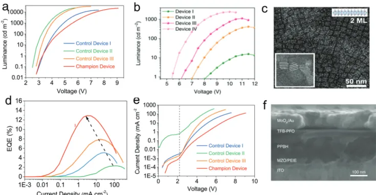
Fig. 4 (a) Luminance–voltage dependence for devices using LHP NC emitters.20Copyright © 2018 American Chemical Society. (b) Luminance–
voltage dependence for devices using LHP NPL emitters.35Copyright © 2018, Springer Nature. (c) 2 monolayer LHP NPLs and stacked structure
(inset).82Copyright © 2018 American Chemical Society. (d) EQE-current density characteristics and (e)I–V curves for PeLEDs with MAPbBr 3NC
emitters.20Copyright © 2018 American Chemical Society. (f ) Cross-sectional scanning electron microscopy image of the LED structure using a
vating ligands, such as oleylamine, are insulating for charge carrier injection into the surrounding LHP NCs during electri-cal excitation due to the long-chain alkyl.1–30
In LHP NPLs, the layer-by-layer structure of LHP NPLs sand-wiched by a molecule spacer also blocks the vertical charge carrier transport, which leads to a much higher energy barrier for charge carrier injection into [PbX6]4− recombination
centres (Fig. 4b).35,39,82 Due to the unstable and dynamic binding of capping ligands to LHP NCs, the prepared colloidal solution suffers a degradation caused by the aggregation of LHP NCs, leading to a decreased luminous efficiency and a rough morphology for the deposited film.57,100 Specially, because of the larger lateral size compared to the thickness, the LHP NPLs in colloidal solution stack together in the verti-cal direction (Fig. 4c).57,86,100 The lower stability of the col-loidal solution constrains the time window for subsequent film deposition in applications, e.g., PeLEDs, which require a high quality film. For in situ precursor solution deposition, the most common solvents adopted are dimethyl sulfoxide (DMSO) and dimethylformamide (DMF), which are difficult to wet on most polymer substrates for LHP NC film deposition due to the relatively higher surface tension.35,102,103 Some treatments, such as oxygen plasma, for the prepared polymer substrates make them negatively charged and can be used to enhance the wetting of the precursor solutions.102,103
5.
Guidelines for high-performance
PeLEDs
The emission from LHP NCs originates from the radiative recombination of an exciton formed by the injected hole and electron in PeLEDs. As the most important parameter for char-acterizing PeLEDs, a high EQE means maximized photon generation based on minimized electron injection into PeLEDs. Obviously, the EQE loss is mainly caused by ine ffi-cient photon generation and waste of injected charge carriers. First, to reach an efficient photon generation, the loss caused by trap-mediated non-radiative recombination needs to be minimized, thus a high-quality LHP NC film with reduced defects is essential.20–24 Second, if the ratio of electrons to holes injected into the recombination zone deviates from unity, the redundant charge carriers themselves are lost, which can also quench the exciton radiative recombination through the non-radiative Auger process.20–24 Even with balanced charge carriers in the recombination zone, Auger recombina-tion still plays a significant role in a fall in EQE at high driving current density levels. To reduce the EQE loss caused by leakage current without recombination, which requires most injected charge carriers to flow through the nanostructured emitters, the LHP NC film needs to be uniform and continu-ous because otherwise the pinholes provide a bypass for charge carriers crossing the emissive layer without recombina-tion. Some additives or a post-treatment can be applied to enhance LHP NC film quality.22,23
Normally, the EQE reaches a maximum value at a relatively low driving current density level, and then drops with increas-ing drivincreas-ing current (Fig. 4d).20–23,35 It is then impossible to avoid the combination of an Auger process, Joule heating, imbalanced charge carriers, emitter decomposition, and other factors. It is reasonable to sustain a high EQE at a low driving current density level because of the negative influences caused by Joule heating, emitter decomposition, and Auger non-radia-tive recombination on EQE remain at a low level (Fig. 4d).20–23 Moreover, because of the relatively higher ratio at low driving current density levels, a lower un-recombined leakage current is required. Such un-recombined leakage current levels are indicated by the current density level when the bias is lower than the threshold value, which is also an important para-meter for characterizing the device quality (Fig. 4e). Though the mobility of electrons is comparable to that of holes for an LHP,20mobility values in other organic functional layers are normally different and electric field dependent,104,105 which means that it is difficult to ensure charge carrier balance under varying driving voltage. Hence, a high quality device is required to maintain balanced charge carriers in the recombi-nation zone at a low driving current density level.
The maximum brightness, an extensive parameter, which a PeLED can achieve depends on the amount of excited emitters, which suggests that a thick LHP NC film is required. However, due to the efficiency loss caused by self-absorption of LHP NCs emitters, normally, an emissive film with an optimized thick-ness of dozens of nanometres is essential.5,20–24 As a current-driven device, the brightness of PeLEDs is proportional to the driving current in the normal working range, and a larger slope indicates a higher EQE. Thus, the higher the maximum driving current density that a PeLED can achieve before device degeneration, the higher the maximum brightness it can output. Especially, as the amplified spontaneous emission is normally observed at a high excitation density level, a high maximum driving current density is essential for achieving electrically pumped lasing.106Therefore, it is required that the charge carrier mobility and energy level alignments for all the functional layers match well with the LHP NC layer. It is a tough challenge for most organic charge carrier transport materials to support such a high density of driving current because of low charge carrier mobilities.104,105 The Joule heating originating from high resistance under a high density of driving current leads to a degradation of the organic mole-cule films. Normally, inorganic semiconductors indicate higher charge carrier mobility; however, the higher density of charge carriers can quench the emission from LHP NCs, and a high-temperature deposition procedure can also damage LHP NCs.24 Due to the energy barrier, the charging caused by carrier accumulation at the interface needs to be eliminated using buffer layers.
Under an applied field, the LHP NCs suffer degradation caused by ion migration.87,101 Therefore, insulating (e.g., PMMA) or semiconducting polymer thin films and a matrix, can be adopted for constraining ion migration in LHP NCs, while also providing protection against ambient moisture and
oxygen (Fig. 4f ).22,23,92,107,108Compared to inorganic materials, the processing of an organic film or matrix is easier, which lowers the charge carrier density, leading to a weak interfacial quenching.22,23Additionally, an organic semiconducting layer with matched energy levels can increase the charge carrier injection into an LHP emissive layer.
The metallic PEDOT:PSS electrode with a work function of around −4.7 eV is also considered to be a quencher for excitons, thus a hole transport layer (HTL), such as poly[N, N′-bis(4-butylphenyl)-N,N′-bisphenylbenzidine] (poly-TPD), is adopted before the deposition of an LHP NC film (Fig. 3d).16,21 In addition, an organic film with low charge carrier density is used as a buffering layer to prevent potential quenching caused by the PEDOT:PSS film, which is supposed to be a metallic electrode modification layer even electrode.16,21,109 Additionally, such an HTL with a high-lying LUMO is supposed to serve as an electron blocking layer to confine the electron migration by suppressing the leakage overflow current. However, some PeLEDs without any buffer layer between the PEDOT:PSS and LHP emissive layers can still demonstrate a comparable per-formance level, even showing an EQE of over 20%, compared to devices with an HTL.20–22 The PeLEDs without an HTL also present a high device quality with small leakage current at low and high driving current density level (Fig. 4d).20–22 It seems that the organic HTL is not essential for realizing high-perform-ance PeLEDs; there are still some unclear mechanisms that may be in effect at the PEDOT:PSS/LHP NCs interface.
Compared to chloride-based NCs and bromide-based QDs, the LHP NPLs with accurate management of the emissive wave-length are regarded as a candidate for blue PeLEDS.35,39,82In colloidal solution, the prepared LHP NPLs prefer to stack together because of the much larger lateral size compared to the thickness, which leads to a low luminous efficiency due to the re-absorption and rough film morphology caused by the large size of accumulated particles (Fig. 4c).39,82 Better dis-persion of LHP NPLs in colloidal solution with high concen-tration and low passivating ligand ratio is key to realizing high-performance PeLEDs. Alternatively, a continuous and uniform LHP NPL film can be prepared using in situ deposition of the precursor solution.35The emissive film formed by tiled LHP NPLs induced a much higher driving voltage in PeLEDs com-pared to that for LHP NC emitters (Fig. 4b).35 Owing to the charge carrier transport in the plane of the [PbX6]4− layer
being easier compared to the interlayer charge carrier transfer, an emissive layer composed of a closed-packed arrangement of LHP NPLs in a standing position could be used to eliminate the high energy barrier for charge carrier injection, while keeping the light-emission features of the LHP NPLs.
6.
Stability of LHP nanocrystals and
PeLEDs
Although the maximum luminous efficiency achieved for LEDs using LHP NCs is comparable to OLEDs and QLEDs, there are quite a few tough challenges for stability study, including
emit-ters and devices.1–24 Slow progress may give rise to questions about the prospects of PeLEDs in commercial applications. The degradation of LHPs and PeLEDs are linked to several intrinsic and extrinsic factors, including ion migration, temp-erature, oxygen, moisture, light and so on.57,110,111In addition, the synergy of multiple factors, e.g., oxygen-caused photodegra-dation, may multiply the negative influence.110,111Because of the highly ionic bonding, LHPs show a diminished stability against solvent with high dielectric constant, resulting in an ultra-sensitivity to the ambient moisture; thus, a high quality encapsulation is essential for PeLEDs and other LHP applications.57,100 Normally, PeLEDs performance measured inside a N2 atmosphere glove box is higher compared to
devices, with crude encapsulation, measured in the ambient atmosphere. With consideration of a similar structure, fabrica-tion, and working condition for PeLEDs in comparison to OLEDs and QLEDs, the short-lived lifetime of PeLEDs is sup-posed to be related to the degradation of LHP NCs and their potential for triggering damage to adjacent functional layers.
With great defect tolerance, the LHP NCs demonstrate superior performance in terms of optical and electronic pro-perties, which does not mean that there is no defect and resulting negative influences.57–59,77As mentioned above, the ion migration, observed in many perovskite-type compounds with the same formula ABX3but with different components, is
related to the point defect in LHPs and is an important con-sideration for operation stability in applications.112 The J–V hysteresis and low stability of solar cells with polymorph LHPs is believed to be caused by the migration of ions and resulting defects at grain boundary.57,107 Though capping ligands can suppress the ion migration in LHP NCs, the aggregation of LHP NCs with unstable and dynamic ligand binding suggests that the blocking of ligands is not sufficient, especially in de-posited solid films. Thus, matrices have been adopted to sur-round the LHP NCs for realizing enhanced suppression of ion migration.22,23,92,107,108 In LHP NPLs, it was proved that the strong confinement of the 2D structure provides an effective suppression of ion migration, leading to an improved oper-ation stability for PeLEDs.112 Additionally, in hybrid LHPs, organic cations with strong H-bonding and highly constrained motion, e.g., formamidinium, lead to suppressed migration of halogens.113
In most high performance PeLEDs, the predominating structure for LHP emitters is the cubic phase;20,21,24however, the transition from the cubic phase to orthorhombic phase is facile, which is supposed to be one reason for the degradation of LHP photovoltaic devices.114,115 Though no solid evidence exists yet, the facile phase transition of LHP NCs facilitated by Joule heating may play a non-negligible role in determining the fast decay of resulting PeLEDs. In addition, the LHP NCs and other functional layers, especially the organic semi-conductors, are also sensitive to the ambient atmosphere. In contrast, using a matrix with a matched energy level and bipolar charge carrier transport to surround the LHP NCs as the emissive layer can be considered as another approach for improving device stability.
7.
Conclusion and prospects
Exciting progress has been achieved for PeLEDs in a rapid timeframe over the past few years, especially using LHP NCs as emitters with the characteristics of defect-tolerant high lumi-nous efficiency with tunable narrow-band emission. The visual experience and luminous efficiency of PeLEDs is no longer a barrier for display applications. However, the low device oper-ation stability and lead toxicity has added uncertainty to the prospects for PeLEDs. Though lead-free LHP alternatives exhibit high PLQYs, progress for PeLEDs fabricated using such materials is still falling far behind lead-based devices. Most importantly, ways to improve the stability of LHP NCs, especially under an applied electrical field, without any nega-tive impact on other superior features is urgently needed for subsequent work.
Con
flicts of interest
There are no conflicts to declare.
Acknowledgements
This research is supported by the National Research Foundation, Prime Minister’s Office, Singapore under its com-petitive Research Programme (CRP Award No. NRF-CRP14-2014-03). H. V. D. gratefully acknowledges the financial support from the NRF Investigatorship grant NRF-NRFI2016-08 and additional support from TUBA.
References
1 Z. K. Tan, R. S. Moghaddam, M. L. Lai, P. Docampo, R. Higler, F. Deschler, M. Price, A. Sadhanala, L. M. Pazos, D. Credgington, F. Hanusch, T. Bein, H. J. Snaith and R. H. Friend, Nat. Nanotechnol., 2014,9, 687–692.
2 J. Song, T. Fang, J. Li, L. Xu, F. Zhang, B. Han, Q. Shan and H. Zeng, Adv. Mater., 2018, 1805409.
3 H. Cho, S. Jeong, M. Park, Y. Kim, C. Wolf, C. Lee, J. H. Heo, A. Sadhanala, N. Myoung, S. Yoo, S. H. Im, R. H. Friend and T. W. Lee, Science, 2015,350, 1222–1225. 4 Y. Sun, L. Zhang, N. Wang, S. Zhang, Y. Cao, Y. Miao,
M. Xu, H. Zhang, H. Li, C. Yi, J. Wang and W. Huang, npj Flexible Electron., 2018,2, 12.
5 N. Wang, L. Cheng, R. Ge, S. Zhang, Y. Miao, W. Zou, C. Yi, Y. Sun, Y. Cao, R. Yang, Y. Wei, Q. Guo, Y. Ke, M. Yu, Y. Jin, Y. Liu, Q. Ding, D. Di, L. Yang, G. Xing, H. Tian, C. Jin, F. Gao, R. H. Friend, J. Wang and W. Huang, Nat. Photonics, 2016,10, 699–704.
6 J. Mao, H. Lin, F. Ye, M. Qin, J. M. Burkhartsmeyer, H. Zhang, X. Lu, K. S. Wong and W. C. H. Choy, ACS Nano, 2018,12, 10486–10492.
7 X. Zhang, H. Lin, H. Huang, C. Reckmeier, Y. Zhang, W. C. H. Choy and A. L. Rogac, Nano Lett., 2016,16, 1415.
8 H. Wang, H. Yu, W. Xu, Z. Yuan, Z. Yan, C. Wang, X. Liu, M. Fahlman, J. Liu, X. Liu and F. Gao, J. Mater. Chem. C, 2018,6, 6996–7002.
9 Y. Zou, Q. Huang, Y. Yang, M. Ban, S. Li, Y. Han, T. Wu, Y. Tan, X. Gao, T. Song and B. Sun, Adv. Mater. Interfaces, 2018,5, 1801030.
10 X. Liu, X. Guo, Y. Lv, Y. Hu, Y. Fan, J. Lin, X. Liu and X. Liu, Adv. Opt. Mater., 2018, 1801245.
11 E. Yao, Z. Yang, L. Meng, P. Sun, S. Dong, Y. Yang and Y. Yang, Adv. Mater., 2017, 1606859.
12 Z. Wang, F. Wang, W. Sun, R. Ni, S. Hu, J. Liu, B. Zhang, A. Alsaed, T. Hayat and Z. Tan, Adv. Funct. Mater., 2018, 1804187.
13 B. Zhu, H. Li, J. Ge, H. Li, Y. Yin, K. Wang, C. Chen, J. Yao, Q. Zhang and H. Yao, Nanoscale, 2018,10, 19262– 19271.
14 S. Yuan, Z. K. Wang, M. P. Zhuo, Q. S. Tian, Y. Jin and L. S. Liao, ACS Nano, 2018,12, 9541–9548.
15 H. Huang, H. Lin, S. V. Kershaw, A. S. Susha, W. C. H. Choy and A. L. Rogach, J. Phys. Chem. Lett., 2016, 7, 4398.
16 J. Xing, F. Yan, Y. Zhao, S. Chen, H. Yu, Q. Zhang, R. Zeng, H. V. Demir, X. Sun, A. Huan and Qi. Xiong, ACS Nano, 2016,10, 6623–6630.
17 J. Wang, C. Song, Z. He, C. Mai, G. Xie, L. Mu, Y. Cun, J. Li, J. Wang, J. Peng and Y. Cao, Adv. Mater., 2018, 1804137.
18 Z. Xiao, R. A. Kerner, L. Zhao, N. L. Tran, K. M. Lee, T. Koh, G. D. Scholes and B. P. Rand, Nat. Photonics, 2017, 11, 108–115.
19 L. Zhang, X. Yang, Q. Jiang, P. Wang, Z. Yin, X. Zhang, H. Tan, Y. Yang, M. Wei, B. R. Sutherland, E. H. Sargent and J. You, Nat. Commun., 2017,8, 15640.
20 F. Yan, J. Xing, G. Xing, L. Quan, S. T. Tan, J. Zhao, R. Su, L. Zhang, S. Chen, Y. Zhao, A. Huan, E. H. Sargent, Q. Xiong and H. V. Demir, Nano Lett., 2018, 18, 3157– 3164.
21 T. Chiba, Y. Hayashi, H. Ebe, K. Hoshi, J. Sato, S. Sato, Y. Pu, S. Ohisa and J. Kido, Nat. Photonics, 2018,12, 681– 687.
22 K. Lin, J. Xing, L. N. Quan, F. P. G. Arquer, X. Gong, J. Lu, L. Xie, W. Zhao, D. Zhang, C. Yan, W. Li, X. Liu, Y. Lu, J. Kirman, E. H. Sargent, Q. Xiong and Z. Wei, Nature, 2018,562, 245–248.
23 B. Zhao, S. Bai, V. Kim, R. Lamboll, R. Shivanna, F. Auras, J. M. Richter, L. Yang, L. Dai, M. Alsari, X. She, L. Liang, J. Zhang, S. Lilliu, P. Gao, H. J. Snaith, J. Wang, N. C. Greenham, R. H. Friend and D. Di, Nat. Photonics, 2018,12, 783–789.
24 Y. Cao, N. Wang, H. Tian, J. Guo, Y. Wei, H. Chen, Y. Miao, W. Zou, K. Pan, Y. He, H. Cao, Y. Ke, M. Xu, Y. Wang, M. Yang, K. Du, Z. Fu, D. Kong, D. Dai, Y. Jin, G. Li, H. Li, Q. Peng, J. Wang and W. Huang, Nature, 2018, 562, 249–253.
25 S. Wang, C. Bi, J. Yuan, L. Zhang and J. Tian, ACS Energy Lett., 2018,3, 245–251.
26 L. Protesescu, S. Yakunin, M. I. Bodnarchuk, F. Krieg, R. Caputo, C. H. Hendon, R. X. Yang, A. Walsh and M. V. Kovalenko, Nano Lett., 2015,15, 3692–3696.
27 F. Liu, Y. Zhang, C. Ding, S. Kobayashi, T. Izuishi, N. Nakazawa, T. Toyoda, T. Ohta, S. Hayase, T. Minemoto, K. Yoshino, S. Dai and Q. Shen, ACS Nano, 2017, 11, 10373–10383.
28 B. A. Koscher, Jo. K. Swabeck, N. D. Bronstein and A. P. Alivisatos, J. Am. Chem. Soc., 2017,139, 6566–6569. 29 J. Butkus, P. Vashishtha, K. Chen, J. K. Gallaher,
S. K. K. Prasad, D. Z. Metin, G. Laufersky, N. Gaston, J. E. Halpert and J. M. Hodgkiss, Chem. Mater., 2017,29, 3644–3652.
30 F. Zhang, H. Zhong, C. Chen, X. Wu, X. Hu, H. Huang, J. Han, B. Zou and Y. Dong, ACS Nano, 2015, 9, 4533– 4542.
31 Y. H. Kima, H. Choa and T. W. Lee, Proc. Natl. Acad. Sci. U. S. A., 2016,113, 11694–11702.
32 G. Lozano, J. Phys. Chem. Lett., 2018,9, 3987–3997. 33 M. V. Kovalenko, L. Protesescu and M. I. Bodnarchuk,
Science, 2017,358, 745–750.
34 X. Du, G. Wu, J. Cheng, H. Dang, K. Ma, Y. Zhang, P. Tan and S. Chen, RSC Adv., 2017,7, 10391–10396.
35 J. Xing, Y. Zhao, M. Askerka, L. N. Quan, X. Gong, W. Zhao, J. Zhao, H. Tan, G. Long, L. Gao, Z. Yang, O. Voznyy, J. Tang, Z. H. Lu, Q. Xiong and E. H. Sargent, Nat. Commun., 2018,9, 3541.
36 A. Perumal, S. Shendre, Mi. Li, Y. K. E. Tay, V. K. Sharma, S. Chen, Z. Wei, Q. Liu, Y. Gao, P. J. S. Buenconsejo, S. T. Tan, C. L. Gan, Q. Xiong, T. C. Sum and H. V. Demir, Sci. Rep., 2016,6, 36733.
37 M. R. Leyden, L. Meng, Y. Jiang, L. K. Ono, L. Qiu, E. J. Juarez-Perez, C. Qin, C. Adachi and Y. Qi, J. Phys. Chem. Lett., 2017,8, 3193–3198.
38 H. C. Wang, Z. Bao, H. Y. Tsai, A. C. Tang and R. S. Liu, Small, 2018,14, 1702433.
39 J. A. Sichert, Y. Tong, N. Mutz, M. Vollmer, S. Fischer, K. Z. Milowska, R. G. Cortadella, B. Nickel, C. Cardenas-Daw, J. K. Stolarczyk, A. S. Urban and J. Feldmann, Nano Lett., 2015,15, 6521–6527.
40 G. Xing, N. Mathews, S. S. Lim, N. Yantara, X. Liu, D. Sabba, M. Grätzel, S. Mhaisalkar and T. C. Sum, Nat. Mater., 2014,13, 476–480.
41 M. B. Johnston and L. M. Herz, Acc. Chem. Res., 2016,49, 146–154.
42 G. Xing, B. Wu, X. Wu, M. Li, B. Du, Q. Wei, J. Guo, E. K. L. Yeow, T. C. Sum and W. Huang, Nat. Commun., 2017,8, 14558.
43 F. Ambrosio, J. Wiktor, F. D. Angelisbc and A. Pasquarelloa, Energy Environ. Sci., 2018,11, 101–105. 44 P. Azarhoosh, S. McKechnie, J. M. Frost, A. Walsh and
M. Schilfgaarde, APL Mater., 2016,4, 091501.
45 V. D’Innocenzo, G. Grancini, M. J. P. Alcocer, A. R. S. Kandada, S. D. Stranks, M. M. Lee, G. Lanzani, H. J. Snaith and A. Petrozza, Nat. Commun., 2016, 5, 3586.
46 S. D. Stranks, R. L. Z. Hoye, D. Di, R. H. Friend and F. Deschler, Adv. Mater., 2018, 1803336.
47 A. Paulke, S. D. Stranks, J. Kniepert, J. Kurpiers, C. M. Wolff, N. Schon, H. J. Snaith, T. J. K. Brenner and D. Neher, Appl. Phys. Lett., 2016,108, 113505.
48 Q. Wang, X. Liu, Y. Qiu, K. Chen, L. Zhou and Q. Wang, AIP Adv., 2018,8, 025108.
49 Q. Li and T. Lian, J. Phys. Chem. Lett., 2019, 10, 566– 573.
50 D. B. Straus and C. R. Kagan, J. Phys. Chem. Lett., 2018,9, 1434–1447.
51 H.-H. Fang, L. Protesescu, D. M. Balazs, S. Adjokatse, M. V. Kovalenko and M. A. Loi, Small, 2017,13, 1700673. 52 C. B. Lan, C. Li, X. Zhang, X. Huang and X. M. Wang,
Nano Lett., 2018,18, 2074–2080.
53 M. Lorenzon, L. Sortino, Q. Akkerman, S. Accornero, J. Pedrini, M. Prato, V. Pinchetti, F. Meinardi, L. Manna and S. Brovelli, Nano Lett., 2017,17, 3844–3853.
54 M. Fu, P. Tamarat, H. Huang, J. Even, A. L. Rogach and B. Lounis, Nano Lett., 2017,17, 2895–2901.
55 Z. Yang, A. Surrente, K. Galkowski, N. Bruyant, D. K. Maude, A. A. Haghighirad, H. J. Snaith, P. Plochocka and R. J. Nicholas, J. Phys. Chem. Lett., 2017, 8, 1851– 1855.
56 Y. Wang and H. Sun, Small Methods, 2018,2, 1700252. 57 H. Huang, M. I. Bodnarchuk, S. V. Kershaw,
M. V. Kovalenko and A. L. Rogach, ACS Energy Lett., 2017, 2, 2071–2083.
58 J. Kang and L. W. Wang, J. Phys. Chem. Lett., 2017,8, 489– 493.
59 H. Tan, F. Che, M. Wei, Y. Zhao, M. I. Saidaminov, P. Todorović, D. Broberg, G. Walters, F. Tan, T. Zhuang, B. Sun, Z. Liang, H. Yuan, E. Fron, J. Kim, Z. Yang, O. Voznyy, M. Asta and E. H. Sargent, Nat. Commun., 2018, 9, 3100.
60 S. D. Stranks, ACS Energy Lett., 2017,2, 1515.
61 J. M. Ball and A. Petrozza, Nat. Energy, 2016,1, 16149. 62 R. J. Stoddard, A. Rajagopal, R. L. Palmer, I. L. Braly,
A. K. Y. Jen and H. W. Hillhouse, ACS Energy Lett., 2018,3, 1261–1268.
63 F. Deschler, M. Price, S. Pathak, L. E. Klintberg, D. D. Jarausch, R. Higler, S. Huttner, T. Leijtens, S. D. Stranks, H. J. Snaith, M. Atature, R. T. Phillips and R. H. Friend, J. Phys. Chem. Lett., 2014,5, 1421.
64 M. Abdi-Jalebi, Z. Andaji-Garmaroudi, S. Cacovich, C. Stavrakas, B. Philippe, J. M. Richter, M. Alsari, E. P. Booker, E. M. Hutter, A. J. Pearson, S. Lilliu, T. J. Savenije, H. Rensmo, G. Divitini, C. Ducati, R. H. Friend and S. D. Stranks, Nature, 2018,555, 497. 65 I. L. Braly, D. W. deQuilettes, L. M. Pazos-Outón, S. Burke,
M. E. Ziffer, D. S. Ginger and H. W. Hillhouse, Nat. Photonics, 2018,12, 355.
66 R. Brenes, D. Guo, A. Osherov, N. K. Noel, C. Eames, E. M. Hutter, S. K. Pathak, F. Niroui, R. H. Friend, M. S. Islam, H. J. Snaith, V. Bulović, T. J. Savenije and S. D. Stranks, Joule, 2017,1, 155.
67 N. Kawano, M. Koshimizu and K. Asai, J. Phys. Chem. C, 2012,116, 22992–22995.
68 M. A. Becker, R. Vaxenburg, G. Nedelcu, P. C. Sercel, A. Shabaev, M. J. Mehl, J. G. Michopoulos, S. G. Lambrakos, N. Bernstein, J. L. Lyons, T. Stöferle, R. F. Mahrt, M. V. Kovalenko, D. J. Norris, G. Rainò and A. L. Efros, Nature, 2018,553, 189–193.
69 X. Li, Y. Wu, S. Zhang, B. Cai, Y. Gu, J. Song and H. Zeng, Adv. Funct. Mater., 2016,26, 2435–2445.
70 Y. H. Suh, T. Kim, J. W. Choi, C. L. Lee and J. Park, ACS Appl. Nano Mater., 2018,1, 488–496.
71 S. Govinda, B. P. Kore, D. Swain, A. Hossain, C. De, T. N. Row and D. D. Sarma, J. Phys. Chem. C, 2018, 122, 13758–13766.
72 X. Liang, R. W. Baker, K. Wu, W. Deng, D. Ferdani, P. S. Kubiak, F. Marken, L. Torrente-Murciano and P. J. Cameron, React. Chem. Eng., 2018,3, 640–644. 73 S. Govinda, B. P. Kore, M. Bokdam, P. Mahale, A. Kumar,
S. Pal, B. Bhattacharyya, J. Lahnsteiner, G. Kresse, C. Franchini, A. Pandey and D. D. Sarma, J. Phys. Chem. Lett., 2017,8, 4113–4121.
74 A. D. Wright, C. Verdi, R. L. Milot, G. E. Eperon, M. A. Pérez-Osorio, H. J. Snaith, F. Giustino, M. B. Johnston I and L. M. Herz, Nat. Commun., 2016,7, 11755.
75 G.-J. A. H. Wetzelaer, M. Scheepers, A. M. Sempere, C. Momblona, J. Ávila and H. J. Bolink, Adv. Mater., 2015, 27, 1837–1841.
76 K. H. Wang, L. C. Li, M. Shellaiah and K. W. Sun, Sci. Rep., 2017,7, 13643.
77 R. E. Brandt, J. R. Poindexter, P. Gorai, R. C. Kurchin, R. L. Z. Hoye, L. Nienhaus, M. W. B. Wilson, J. A. Polizzotti, R. Sereika, R. Žaltauskas, L. C. Lee, J. L. MacManus-Driscoll, M. Bawendi, V. Stevanovic and T. Buonassisi, Chem. Mater., 2017,29, 4667–4674.
78 S. Draguta, O. Sharia, S. J. Yoon, M. C. Brennan, Y. V. Morozov, J. S. Manser, P. V. Kamat, W. F. Schneider and M. Kuno, Nat. Commun., 2017,8, 200.
79 M. C. Brennan, S. Draguta, P. V. Kamat and M. Kuno, ACS Energy Lett., 2018,3, 204–213.
80 P. Vashishtha and J. E. Halpert, Chem. Mater., 2017, 29, 5965–5973.
81 A. A. Lohar, A. Shinde, R. Gahlaut, A. Sagdeo and S. Mahamuni, J. Phys. Chem. C, 2018,122, 25014–25020. 82 B. J. Bohn, Y. Tong, M. Gramlich, M. L. Lai, M. Gramlich,
K. Wang, R. L. Z. Hoye, P. M. Buschbaum, S. D. Stranks, A. S. Urban, L. Polavarapu and J. Feldmann, Nano Lett., 2018,18, 5231–5238.
83 M. C. Weidman, M. Seitz, S. D. Stranks and W. A. Tisdale, ACS Nano, 2016,10, 7830–7839.
84 Q. A. Akkerman, S. G. Motti, A. Kandada, E. Mosconi, V. D’Innocenzo, G. Bertoni, S. Marras, B. A. Kamino, L. Miranda, F. D. Angelis, A. Petrozza, M. Prato and L. Manna, J. Am. Chem. Soc., 2016,138, 1010–1016. 85 K. Miyata, D. Meggiolaro, M. T. Trinh, P. P. Joshi,
E. Mosconi, S. C. Jones, F. De Angelis and X. Y. Zhu, Sci. Adv., 2017,3, 1701217.
86 P. Calado, A. M. Telford, D. Bryant, X. Li, J. Nelson, B. C. O’Regan and P. R. F. Barnesb, Nat. Commun., 2016, 7, 13831.
87 W. Tress, J. Phys. Chem. Lett., 2017,8, 3106–3114.
88 J. Huang, Y. Wu, Z. Zhu, W. Y. Shih and W. Shih, Chem. Phys. Lett., 2018,702, 21–25.
89 Y. Wu, C. Wei, X. Li, Y. Li, S. Qiu, W. Shen, B. Cai, Z. Sun, D. Yang, Z. Deng and H. Zeng, ACS Energy Lett., 2018,3, 2030–2037.
90 Y. Dong, T. Qiao, D. Kim, D. Parobek, D. Rossi and D. H. Son, Nano Lett., 2018,18, 3716–3722.
91 Y. Bekenstein, B. A. Koscher, S. W. Eaton, P. Yang and A. P. Alivisatos, J. Am. Chem. Soc., 2015,137, 16008–16011. 92 G. Li, Z. Tan, D. Di, M. L. Lai, L. Jiang, J. Lim, R. H. Friend and N. C. Greenham, Nano Lett., 2015,15, 2640–2644.
93 J. Sun, J. Yang, J. I. Lee, J. H. Cho and M. S. Kang, J. Phys. Chem. Lett., 2018,9, 1573–1583.
94 A. H. Slavney, T. Hu, A. M. Lindenberg and H. I. Karunadasa, J. Am. Chem. Soc., 2016,138, 2138. 95 M. Leng, Y. Yang, K. Zeng, Z. Chen, Z. Tan, S. Li, J. Li,
B. Xu, D. Li, P. H. Matthew, Y. Fu, T. Zhai, L. Xu, G. Niu, S. Jin and J. Tang, Adv. Funct. Mater., 2017,28, 1704446. 96 J. Zhang, Y. Yang, H. Deng, U. Farooq, X. Yang, J. Khan,
J. Tang and H. Song, ACS Nano, 2017,11, 9294.
97 J. Luo, X. Wang, S. Li, J. Liu, Y. Guo, G. Niu, L. Yao, Y. Fu, L. Gao, Q. Dong, C. Zhao, M. Leng, F. Ma, W. Liang, L. Wang, S. Jin, J. Han, L. Zhang, J. Etheridge, J. Wang, Y. Yan, E. H. Sargent and J. Tang, Nature, 2018,563, 541– 545.
98 M. Leng, Z. Chen, Y. Yang, Z. Li, K. Zeng, K. Li, G. Niu, Y. He, Q. Zhou and J. Tang, Angew. Chem., Int. Ed., 2016, 55, 15012.
99 J. Zhang, Y. Yang, H. Deng, U. Farooq, X. Yang, J. Khan, J. Tang and H. Song, ACS Nano, 2017,11, 9294.
100 J. D. Roo, M. Ibánez, P. Geiregat, G. Nedelcu, W. Walravens, J. Maes, J. C. Martins, I. V. Driessche, M. V. Kovalenko and Z. Hens, ACS Nano, 2016,10, 2071– 2081.
101 X. Shan, J. Li, M. Chen, T. Geske, S. G. R. Bade and Z. Yu, J. Phys. Chem. Lett., 2017,8, 2412–2419.
102 S. Zhang, M. Stolterfoht, A. Armin, Q. Lin, F. Zu, J. Sobus, H. Jin, N. Koch, P. Meredith, P. L. Burn and D. Neher, ACS Appl. Mater. Interfaces, 2018,10, 21681–21687.
103 J. S. Park, J. Kyhm, H. H. Kim, S. Jeong, J. Kang, S. Lee, K. T. Lee, K. Park, N. Barange, J. Han, J. D. Song, W. K. Choi and K. Han II, Nano Lett., 2016, 16, 6946– 6953.
104 V. R. Nikitenko, A. Yu. Saunina, A. P. Tyutnev and O. V. Prezhdo, J. Phys. Chem. C, 2017,121, 7776–7781. 105 H. Mu, I. Reddy, J. Hunt, P. Severs and S. Patil, J. Phys. D:
Appl. Phys., 2010,43, 195103.
106 B. R. Sutherland and E. H. Sargent, Nat. Photonics, 2016, 10, 295–302.
107 Y. H. Kim, C. Wolf, H. Kim and T. W. Lee, Nano Energy, 2018,52, 329–335.
108 Y. Xin, H. Zhao and J. Zhang, ACS Appl. Mater. Interfaces, 2018,10, 4971–4980.
109 T. Cheng, Y. Zhang, J. Zhang, W. Lai and W. Huang, J. Mater. Chem. A, 2016,4, 10493–10499.
110 E. J. Juarez-Perez, Z. Hawash, S. R. Raga, L. K. Ono and Y. Qi, Energy Environ. Sci., 2016,9, 3406–3410.
111 B. Conings, J. Drijkoningen, N. Gauquelin, A. B. Jan D’Haen, L. D’Olieslaeger, A. Ethirajan, J. Verbeeck, J. Manca, E. Mosconi, F. D. Angelis and H. G. Boyen, Adv. Energy Mater., 2015,5, 1500477.
112 U. Giovanella, M. Pasini, M. Lorenzon, F. Galeotti, C. Lucchi, F. Meinardi, S. Luzzati, B. Dubertret and S. Brovelli, Nano Lett., 2018,18, 3441–3448.
113 A. Oranskaia, J. Yin, O. M. Bakr, J. L. Brédas and O. F. Mohammed, J. Phys. Chem. Lett., 2018,9, 5474–5480. 114 R. J. Sutton, M. R. Filip, A. A. Haghighirad, N. Sakai, B. Wenger, F. Giustino and H. J. Snaith, ACS Energy Lett., 2018,3, 1787–1794.
115 W. Zhou, F. Sui, G. Zhong, G. Cheng, M. Pan, C. Yang and S. Ruan, J. Phys. Chem. Lett., 2018,9, 4915–4920.