Design and Operation of MinIAQ: An Untethered Foldable Miniature
Quadruped with Individually Actuated Legs
Cem Karakadıo˘glu
*, Mohammad Askari
*, and Onur ¨
Ozcan
Bilkent University, Mechanical Engineering Department, Ankara, Turkey
Abstract— This paper presents the design, development, and basic operation of MinIAQ, an origami-inspired, foldable, untethered, miniature quadruped robot. Instead of employing multilayer composite structures similar to most microrobotic fabrication techniques, MinIAQ is fabricated from a single sheet of thin A4-sized PET film. Its legs are designed based on a simple four-bar locomotion mechanism that is embedded within its planar design. Each leg is actuated and controlled individually by separate DC motors enabling gait modification and higher degree of freedom on controlling the motion. The origami-inspired fabrication technique is a fast and inexpen-sive method to make complex 3D robotic structures through successive-folding of laser-machined sheets. However, there is still a need for improvement in modulating and extending the design standards of origami robots. In an effort to addressing this need, the primitive foldable design patterns of MinIAQ for higher structural integrity and rigidity are presented in detail. The current robot takes less than two hours to be cut and assembled and weighs about 23 grams where 3.5 grams is the weight of its body, 7.5 grams is its motors and encoders, 5 grams is its battery, and about 7 grams is its current on-board electronics and sensors. The robot is capable of running about 30 minutes on a single fully charged 150mAh single cell LiPo battery. Using the feedback signals from the custom encoders, MinIAQ can perform a trot gait with a speed of approximately 0.65 Bodylengths/sec, or equivalently 7.5 cm/s.
Index Terms— Origami-Inspired Robots, Foldable Robots, Miniature Robots, Legged Robots, Unconventional Manufac-turing.
I. INTRODUCTION
Miniature robots offer solutions to overcome high cost and lack of modularity impediments of conventional macro robotic systems, which also limits the widespread use of macro scale robots. Furthermore, miniature robots have im-portant advantages over the macro-scale systems, such as having more agile locomotion, and high maneuverability which enables them to access confined and hazardous spaces or do small-area monitoring and building exploration [1]. However, despite their advantages, the small scaling issues often aggregate the challenge in design, actuation, and loco-motion of such robots.
There have been many different techniques in design and fabrication of miniature robots including but not limited to 3D printing [2], MEMS inspired fabrication methods [3], [4], and laser cutting of composite layered structures such as in Smart Composite Microstructure (SCM) robots like RoACH [5] and HAMR [6]. The design of MinIAQ, the miniature quadruped discussed in this manuscript (see Fig. 1), was inspired by origami, the traditional Japanese art of
∗These authors contributed equally to this work.
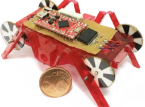
Fig. 1. The new foldable miniature quadruped robot, MinIAQ.
subsequent folding of a 2D sheet into a 3D functional struc-ture. Folding is an efficient and simple approach to planar fabrication of flexible 3D structures and can be employed as an alternative fabrication method to traditional machining or complex composite manufacturing processes. Yet, it is not extensively utilized in engineering fields due to its limiting factors such as planar design constraints, material selection limitations, and relatively complex folding and assembly tasks involved.
Kirigami, a subset of origami involving out-of-plane cuts [7], inspired developing a new planar fabrication process for microrobotic systems which is often referred to as printable, foldable, or print-and-fold robotics [8]. In this context, the term printing corresponds to engraving cut and fold patterns on sheets by utilizing a laser cutter or even by patterning 2D printable layers using 3D printers [9]. One of the advantages of printable or foldable robotics is that all transmission, flexure joints, and customizations can be embedded into a single 2D design, which not only is cheap and time-saving, but also eases the fabrication, assembly, and future design enhancements. Following the early works of [10], this technology was first developed by [8] and was later adapted by many researchers in designing their miniature grasping [11], [12], flying [13], and wormtype robots [14], [15] as well as some enhanced legged versions [16], [17], [18]. The method was further developed in [19] by implementing embedded circuitry through shape-memory composite planar designs to enable self-folding of the robot.
Despite the recent advancements in foldable robotics, there exists space for development in standardizing the hierarchical design process and folding elements to obtain high structural integrity and rigidity in a robotic platform. There aren’t many examples of complex foldable structures and most of the works rely on rather simple designs. We hereby aimed to design MinIAQ in a way to show the capability of this fabrication method for making complex robots and set a
2017 IEEE International Conference on Advanced Intelligent Mechatronics (AIM) Sheraton Arabella Park Hotel, Munich, Germany, July 3-7, 2017
paradigm for designing more complicated foldable structures with higher structural integrity and rigidity. MinIAQ is a quadruped foldable legged robot made from a single sheet of thin A4-sized PET film. The stiffening structures used in the robot and the overall unfolded structure design are not presented before, and thus this is one of the contributions of this manuscript. As another contribution of this paper, each leg is designed to be actuated individually by a small DC motor. This is different from previous miniature robots where one or two actuators are shared between legs to provide easier synchronous leg motion. Despite higher power consumption and greater challenge in phase synchronization control at such small scale, the idea of using one actuator per leg is to independently control the legs, achieve better maneuverability and in-place sharp turning, and have higher degree of freedom on controlling the overall robot’s motion. The main reason in designing a robot with individually actuated legs is not to claim that it is better or easier to control than miniature robots with coupled actuation but to enable gait modification during locomotion in a small scale for future studies. As an additional contribution, we designed custom absolute encoders for the small-yet-sensorless actu-ators to generate a single predefined signal that could be used to estimate both the speed and position of each leg and synchronize the legs accordingly. Even though the current version is a quadruped, the robot can be modified to have ‘n’ legs, if ‘n’ of these individually actuated legs are put together on a single body.
II. DESIGN OFMINIAQ A. Material Selection
In designing MinIAQ, we aimed to make an embedded single-piece crease pattern for ease of manufacturing. In order to select a proper material in terms of flexibility, rigid-ity, and joint durabilrigid-ity, 100, 250 and 500 micrometer thick PET sheets were selected as possible candidates. During the manufacturing process it was observed that the thinner sheets were easier to cut, fold and assemble. Despite the fact that rigidity increases with film thickness, it becomes harder to make folds and shape corners, especially by scaling down to smaller scale folds. In addition, the thicker sheets had lower joint performance since the joints made of thicker sheets would plastically deform and break much sooner than the thin sheets. Alternative structural materials can also be used to achieve enhanced mechanical properties such as increased stiffness or higher joint cycle life.
B. Rigid Linkages and Flexure Joints
In MinIAQ, rigid triangular beams and compliant flexure joints are used as the primitive components of the locomotion mechanism (Fig. 2). Rigid triangular beams are achieved by folding the sheets and locking into triangular prism shape. In this configuration, the beam’s rigidity is dependent on its length, width, thickness and Young’s modulus of material used [20]. Flexure joints are kinematic components that allow rotation in 1 DOF between two rigid links with the help of sheet flexibility. Even though flexure joints are very useful
components for miniature scale compliant mechanisms, they suffer from fatigue failure [21]. By optimizing the joint width, length and maximum deflection angle, life cycle of the flexure joints can be increased further by distributing the load more uniformly and reducing the stress at the joints. For the initial version of the MinIAQ, the joint designs are not yet optimized.
Fig. 2. Gait trajectory of the cam-driven four-bar mechanism with a detail view of the fundamental linkage and joint design in foldable robots. Inset shows hollow triangular beams with flexure joints.
C. Locomotion Mechanism Design
The first step towards a legged robot design and perhaps the foremost important stage is the design of its actuation mechanism. In foldable robotics context, it is quite challeng-ing to integrate a mechanism into the design which has good locomotion trajectory while having simple unfolded form. The flexure joints in foldable designs have limited degree of rotation, meaning that the links should not be bent very large with respect to each other so as to prevent shear at the joints [22]. This issue further aggregates the challenge in mechanism selection.
For MinIAQ’s legs, a simple four-bar cam-driven mecha-nism was designed and synthesized by altering the dimension of the leg, position of the joints and radius of the cam (input crank link) in order to obtain an acceptable gait path as shown by the trajectory in Fig. 2. The selected four-bar is not optimal performance-wise; it has relatively poor gait path and stride length. However, its simplicity was favored over complexity for the initial MinIAQ version due to ease of planar design and assembly. In future versions of MinIAQ, a more optimal transmission will be used.
D. Structural Integrity and Rigidity Improvement
A very important parameter influencing the payload capac-ity of a foldable robot is its structural integrcapac-ity. Due to having a thin flexible sheet as the base material, certain primitive folded structures were required to make the frame and link-ages hold their shapes. These primitive folded components set the basic design rules and act as subsets of any complex structure. As discussed, the legs were designed according to the hollow triangular linkage and perforated joint structures studied in the literature by [16], [20], [23], [24].
As an addition to the foldable robot design library in the literature, we propose to use T-shaped folds as fundamental elements in MinIAQ contributing to its high structural in-tegrity (shown in green in Fig. 3, 4, and 5). They act as out of plane extensions which not only stiffen the main robotic frame, but also can restrict transverse bending, buckling and belling of the robot. To lock the T-shaped folds in place, gluing or stitching can be a solution, but they are practically hard to implement for small parts and tiny extensions. The better approach is to utilize tab-and-slot fasteners to tightly
lock the parts into each other. On every T-fold, certain tabs are placed on one of the faces that locks into a slot. To firmly fix the position of a pair of T-folds and hold them in place with respect to each other, the tabs on each T-fold should be fastened into a single slot (see Fig.3(a)). Once the tabs are inserted through the slot, sides of the tabs are bent into U-shape to achieve proper locking in place as seen in Fig.3(a). The visual representation of locking mechanism for T-folds can be seen in Fig. 4 with red color. Note that a total of six (three on each side), equally spaced, double-sided T-fold fasteners are used on the main frame of MinIAQ. By using such fasteners, T-fold assemblies can be completed in minutes without needing any extra effort or hand skill.
(a)
(b) (c)
Fig. 3. (a) Unfolded crease pattern of two parallel T-shaped folds (green) with embedded U-shaped fasteners (red). The black dashed lines represent the folding lines. (b) Folded structure of T-folds with their U-shaped extension tabs fastened into a common slot in between. (c) Side view of the folded structure showing how the fasteners pass underneath the T-folds and lock into the slot from below.
In order to limit robot frame’s twisting under torsion and prevent unwanted dislocations, extension tabs (shown in yellow in Fig. 4) were made at the ends of the T-folds, which are tightly fitted through a slot. The friction between the extension tab and slot has enough locking force to prevent sliding of tabs due to torsion and any movement along the transverse direction. These tabs can be converted to U-shaped lockable tabs introduced in the next paragraph to achieve better locking but with slightly harder assembly.
To further improve the bending stiffness of the main frame, the T-folds located within the body are attached to the top cover of the main frame using two types of fasteners. The first type is the tight fit extension tabs and slots described in preceding paragraph that prevent buckling of T-folds by tight fitting the tabs on the upper side of the T-folds into a slot on the top cover (Fig. 4 - pink). The second type of fastener used to stiffen the main frame is U-shaped lockable tabs, which are practically tabs with foldable extensions on both sides that form a U-shape after inserting through a slot and folding the extensions inwards by 90◦ (Fig. 4 - blue). By fastening the U-shaped tabs on the T-folds through the slots placed on the top cover, we achieve fixing the T-folds rigidly in place that act as I-beam like structures. Therefore, by using ‘n’ number of T-folds within the structure and using tabs and U-shaped fasteners, the main frame technically becomes a rigid body supported by ‘n’ number of I-beams.
A challenging stage in the design was to find a folded structure to tightly hold the DC motors in place within the frame. Note that while using an external housing could be a solution, in foldable robotics the aim is to avoid using
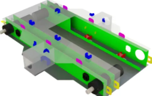
Fig. 4. A sectional view of MinIAQ’s main frame with tight fit motor housing using a pair of parallel T-folds and an IR sensor housing on the outer T-fold next to motors. •Green: T-shaped folds. •Red: Double-sided coupled locking tabs to fasten T-fold faces. •Yellow: T-fold end extension fasteners to restrict torsional twist and sliding dislocations (Holes are used to temporarily insert pins during assembly). •Pink: T-fold top extension fasteners to restrict torsional twist and sliding dislocations. •Blue: U-shaped lockable fasteners to form I-beam like structures from T-folds.
separate parts or materials as much as possible and restrict the work to a single uniform crease pattern. This was solved by using two sets of parallel T-folds on each side of the main frame and placing tight circular housings for the DC motors through each pair. T-folds increased the rigidity of the frame and also held the motors strongly in place. Thus, due to their out-of-plane structure, T-folds are very suitable for making housings such that any type of motor can be properly mounted onto the frame by a pair of parallel T-folds. Since MinIAQ is designed to have individual leg actuation, four T-folds were embedded into the design to enable four motor housings, one at each corner of the frame (Fig. 4 and 5).
(a) (b)
Fig. 5. (a) Unfolded structure of two T-folds with motor and sensor housings. The black dashed lines represent the folding lines. (b) Folded structure of T-folds with motor and sensor in place.
The rotational motion of the motors were transmitted to the legs with a cam shaft made of a thicker sheet film. Note that since the cam shaft, i.e. the crank link of the four-bar, has to rotate 360◦ in plane, it is very hard and complex, if not impossible, to achieve this with an origami flexure joint structure. Thus, the cam shafts were made and assembled from separate sheets and pins. These elements on the MinIAQ are the only mechanical structures on the robot that have to be manufactured separately. The cam shafts also serve as elements used in control and synchronization of the robot legs via IR sensors which are explained in detail in Section IV of the paper. Placing the sensors on the body is achieved by making a small housing next to the motors and inserting them within the outer T-folds. A small rectangular opening for the emitter and receiver on the outer side of the T-fold helps holding the sensor in place by preventing it from sliding inside the T-fold that can be seen in Fig. 5.
III. FABRICATION ANDASSEMBLY
This section explains the fabrication process of MinIAQ from scratch which takes less than two hours to cut and assemble. The process begins with laser cutting (using Uni-versal Laser Systems VLS 6.60) of the unfolded design from
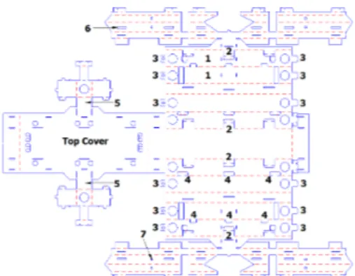
thin PET sheets which takes about 20 minutes. The design of MinIAQ was done in AutoCAD and its technical drawing cut file is shown in Fig. 6.
Fig. 6. The 2D unfolded technical drawing file used for laser cutting where dashed red lines represent the folding edges and continuous blue lines show full cuts. The labeled parts are explained in detail in the text.
The first step in assembling MinIAQ is folding the T-shaped folds. T-folds are labeled as 1 in Fig. 6. Once every four T-folds are folded, the IR sensors are placed inside their housing within the outer T-folds and wired to the PCB. Next, the T-folds are fastened by using double-sided tab and slot fasteners (Fig. 6-2) explained in Section II. After that, motors and sensors are placed into the housings that are located on the corners of the T-folds. Then, the extension tabs labeled as 3 in Fig. 6 are attached to the front and back of the main frame and are temporarily locked in place with small pins.
The top cover of the main frame is folded on top of the T-folds after passing the sensors and motor wires through the holes placed on the top cover. Once done, the tabs and U-locking fasteners existing on top of the T-folds (Fig. 6-4) are fastened to the top cover one by one.
Once the main body frame is enclosed, the supports carrying the load on the legs, shown in Fig. 6 labeled as 5 are assembled for increased rigidity. These supports consist of the same tab-and-slot and locking mechanisms explained in Section II. Prior to assembling the legs, wiring and placing electronic components should be done to avoid harming the flexure joints. Next, the legs are folded and their fasteners are locked to form rigid triangular beams. During the assembly process, positioning some of the interior extensions and locking U-shaped fasteners can be challenging. Introducing some slots such as the one labeled as 6 in Fig. 6 can help overcome this problem. With the help of these slots, one can access the fasteners easily with tweezers or a similar hand tool. Then, the cams are attached onto the DC motors’ shafts and connecting the legs and cams by inserting a pin through the pin holes (Fig. 6-7). The last step in the assembly process is to solder the battery, sensorsod and motors to the PCB.
The PCB used on MinIAQ has an Arduino Pro Micro con-troller that drives the four DC motors through two L293DD H-bridge motor drivers. A 3.7 Volts 150 mAh battery is placed inside the robot’s body. Using a step-up regulator its output is boosted to 5 Volts to power the main board, motor drivers and sensors. The completed MinIAQ is approximately 6 cm in width, maximum of 4.3 cm in height, and about 12 cm in length. In the absence of any components, the folded
structure weighs only 3.5 grams. The DC motors add a total of 5 grams and the PCB, electronic components, battery, and encoders add an extra 14.5 g to the platform making the weight of the current MinIAQ approximately 23 grams.
IV. OPERATION ANDCONTROL OFMINIAQ A. Control Problem and Ideal Gait Simulation
Due in part to the fact that efficiency of motors drop by scaling down as well as difficulties arising in control and weight optimization, researchers tend to use the least possible number of actuators in miniature robots. Despite its ease of control and lightweight design, this restricts having much degree of freedom on gait control and modification. MinIAQ is primarily designed to have independent leg actuation to enable full control on locomotion and gait adjustment for future gait studies in small scale. Inspired by quadrupedal-ism, terrestrial locomotion of four-legged animals, the ideal low-speed locomotion form for MinIAQ is to resemble that of trot gait. Trot is a form of movement where each diagonal pair of legs move together and the adjacent legs have 180◦ phase difference with respect to each other. Thus, the control problem boils down to leg synchronization, i.e. speed and phase control of the motors.
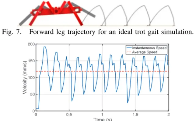
To better visualize the walking motion of the actual robot, a CAD model of the robot was developed in Solidworks with correct physical and material properties and a kinematic simulation was done using its Motion Analysis module. The results signified the importance of friction and contact area on the forward motion. A slight decrease in the friction coef-ficient resulted in noticeable slipping of the feet and inversely affected the forward motion. Fig. 7 illustrates the trajectory of the front legs for an ideal, maximized friction, trot motion and Fig. 8 presents the corresponding result of the simulation where the forward velocity of the robot in millimeters per second is shown for a motor speed of 3 Hz. The results imply that MinIAQ can ideally perform a trot gait at an average speed of 12 cm/sec if run at 3 Hz which corresponds to approximately 1.0 Bodylengths/sec. In actual walking trials, the robot is often run at 3 Hz motor drive frequency and due to the non-ideal conditions such as less friction and contact between the ground and the feet, the feet often slip and slide on the ground. The resulting forward speed was measured to be approximately 0.65 Bodylengths/sec (7.5 cm/s) from more than ten experiments at 3 Hz drive frequency. Independent actuation of each leg enables better maneuverability such as performing in position zero-radius turning. The robot turns in-place about 20◦/s at 3 Hz motor speed. Increasing the friction between the feet and the surface may help the robot to operate closer to the ideal case and perform faster turns. Moreover, the front leg lifts to a level higher than the main frame (Fig. 7) resulting with relatively large roll and pitch values during walking. The robot’s frame was observed to be very shaky in actual tests, having ±21◦ in roll angle and 0◦ to 11◦ in pitch angle at 3 Hz. An optimized leg actuation mechanism with a stable trajectory can result in a more balanced walk and turn.
Fig. 7. Forward leg trajectory for an ideal trot gait simulation. 0 0.5 1 1.5 2 Time (s) 0 50 100 150 200 Velocity (mm/s) Instantaneous Speed Average Speed
Fig. 8. Variation of forward velocity of the simulated robot with respect to time for a rotational motor frequency of 3 Hz.
B. Custom Encoder Design and Control Input Signal Considering the choice of having four actuators on board, one of the smallest and lightest available DC motors was selected as the actuator. However, these motors lack exten-sion shafts for encoder attachments. For determination and control of both speed and position of each leg, small analog IR sensors were selected as MinIAQ’s only sensing device and were embedded into the design next to the motors. An absolute encoder with a single black band was designed and integrated with the actuation mechanism cam-shaft (crank linkage) as shown in Fig 9(a). The output signal of this cam resembles a single peak per cycle signal where for a walking motion with nominal frequency of about 2.5 to 3 Hz, it does not provide more than a few discrete inputs in each cycle to the controller. Thus, during walking trials, it was observed that the speed of the control loop was insufficient to compensate for the highly varying loads on the motors. In an effort to increase the number of sampled data inputs and rate of control, a 3D encoder cam shown in Fig. 9(b) was designed. Due to the sensitivity of IR sensors to distance, the amplitude of the peak for the gray band becomes noticeably smaller than those of the black bands. By this means, the position of the legs over the entire cycle can be estimated based on the smaller peak reference. Fig. 9(c) represents the analog output signal of the 3D cams with 28 detected discrete input data points that are used for motors’ speed control and phase synchronization. Note that to obtain a 180◦phase difference between the diagonal leg pairs, only the position of the crank pin holes on each encoder pair are placed with 180◦ offset. Thus, by synchronizing the signals of all four cams to have zero phase, we ensure having 180◦ phase difference on the legs resembling the ideal trot gait locomotion.
(a) (b)
0 100 200 300 400 500 600 700 800 900 1000 1100 Sample # from the IR Sensor
0 0.5 1 1.5 2 2.5
IR Sensor Voltage Output (V)
(c)
Fig. 9. (a) Single black band cam shaft encoder. (b) 3D cam shaft encoder. (c) A 3D encoder analog output signal with 28 sample points detected per cycle for the controller input.
C. Performance of PD Control for Trot Gait Synchronization Since the speed of DC motors are linearly dependent on input voltage, a PD controller was designed for frequency and phase control using the feedback signals from the 3D encoders. An integral term was not added to the linear con-troller since the system’s type number is zero corresponding to no steady state error. The frequency of each motor is estimated using two consecutive data points of the same colors shown on the signal in Fig. 9(c) which correspond to 60◦rotation. Since encoders are custom made and are prone to uncertainty and errors, using data points of different colors to estimate the frequency may result in higher measurement errors as the degree traveled in between them are unknown. The phase lead or lag of each motor is also estimated by measuring its time difference with respect to the same data point of a reference motor. These calculated error signals are the inputs of the frequency and phase PD controller. The resulting trot gait synchronization is shown by snapshots from a video in Fig. 10 for one motor period. Fig. 11 and 12 also represent the time responses of frequency and phase control, respectively. In this case motor 1 is an arbitrarily selected reference motor where its speed is only controlled and motor 2 corresponds to any of the other motors that does simultaneous speed and phase control with respect to the signal from motor 1. The data was collected through serial communication for the front motors’ speeds and phases.
As can be seen from the time responses, high uncertainty and errors are unavoidable due to measurement errors and signal noise. In fact, increasing the sampling rate of the system and sampled data points may even inversely affect the controller’s performance in presence of any kind of measurement uncertainty. Regardless of controller’s perfor-mance, increasing the sampling rate makes the controller more sensitive to rate of error change and can result in destabilization of the system, especially due to existence of derivative term in PD. This behavior was clearly seen where adding more discrete data inputs beyond some point did not improve the settling and controller’s performance.
V. CONCLUSION ANDFUTUREWORK
In this manuscript we are introducing a new foldable miniature quadruped robot, MinIAQ, made out of a single PET sheet. In order to stiffen the body where needed, “T-shaped” folds are introduced. The robot’s legs are actuated individually in order to provide future ability to change gaits. The actuators are quite small, but they do not have encoders. Therefore, we have designed our custom encoders to control the gait of the robot. The resulting robot is untethered and weighs approximately 23 grams. Even though it is the first version and none of the mechanical structures and gait patterns are optimized, MinIAQ can still walk with a speed of 0.65 Bodylengths/sec.
There are several improvements and case studies that can be done following the work initiated herein. A thorough modeling and study on the fatigue performance of foldable flexure joints is to be done to characterize their behavior in
Fig. 10. Snapshots of the PD controlled trot gait synchronization of MinIAQ over one period at 3 Hz running frequency. The moment of touch-down of one leg is in sync with the lift-off of the other from the ground and vice versa.
0 Time (s) 1 1.5 2 2.5 3 3.5 Frequency (Hz) Motor1 Freq. Motor2 Freq. Desired Freq. 1 2 3 4 5 6 7
Fig. 11. Front motors’ speed control.
Time (s) 20 40 60 80 100 120 140 160
Absolute Phase Error (deg
°)
0 1 2 3 4 5 6 7
Fig. 12. Phase control of motor 2 with respect to motor 1 with estimated absolute angular error between leg positions.
a better way and maximize their life span. A comparison be-tween different cases such as perforated and non-perforated joints, increased width and thickness, and effects of bonding a layer of soft material onto the joints, like kapton, will be performed. To eliminate the current leg slip issues, it is aimed to optimize the transmission by studying alternative leg and locomotion mechanism designs. Last but not least, mathematical modeling of the system, plant identification, and implementing new control schemes are to be sought.
ACKNOWLEDGMENTS
The authors would like to thank every group member of Bilkent Microrobotics Laboratory for their assistance throughout this project. This work is funded by the Scientific and Technological Research Council of Turkey (T ¨UB˙ITAK) grant no. 115C107.
REFERENCES
[1] O. Ozcan, A. T. Baisch, D. Ithier, and R. J. Wood, “Powertrain selection for a biologically-inspired miniature quadruped robot,” in 2014 IEEE International Conference on Robotics and Automation (ICRA). IEEE, 2014, pp. 2398–2405.
[2] R. S. Pierre and S. Bergbreiter, “Gait exploration of sub-2 g robots using magnetic actuation,” IEEE Robotics and Automation Letters, vol. 2, no. 1, pp. 34–40, Jan 2017.
[3] J. M. Bustillo, R. T. Howe, and R. S. Muller, “Surface micromachin-ing for microelectromechanical systems,” Proceedmicromachin-ings of the IEEE, vol. 86, no. 8, pp. 1552–1574, 1998.
[4] J. Whitney, P. Sreetharan, K. Ma, and R. Wood, “Pop-up book mems,” Journal of Micromechanics and Microengineering, vol. 21, no. 11, p. 115021, 2011.
[5] A. M. Hoover, E. Steltz, and R. S. Fearing, “Roach: An autonomous 2.4 g crawling hexapod robot,” in Intelligent Robots and Systems, 2008. IROS 2008. IEEE/RSJ International Conference on. IEEE, 2008, pp. 26–33.
[6] R. Wood, S. Avadhanula, R. Sahai, E. Steltz, and R. Fearing, “Micro-robot design using fiber reinforced composites,” Journal of Mechanical Design, vol. 130, no. 5, p. 052304, 2008.
[7] J. Rossiter and S. Sareh, “Kirigami design and fabrication for biomimetic robotics,” in SPIE Smart Structures and Materials+ Non-destructive Evaluation and Health Monitoring. International Society for Optics and Photonics, 2014, pp. 90 550G–90 550G.
[8] C. D. Onal, R. J. Wood, and D. Rus, “Towards printable robotics: Origami-inspired planar fabrication of three-dimensional mecha-nisms,” in Robotics and Automation (ICRA), 2011 IEEE International Conference on. IEEE, 2011, pp. 4608–4613.
[9] R. MacCurdy, R. Katzschmann, Y. Kim, and D. Rus, “Printable hydraulics: a method for fabricating robots by 3d co-printing solids and liquids,” in Robotics and Automation (ICRA), 2016 IEEE International Conference on. IEEE, 2016, pp. 3878–3885.
[10] A. M. Hoover and R. S. Fearing, “Fast scale prototyping for folded millirobots,” in Robotics and Automation, 2008. ICRA 2008. IEEE International Conference on. Ieee, 2008, pp. 886–892.
[11] M. Salerno, K. Zhang, A. Menciassi, and J. S. Dai, “A novel 4-dof origami grasper with an sma-actuation system for minimally invasive surgery,” IEEE Transactions on Robotics, 2016.
[12] E. Vander Hoff, D. Jeong, and K. Lee, “Origamibot-i: A thread-actuated origami robot for manipulation and locomotion,” in 2014 IEEE/RSJ International Conference on Intelligent Robots and Systems. IEEE, 2014, pp. 1421–1426.
[13] Y. Mulgaonkar, B. Araki, J.-s. Koh, L. Guerrero-Bonilla, D. M. Aukes, A. Makineni, M. T. Tolley, D. Rus, R. J. Wood, and V. Kumar, “The flying monkey: A mesoscale robot that can run, fly, and grasp,” in 2016 IEEE International Conference on Robotics and Automation (ICRA). IEEE, 2016, pp. 4672–4679.
[14] C. D. Onal, R. J. Wood, and D. Rus, “An origami-inspired approach to worm robots,” IEEE/ASME Transactions on Mechatronics, vol. 18, no. 2, pp. 430–438, 2013.
[15] K. Zhang, C. Qiu, and J. S. Dai, “Helical kirigami-enabled centimeter-scale worm robot with shape-memory-alloy linear actuators,” Journal of Mechanisms and Robotics, vol. 7, no. 2, p. 021014, 2015. [16] C. D. Onal, M. T. Tolley, R. J. Wood, and D. Rus, “Origami-inspired
printed robots,” IEEE/ASME Transactions on Mechatronics, vol. 20, no. 5, pp. 2214–2221, 2015.
[17] M. Agheli, S. G. Faal, F. Chen, H. Gong, and C. D. Onal, “Design and fabrication of a foldable hexapod robot towards experimental swarm applications,” in 2014 IEEE International Conference on Robotics and Automation (ICRA). IEEE, 2014, pp. 2971–2976.
[18] S. T. Kalat, S. G. Faal, U. Celik, and C. D. Onal, “Tribot: A minimally-actuated accessible holonomic hexapedal locomotion platform,” in Intelligent Robots and Systems (IROS), 2015 IEEE/RSJ International Conference on. IEEE, 2015, pp. 6292–6297.
[19] S. Felton, M. Tolley, E. Demaine, D. Rus, and R. Wood, “A method for building self-folding machines,” Science, vol. 345, no. 6197, pp. 644–646, 2014.
[20] S. G. Faal, F. Chen, W. Tao, M. Agheli, S. Tasdighikalat, and C. D. Onal, “Hierarchical kinematic design of foldable hexapedal locomotion platforms,” Journal of Mechanisms and Robotics, vol. 8, no. 1, p. 011005, 2016.
[21] L. L. Howell, Compliant mechanisms. John Wiley & Sons, 2001. [22] L. U. Odhner and A. M. Dollar, “The smooth curvature flexure model:
An accurate, low-dimensional approach for robot analysis,” Proc. Robot.: Sci. Syst. VI, pp. 137–144, 2010.
[23] C. Sung and D. Rus, “Foldable joints for foldable robots,” Journal of Mechanisms and Robotics, vol. 7, no. 2, p. 021012, 2015.
[24] A. M. Mehta and D. Rus, “An end-to-end system for designing mechanical structures for print-and-fold robots,” in 2014 IEEE In-ternational Conference on Robotics and Automation (ICRA). IEEE, 2014, pp. 1460–1465.