EFFECTS OF SOME TRANSITION METAL SALTS ON THE SYNTHESIS OF MESOPOROUS SILICA
A THESIS
SUBMITTED TO THE DEPARTMENT OF CHEMISTRY AND THE INSTITUTE OF ENGINEERING AND SCIENCES
OF BILKENT UNIVERSITY
IN PARTIAL FULFILLMENT OF THE REQUIREMENTS FOR THE DEGREE OF
MASTER OF SCIENCE
By
AHMET FAİK DEMİRÖRS July 2005
I certify that I have read this thesis and in my opinion it is fully adequate, in scope and in quality, as a thesis of the degree of Master of Science
___________________________________ Assoc. Prof. Dr. Ömer DAĞ
I certify that I have read this thesis and in my opinion it is fully adequate, in scope and in quality, as a thesis of the degree of Master of Science
___________________________________ Prof. Dr. Şefik SÜZER
I certify that I have read this thesis and in my opinion it is fully adequate, in scope and in quality, as a thesis of the degree of Master of Science
___________________________________ Assoc. Prof. Dr. Margarita KANTCHEVA
I certify that I have read this thesis and in my opinion it is fully adequate, in scope and in quality, as a thesis of the degree of Master of Science
___________________________________ Asst. Prof. Ayşen YILMAZ
I certify that I have read this thesis and in my opinion it is fully adequate, in scope and in quality, as a thesis of the degree of Master of Science
___________________________________ Asst. Prof. Dönüş TUNCEL
Approved for the Institute of Engineering and Sciences
____________________________________ Prof. Dr. Mehmet BARAY
ABSTRACT
EFFECTS OF SOME TRANSITION METAL SALTS ON THE SYNTHESIS OF MESOPOROUS SILICA
AHMET FAİK DEMİRÖRS M.S. in Chemistry
Supervisor: Assoc. Prof. Dr. Ömer DAĞ July 2005
True Liquid Crystal (TLC) templating approach has been extensively used to produce mesostructured silica films and monoliths. It is known that nonionic surfactants (CnEOm) are suitable templates for this purpose. In this work, we have introduced various transition metal salts into mesostructured silica materials through TLC approach. The work has two aims; one is to introduce large quantities of metal ions into the silica channels and second is to study the effect of the metal cation and the counter anion to the structure of the mesophase. Current understanding about the solubility of non-ionic surfactants in aqueous media is that, the solubility decreases upon dehydration. Salting-out ions (according to the Hofmeister series) that cause dehydration will decrease the solubility of surfactants. Due to the solubility change the concentration and the type of salt will affect the structure of the LC template and as a result the mesostructured silica. The total charge (ionic strength) of the system has also a principal role on the structure of the mesophase. High ionic strength will decrease the solubility and influence the assembly of the surfactant molecules into LC mesophases. Although an alkaline metal perchlorate anion makes the surfactant more soluble than nitrate anion in a water:surfactant system, the transition metal perchlorates are harder to dissolve compared to nitrate salts in a salt:surfactant system. This fact is due to the coordination of the nitrate ion to the metal cation. Upon coordination the ionic strength decreases and this
increases the solubility of transition metal nitrates. However the perchloriate ion does not coordinate to a transition metal cation.
In this thesis, the structural changes in the transition metal salt (TMS):CnEOm:silica systems were investigated using diffraction (XRD), microscopy (POM) and spectroscopy (FTIR and micro-Raman) techniques. The [Co(H2O)6](NO3)2 salt silica systems are hexagonal up to 1.2 salt/C12EO10 mole ratio and over this concentration the mesophase is cubic. Usage of a surfactant with longer alkyl chain
(C18EO10) increases this phase change over 2.0 mole ratio. However, the
[Co(H2O)6](ClO4)2 salt:silica systems have cubic structures at very low salt/C12EO10 mole ratios (above 0.2 mole ratio), whereas they are hexagonal when no perchlorate salt is added.
It has been demonstrated that the LC mesophases of the TMS:Pluronic(triblock copolymer surfactant family) systems exist with a very rich structural chemistry. The TMS:Pluronic systems have lamella, hexagonal, various types of cubic and a tetragonal mesophases. The TMS:P65 and TMS:P123 systems are ordered and well structured. The hexagonal mesophase in the [Zn(H2O)6](NO3)2:P65 systems and the tetragonal and cubic LC mesophases in the [Zn(H2O)6](NO3)2:P123 systems were identified. The LC mesophases of TMS:Pluronics can be used as templating agents for the synthesis of stable mesostructured silica. The lamella mesostructured silica obtained using [Zn(H2O)6](NO3)2:P123 LC mesophase transforms to 2D hexagonal structure upon calcinations (goes from layered structure to long channel hexagonal tubes).
Keywords: Lyotropic liquid crystals, mesophases, transition metal aqua complexes, non-ionic surfactants, Pluronics, mesoporous materials, Hofmeister effect.
ÖZET
BAZI GEÇİŞ METALİ TUZLARININ MEZO-YAPILI SİLİKA SENTEZİ ÜZERİNE ETKİLERİ
AHMET FAİK DEMİRÖRS Kimya Bölümü Yüksek Lisans Tezi Tez Yöneticisi: Doç. Dr. Ömer DAĞ
Temmuz 2005
Sıvı kristal kalıplama (SKK) yöntemi mezoyapılı silika film ve monolit sentezinde sıkça kullanılmaktadır. İyonik olmayan yüzey-aktiflerin(CnEOm) bu amaçla kullanılmaya müsait kalıplar olduğu bilinmektedir. Bu çalışmamızda SKK yöntemi ile çeşitli geçiş metali tuzlarının silika materyal yapıya katılımını sağladık. Bu çalışmanın iki amacı vardır, birisi mezoyapılı silika içerisine büyük miktarlarda metal iyonu hapsetmek, ikincisi ise geçiş metal katyon ve anyonlarının mezoyapıya etkisini araştırmaktır. İyonik olmayan yüzey-aktiflerin sulu çözeltilerdeki çözünürlüğünün yüzey-aktifin sudan arındırılmasıyla azaldığı düşünülmektedir. Hofmeister serisine göre tuzlanmayı artırıcı (salting-out) olarak sınıflandırılan anyonlar, yüzey-aktiflerinin kurumasına (dehydration) neden olur ve yüzeyaktifin çözünürlüğünü azaltırlar. Çözünürlükteki değişiklikler nedeniyle geçiş metali tuzlarının derişimi ve çeşidi SK kalıbın yapısını ve sonuç olarak da mezoyapılı-silikanın yapısında değişikliklere neden olmaktadır. Sistemdeki tuzlardan kaynaklanan toplam elektrik yükünün de (ionik direncin) mezofazın yapısında önemli rolü vardır. Yüksek iyonik direnç, aktifin çözünürlüğünü azaltır ve yüzey-aktiflerin kendilerini SK mezofaza organize etmelerini etkiler. Su:yüzey-aktif sistemlerinde, alkali metal perklorat anyonunun yüzey-aktiflerin çözünürlüğünü nitratlara göre artırıyor olmasına rağmen, geçiş metal perklorat tuzlarının nitrat tuzlarına göre daha zor çözülür. Bu durum nitrat iyonunun metal katyonuna koordinasyonun bir sonucudur.
Koordinasyon sonucunda sistemin toplam elektrik yükü azalır ve böylece geçiş metali tuzunun çözünürlüğü artar. Halbuki perklorat iyonu metal katyonuna koordine olma özelliği yoktur.
Bu tezde geçiş metali tuzları (GMT):CnEOm:silika sistemindeki yapısal değişiklikler kırınım (XRD), mikroskopi (POM) ve spektroskopi (FT-IR ve mikro-Raman) teknikleri ile tetkik edilmiştir. [Co(H2O)6](NO3)2:silika sistemleri 1,2 tuz/C12EO10 mol oranına kadar hegzagonal yapıda iken, bu derişimin üzerinde mezoyapı kübiktir. Daha uzun alkil zincirli yüzey-aktiflerin kullanımı bu faz değişimini 2,0 mol oranının üzerine taşır. Perklorat tuzu eklenmemiş sistemler hegzagonal yapıda olmalarına rağmen. [Co(H2O)6](ClO4)2:silika sistemi çok düşük tuz/C12EO10 mol oranlarında (0,2 mol oranı ve üzerinde) dahi kubik yapıdadır.
GMT:Pluronik sıvı kristal mezofazlarının çok zengin yapısal kimyaya sahip olduğu gösterilmiştir. GMT:Pluronik sistemler lamella, hegzagonal, değişik kübik ve tetragonal yapılara sahiptir. GMT:P65 ve GMT:P123 sistemleri düzenli ve oldukça güzel yapılıdır. [Zn(H2O)6](NO3)2:P65 sistemlerinde hegzagonal, [Zn(H2O)6](NO3)2:P123 sistemlerinde tetragonal ve kübik SK mezofazlar tayin edilmiştir. GMT:Pluronik SK mezofazları, mezoyapılı silika sentezinde kalıp olarak kullanıbilinir. Tuz:Pluronik kullanılarak elde edilen mezoyapılı silika filimler ve/veya monolitler genelde lamela yapıdadır. [Zn(H2O)6](NO3)2:P123 SK mezofazı kalıp olarak kullnıldığında lamela mezoyapılı olmasına rağmen, yüksek sıcaklıklarda yakılmasıyla 2D hegzagonal yapıya dönüşür (katmanlı yapıdan, uzun tünelli hegzagonal tüblere geçer).
Anahtar kelimeler: Liyotropik sıvı kristaller, mezofazlar, geçiş metal sulu kompleksleri, iyonik olamayan yüzey-aktifler, Pluronikler,
ACKNOWLEDGEMENT
I would like to express my deep gratitude to Assoc. Prof. Dr. Ömer DAĞ for his encouragement and supervision throughout my studies.
I am very thankful to Nesibe CINDIR, Olga SAMARSKAYA, Yaşar AKDOĞAN, Oğuzhan ÇELEBİ, Anıl AĞIRAL, Korcan DEMİROK, Mehtap KÜYÜKOĞLU, and my home mates Mesut ŞAHİN, Süleyman TEK , Hüseyin ACAN, Aşkın KOCABAŞ and all present and former members of Bilkent University Chemistry Department for their kind helps and supports during all my study.
TABLE OF CONTENTS
1.INTRODUCTION………..1
1.1. MESOPOROUS INORGANIC MATERIALS ……….1
1.2. TRUE LIQUID CRYSTALLINE TEMPLATING…………..…………10
1.3. METAL CONTAINING LIQUID CRYSTALS………..………12
1.4. HOFMEISTER SERIES AND SALT EFFECTS ON THE SELF ASSEMBLY………..17
2.EXPERIMENTAL………27
2.1.MATERIALS………...27
2.2.SYNTHESIS………27
2.2.1. Synthesis of Liquid Crystal Phase of Inorganic Salts………...27
2.2.2. Synthesis of Mesoporous Silica by Liquid Crystal Templating………..28
2.2.3. Calcination of the LC Templated Mesoporous Silica………..29
2.3.INSTRUMENTATION………...…30
2.3.1. Polarized Optical Microscopy………..……30
2.3.2. X-Ray Diffraction………30
2.3.3. FT-IR Spectroscopy……….30
2.3.4. Micro-Raman Spectroscopy ………31
3.RESULTS AND DISCUSSIONS……….32
CHAPTER-1………....…32 3.1.1. Effects of Transition Metal Salts on Synthesis of Mesostructured Silica.32
3.1.2. Polarized Optical Microscopy (POM) of Mesostructured Silica ……....32 3.1.3. XRD Analysis………...…...………36
3.1.3.1 Mesostructured Silica Monoliths using [Co(H2O)6](NO3)2:C12EO10 LC Systems………...….39 3.1.3.2 The Mesostructured Silica Films of Co+2-meso-SiO2….………...45 3.1.3.3 Monoliths of [Co(H2O)6](ClO4)2:C12EO10:HClO4:TMOS systems …….……….46 3.1.4 FT-IR and Micro-RAMAN SPECTRAL ANALYSIS………..…...51
CHAPTER-2………..………54
3.2.1. LC Mesophases of Pluronics……….….54
3.2.2. XRD and POM Results of LC mesophases of
H2O:[Zn(H2O)6](NO3)2:Pluronic(L64, P65, P123) Systems……...55 3.2.3.FT-IR and micro-Raman Spectroscopy Results for the LC Mesophases
of TMS:Pluronic Systems and Water Vaporization Process of the
TMS:Pluronic Systems………...66 3.2.4 [Zn(H2O)6](NO3)2:Pluronics:Silica and [Zn(H2O)6](ClO4)2:P123:Silica
Systems………...73
4.CONCLUSION……….………81 5.REFERENCES………..83
LIST OF TABLES
1.1 Nomenclature of Porous Inorganic Materials according to their pore sizes……..1 1.2 Mesophases of silicate molecular sieves and the synthesis parameters…………7
1.3 General properties of SBA and MCM type mesoporous silicas………..…10
3.1.1 Physicochemical Properties of Mesoporous Silica (SBA) Prepared Using
Nonionic Alkyl Poly(ethylene oxide) Surfactants………...…….…….…....43 3.2.1 d-spacing and (hkl) values obtained from different mole ratios of the
[Zn(H2O)6](NO3)2:P65 LC mesophase using the diffraction patterns in Figure 3.2.2………....58 3.2.2. The d-spacing and (hkl) values evaluated from the XRD two patterns of
[Zn(H2O)6](NO3)2:P123 systems with a)4 and b) 6 mole ratio,( XRD patterns in Figure 3.2.8)………...63
LIST OF FIGURES
1.1 Illustrations of mesoporous M41S materials: a) MCM-41, b) MCM-48, and c) MCM-50………...……….3 1.2 Formation of microporous and mesoporous molecular sieves by using short and
long alkyl chained quaternary ammonium salts………4 1.3 Schematic representation of the various types of inorganic-surfactant head group
interactions: electrostatic: a) S+I-, b) S-I+, c) S+X-I+, and d) S-M+I-; hydrogen bonding: e) S°I° and f) N°I°; and covalent bonding: g) S-I………..6 1.4 Representative phase transition, from solid to liquid crystal and then to liquid
phase………...…13 1.5 Various types of surfactants………..…………..14 1.6 Frequently observed lyotropic liquid crystalline phases, formed when a solvent
and amphiphilic macromolecules are mixed………..……15
1.7 Schematic phase diagram for C16TMABr in water……….……….16
1.8 UV-vis absorption spectra of [Co(H2O)6]Cl2:H2O:CnEOm during the water
evaporation. The inset shows the expanded, 400-600 nm spectral range with the neutral [Co(H2O)4Cl2] complex and [Co(H2O)6]2+complex ion species……….20 1.9 XRD patterns of [Cd(H2O)4](NO3)2/[Cd(H2O)4](ClO4)2:C12EO10 mixed-salt
systems. The nitrate-to-perchlorate mole ratios are (A) 0.0:2.0, (B) 1.5:0.5, and (C) 1.8:0.2 (the metal ion-to-surfactant moleratio is 2.0 in all samples)…...….22
1.10 The POM images of the [Cd(H2O)4](NO3)2/[Cd(H2O)4](ClO4)2:C12EO10 mixed-salt systems. The nitrate-to-perchlorate mole ratios are (A) 1.8:0.2, (B) 1.5:0.5, and (C) 0.0:2.0 (the metal ion-to-surfactant mole ratio is 2.0 in all samples)…23
1.11 XRD patterns of MCM-41 displayed relative to the amounts of inorganic salts added to the synthesis mixtures: (A) NaCl, (B) KCl, (C) Sodium acetate, (D) Na4EDTA. Numbers given to XRD patterns are salt-to-HTACl molar ratio. The “water treated” data were collected after heating the calcined samples in boiling water for 12 h……….…….24
3.1.1. POM image for the A) hexagonal and B) cubic mesophases of
[Co(H2O)6](NO3 )2:C12EO10:HNO3:TMOSsalt system………34 3.1.2. Typical XRD patterns of mesostructured materials a) 2D hexagonal,
b) 3D hexagonal, c) cubic , d) lamellar...38 3.1.3. The [Co(H2O)6](NO3)2 :C12EO10:HNO3:TMOS samples with varying salt
concentrations. A) Salt-free sample (silica without any salt addition), salt/surfactant mole ratio B) 0.4 assigned as hexagonal , C) 1.2 assigned as hexagonal , D)1.6 assigned as cubic, E)2.0 assigned as cubic, F) 3.0 assigned as cubic, X axis is the 2θ angle………..…………...40 3.1.4 Suggested mechanism for the HI-Im3m transition. Undulations form in the
hexagonal phase rods, with the rods being “pinched” at regular intervals, and this continues until the narrowest points along the rods are pinched off, and discrete micelles form………..……41 3.1.5 XRD patterns of samples with 2.0 moles [Co(H2O)6](NO3)2 salt /surfactant
texture under POM). Inset is XRD of [Co(H2O)6](NO3)2 2.0 salt /surfactant ratio with C12EO10 surfactant sample and the plot of the d-spacing versus (hkl) relation……….44 3.1.6 The POM images of [Co(H2O)6](NO3)2:CnEOm: HNO3:TMOS system with
salt/surfactant mole ratio of 2.0, A) with C18EO10 surfactant and B) with
C12EO10 surfactant………45
3.1.7 XRD patterns of dip-coated [Co(H2O)6](NO3)2:C12EO10:Silica samples with various salt/surfactant mole ratios……….……..46 3.1.8 The XRD spectra of the [Co(H2O)6](ClO4)2:C12EO10:HClO4:TMOS system
with 0.2 mole ratio by time, a) in15 minutes, b) after 1 day, c) after 2
day………47 3.1.9 The XRD patterns of 1 day aged samples of
[Co(H2O)6](ClO4)2:C12EO10:HClO4:TMOS system with mole ratios a) 0.2, b) 0.4, c)0.6, d)0.8, e)1.0………..47 3.1.10 The XRD patterns of salt free-samples of C12EO10:HClO4:TMOS system
with 0.060 g HClO4 by time a) immediately after preparation, b)10
minutes, c) 20 minutes………..49 3.1.11 XRD patterns of salt free-samples of C12EO10:HClO4:TMOS system with
0.1 g HClO4 by time a) immediately, b) 20 minutes, c) 1 day after
preparation………...….50 3.1.12 XRD patterns of salt free-samples of C12EO10:HClO4:TMOS system with
0.03 g HClO4 by time a) immediately, b) 10 minutes, c) 2 hours after preparation. The hexagonal (100) and (200) diffraction lines are shown for (a)………..51
3.1.13 The FT-IR spectra of [Co(H2O)6](NO3)2:C12EO10:Silica system with 1.2 salt/surfactant ratio and NaNO3. a) NaNO3, b)
[Co(H2O)6](NO3)2:C12EO10:Silica system immediately after preparation, c) 3 hours after preparation d) 1 day after preparation...……….52 3.1.14 Micro-Raman Spectra of a) [Co(H2O)6](NO3)2 and
[Co(H2O)6](NO3)2:C12EO10:Silica system with salt/surfactant ratios b)0.6, c)1.4, d) 1.6……….………..53
3.2.1 The XRD patterns of [Zn(H2O)6](NO3)2:L64 with salt-to-L64 mole ratios of a) 2.25, b) 2.75, c) 3.25, d) 3.75 and e) 4.0……….………..56 3.2.2 The XRD patterns of [Zn(H2O)6](NO3)2:P65 with salt surfactant mole ratios
of (a) 3.0, (b) 4.0 (c) 5.0, (d) 6.0………..…….57 3.2.3 POM image of the [Zn(H2O)6](NO3)2:P65 with salt/surfactant mole ratio
6.0………....57 3.2.4 The XRD patterns of the LC [Zn(H2O)6](NO3)2:P65 system with a 4.0 mole ratio at 3 different orientation (sample is 1 day old)………...58 3.2.5 The the plot of d-spacing versus (hkl) relationship of the 3D hexagonal
structure. The slope gives the parameter a which is 79.7Å………...…..….59 3.2.6 The XRD patterns of [Zn(H2O)6](NO3)2:P123 LC mesophases with a) 2, b)
3.2.7 The XRD patterns of the [Zn(H2O)6](NO3)2:P123 systems after complete water evaporation with [Zn(H2O)6](NO3)2/P123 mole ratio of (a) 9.0 (b) 7.0, (c) 6.0 and (d) 4.0………..61 3.2.8 The XRD patterns of the LC [Zn(H2O)6](NO3)2:P123 systems (a) with a 4.0
salt to P123 mole ratio (b) is the same pattern as of (a) that is multiplied by 10 in the region of 2.0o-5.5o and (c) with a 6.0 salt to P123 mole ratio...… 62 3.2.9 XRD pattern of 4.0 [Zn(H2O)6](NO3)2:P123 after one week of water
evaporation, measured in different orientation (top) rotated to right (middle) as packed (bottom) rotated left with respect to beam-detector axis……..…63 3.2.10 Schematic representation of the [Zn(H2O)6](NO3)2:P123 mesophases (left is
the tetragonal and right is the cubic mesophases), small dots are representing the ions in the media, hairy parts represent PEO and the dark red parts represents the PPO units of P123)………...…….65 3.2.11 FTIR spectral changes with the evaporation of water from the
[Zn(H2O)6](NO3)2:P123 system with 5.0 mole ratio (I) immediately after sample preparation,(II) after equilibrium at RT, (IV) heated at 100oC,(III) cooled to RT and (V)Subtraction of (IV) from (I)………67 3.2.12 FTIR spectra of the [Zn(H2O)6](NO3)2:L64 and L64 (top),
[Zn(H2O)6](NO3)2:P65 and P65 (middle) and [Zn(H2O)6](NO3)2:P123 and P123 (bottom) with the same salt/pluronic mole ratios (Zn(II)/PEO ratio was 6.15 in all samples)………..…….68 3.2.13 The micro-Raman spectra of [Zn(H2O)6](NO3)2:P123 with 6.15 salt to
surfactant ratio before (a) and after (b) equilibrium at RT and heated
3.2.14 The XRD patterns of H2O:[Zn(H2O)6](NO3)2:P123 with a 7.0 mole ratio, (a) before water evaporation (b) 1 hour after water evaporation at RT, (c) heated sample at around 100oC (d) kept at RT for 1 hour after (e) x10 of (d)………..…71 3.2.15 XRD pattern of 4.0 mole ratio H2O:[Zn(H2O)6](NO3)2:P65 (a) immediately
after phase appears upon water evaporation, (b) after 1 hour of water evaporation (c) heated (b) a few minutes for complete water evaporation on a hot plate and cooled to RT and (d) 1 hour cooling of (c)………...……72 3.2.16 The XRD patterns of the [Zn(H2O)6](NO3)2:P65:Silica samples with a)0.0 1
hour after sample preparation and b)0.0 immediately after sample preparation, c)1.0, d) 3.0, e) 5.0, f) 7.0, g) 9.0 salt-to-P65 mole
ratio………...74 3.2.17 The XRD pattern of the [Zn(H2O)6](NO3)2:P123:Silica system with 1.0
salt-to-P123 mole ratio……….………75
3.2.18 The XRD pattern of the [Zn(H2O)6](NO3)2:P123:Silica samples with 1.0 salt-to-P123 mole ratio. The pattern is taken after 5 days from the sample preparation………...….76 3.2.19 The plot of d-spacing of lines in Figure 3.2.17 versus 1/h. The slope of the
plot gives the parameter a as 96.68 Ǻ. ……….76 3.2.20 The XRD patterns of [Zn(H2O)6](NO3)2:P123:Silica samples with
3.2.21 The XRD patern of [Zn(H2O)6](ClO4)2:P123:Silica system with 1 salt/P123 mole ratio………..78 3.2.22 The plot of d-spacing versus the (hkl) relation for the cubic mesophase of
[Zn(H2O)6](ClO4)2:P123:Silica system with 1 salt/P123 mole
ratio………...78 3.2.23 The XRD patterns of [Zn(H2O)6](NO3)2:P123:Silica with salt-to-P123 ratio
1 a) before calcination, b) calcined at 300˚C, c) calcined at 500˚C for 5 hours………..79
1. INTRODUCTION
1.1 Mesoporous Inorganic Materials
According to IUPAC definition Inorganic solids with pore diameter sizes in the range of 20 to 500 Ǻare called mesoporous materials. Examples of mesoporous materials such as M41S family (Family of well defined mesostructures synthesized by the Mobil Research group), aerogels (dry gels), and pillared layered structures are listed in Table 1.1 [1]
Table 1.1 Nomenclature of Porous Inorganic Materials according to their pore sizes. Pore Size Definition Example Actual size range
Macroporous > 500 Ǻ Glasses > 500 Ǻ Mesoporous 20-500 Ǻ Aerogels > 100 Ǻ Pillared layered clays 10 Ǻ, 100 Ǻ
M41S 16-100 Ǻ
Microporous < 20 Ǻ Zeolites, zeotypes < 14.2 Ǻ
Activated carbon 6 Ǻ
Mesoporous materials are used extensively as heterogeneous catalysts and adsorption media along with microporous materials. The function of these materials, in their
Large internal surfaces and cavities are the important keywords for catalytic activity and adsorptive capacity. A major subclass of the microporous materials is molecular sieves. The most known example for molecular sieves is zeolites. Zeolites are aluminosilicates which have micropores (< 14.2 Ǻ in pore size) that are regular arrays of uniformly-sized channels. Zeolites are crystalline solids and they exhibit an extremely narrow pore size distribution. Due to these properties zeolites are very important in size selective catalysis [2], ion exchange [3], desiccation and sorption [3] reactions. Zeolites are also used as nanoreactors for host-guest chemistry [4].
Typical mesoporous materials known are amorphous or paracrystalline solids, such as silicas[5] or transitional aluminas[6] or modified layered materials such as pillared clays and silicates[7-11]. These materials generally have irregularly spaced pores, broadly distributed in size [8]. Due to this fact there has been a significant effort to synthesize materials within the mesoporous range with well defined properties and a regular structure. Before the pioneering work of Mobil researchers [12], the investigations of mesoporous materials were not that significant because they were not actually in mesoporous range. Cacoxenite, a natural ferroaluminophosphate with 14 Ǻ channels nearly in mesoporous size range was characterized [13] and A1P04-8,[14] ,VPI-5,[15]: and cloverite [16] which have pore diameters within the 8-13 Ǻ range were synthesized. Common property for many of these materials is their lack of thermal or hydrothermal stability. In 1990`s the researchers at Mobil-Oil-Corporation used long chained alkyl-ammonium ions [CH3(CH2)nN(CH3)3+ ] in an attempt to increase the pore size of zeolites [12]. Note that he amphiphilic molecules with a hydrocarbon chain length of n less than eight are normally too small to self assemble (and for the supramolecular templating) in an aqueous solution and would be expected to behave as molecular templating agents (as in zeolite synthesis). Here the deriving force for the self-assembly is the tendency of organic tails to stay together in an aqua solution.
Navrotsky et al [17] have found that MCM-41, which is the mesoporous silica with 2D hexagonal structure and zeolites are thermodynamically only slightly less stable than the stable phase of silica, α-quartz. This means that the synthesis of mesoporous silica
with desired porosity and size is thermodynamically available if the appropriate kinetic pathway is used.
For the first time the mobil researchers [12] achieved to synthesize mesoporous molecular sieves with regular, well-defined channels in a variety of pore sizes, ranging from 15 to 120 Ǻ (designated as M41S). Especially one of the members of the family, MCM-41, is extensively investigated. It has a hexagonal arrangement of uniform mesopores with well defined, tunable pore sizes. These materials with larger pore sizes have high surface areas above 700 m2/g and hydrocarbon sorption capacities of 0.7 cc/g and greater. The Mobil researchers proposed the liquid crystal templating mechanism (LCT) for the M41S family.The liquid crystal structures formed by the surfactant molecules serve as organic templates for assembly of the mesostructured silica. The MCM-41, 2D hexagonal mesoporous phase is the first reported example of mesoporous silica materials [12]. The surfactant templating has also been applied to synthesize materials in cubic, MCM-48 and lamella, MCM-50 forms additional to hexagonal, MCM-41 silica materials, see Figure 1.1
Figure 1.1 Illustrations of mesoporous M41S materials: a) MCM-41, b) MCM-48, and
c) MCM-50 [18].
In general, the M41S family of mesoporous molecular sieves was synthesized by combining appropriate amounts of a silica source (e.g. tetraethylorthosilicate
(TEOS), fumed silica, sodium silicate), an alkyltrimethylammonium
aged at temperatures usually over 100° C for 24 to 144 hours, resulted in a solid precipitate. The organic-inorganic mesostructured product was then filtered, and washed with water, and air-dried. The product was calcined at about 500 °C under a flowing gas. At this temperature the surfactant burns off and the mesoporous inorganic material is left. Note that the templates used in these approachs are ionic alkyltrimethylammonium halide surfactants with a long alkyl chain. It is known that the small alkyl chain quaternary directing agents were used for zeolite synthesis, see Figure 1.2. The benefit of the ionic alkyltrimethylammonium halide surfactant with a long alkyl chain is that they assemble into micelle structures whereas the small alkyl chain quaternary agents were templating the zeolites (alone) in the molecular level, see Figure 1.2. The key feature of the MCM family is the ability to modify the structure and the ability to control the pore size (20-100 Ǻ) by changing the synthesis conditions (e.g. surfactant chain length, addition of auxiliary organics)
Figure 1.2. Formation of microporous and mesoporous molecular sieves by using short
The Mobil researchers proposed a liquid crystal templating (LCT) mechanism for the M41S family, particularly MCM-41, because of the similarity between the liquid crystalline surfactant assemblies and M41S family. They proposed two mechanistic pathways for the 2D hexagonal structured MCM-41 [12, 20]. (Scheme 1.1):
1) The hexagonal lyotropic liquid crystalline (LC) phase is formed first and then the inorganic precursor species deposit on the micellar rods of the LC phase.
2) The inorganics mediated, in a way, the ordering of the surfactants into the hexagonal arrangement. The surfactants were not ordered but the silica species organize the structure formation.
Scheme 1.1. Two possible pathways for LCT [20].
In both cases the positively charged ammonium head groups of the surfactants interact with the inorganic components that are negatively charged at the high pH values used and pack into a solid framework. The silica species surrounds the hexagonally arranged surfactant micellar rods. It is now a common consensus that pathway 1 is unlikely, because the surfactant concentrations used are much below the critical micelle concentration (CMC) necessary for hexagonal LC formation [21]. The second mechanistic pathway of LCT was assumed as a cooperative self-assembly of the ionic ammonium surfactant and the silicate precursor species below the CMC.
Later a generalized liquid crystalline templating mechanism [22] was proposed based on electrostatic interaction of the inorganic precursor (I) and the surfactant head group (S). In this model, the synthesis of MCM type mesoporous materials was based on the aggregation of cationic surfactant (S+) and anionic inorganic species (I-). However various types of pathways such as (S-I+), (S+X-I+) X= Cl-, Br- or (S-M+I-) M= Na+, K+ were used to synthesize mesoporous materials [22], see Figure 1.3.
Figure 1.3. Schematic representation of the various types of inorganic-surfactant head
group interactions: electrostatic: a) S+I-, b) S-I+, c) S+X-I+, and d) S-M+I-; hydrogen bonding: e) S°I° and f) N°I°; and covalent bonding: g) S-I. [18]
In acidic media, pH~2 the silicate species become cationic (I+) but still cationic surfactant (S+) can be used to synthesize mesoporous materials by S+X-I+ system [22, 23].
Here counter ion X- behaves as a shielding agent between the S+ and I+. The materials synthesized by this approach are known as “acid prepared mesostructures” (APM) or SBA [18,22].
To predict the phase of a given LC system as a first approximation of the mesophase of the silica, two parameters were considered to be important for the two synthesis routes of the synthesis of silicate mesoporous molecular sieves. For the basic route (S+I-) used to synthesize the M41S family, made up of three well defined mesostructures: MCM-41, MCM-48, and MCM-50, the key synthesis parameter that determined the mesophase was surfactant/silicon molar ratio. The surfactant /silicon molar ratio as a prediction parameter was first suggested by Vartuli et al [24], see Table 1.2. At ratios below 1 the hexagonal phase MCM-41 is observed and between 1 and 1.5 cubic phase, MCM-48 is observed and at higher ratios lamellar phase, MCM-50 is observed.
Name Space group&Mesophase Parameter ________________________________________________________________________ MCM-41[1, 24] hexagonal, p6m [surfactant]/[Si]<1 MCM-48[1, 24] cubic, Ia3¯d [surfactant]/[Si] =1-1.5 MCM-50[1, 25] lamellar, p2 [surfactant]/[Si] =1.2-2 SBA-1[26, 27] cubic, Pm3¯n g=1/3[a]
SBA-2[28] 3D hexagonal, P63/mmc g<1/3[a] SBA-3[26] 2D hexagonal, p6m g=1/2[a] Lamellar g=1 [a] g= V/a0l.
Table 1.2. Mesophases of silicate molecular sieves and the synthesis parameters [18].
In the acidic route (S+X-I+), used to synthesize the cubic SBA-1, 3D hexagonal SBA-2 and 2D hexagonal SBA-3, the key synthetic parameter to predict the mesophase
the surfactant, effective head group area, ao, and surfactant chain length, l. The packing
parameter g was defined by Huo et al [28] as g= V/ ao.l. When the packing parameter g is
1/3 the cubic SBA-1 is observed and over this value the structure tends to be 3D hexagonal SBA-2. At higher g levels, when g is equal to 1/2, the 2D hexagonal structured SBA-3 is observed and when g is equal to 1 the observed mesophase becomes lamellar, Table 1.2. For the acidic preparation route, there is a tendency from cubic structure to hexagonal and lastly to lamellar structure as the g parameter increases.
Due to the different precipitation conditions and charge balance requirements, the acid-derived materials (SBAs) have thicker pore walls and a framework charge different from the base-derived mesoporous materials. For instance, the overall framework charge of SBA-3 (acidic condition)was slightly positive whereas the framework of MCM-41(basic condition) was negative. One important thing that was observed for the SBA materials was that the space group of SBA-2 is P63/mmc. Its structure is hexagonal close-packed (hcp) array of spheres (known as 3D hexagonal); whereas this structure is rarely found in the traditional LC systems.
Stucky and his group [29] introduced a family of highly ordered mesoporous silica structures by using commercially available nonionic alkyl poly(ethylene oxide) oligomeric surfactants (CnH2n+1(OCH2CH2)mOH) and Pluronics [triblock poly(ethylene oxide)-poly(propylene oxide)-poly(ethylene oxide) (PEO-PPO-PEO) copolymers] in acidic media.They achieved to synthesize mesostructured materials in 20-300 Å range. Stucky`s group found that the nonionic oligomeric surfactants frequently form cubic or 3D hexagonal mesoporous silica structures, whereas the nonionic triblock copolymers tend to form hexagonal (p6mm) mesoporous silica structures. They also found out that the surfactants with short EO segments tend to form lamellar mesostructured silica at room temperature.The EO/PO ratio of the copolymers is an important parameter and lowering this ratio of the triblock copolymer advances the formation of lamellar mesostructured silica, while increasing this ratio promotes cubic mesostructured silica formation [29]. The calcined ordered mesoporous silicas produced by this path are thermally stable in
boiling water for 48 h. Note also that the MCMs lack this property. This higher stability is most probably due to the thicker walls of these materials (31-64 Å), compared to the MCM-41 (10-15 Å).
In this process, that takes place in acidic media the non-ionic surfactant molecules interact with the proton (H+) and this promotes the hydrogen bonding interaction between the inorganic precursors and the surfactants by the shielding of the X- anions. Briefly, the assembly of the structure takes place by a (S0 H+)(X-I+) pathway. SBA-15, one of the best of this SBA family, is prepared by either Pluronic P123 ( EO20PPO30EO20) or C16EO10 and has a 2D hexagonal structure (p6mm). SBA-15 has very promising properties compared to MCM-41, it has pores sizes up to 300 Ǻ (120 Ǻ for MCM-41) and has thicker walls than MCM-41, that are up to 64 Ǻ and pore volumes up to 2.2 cm3/g, and BET surface areas up to 910 m2/g [18]. Table 1.3 gives shows the types of mesoporous materials and gives information about their properties (mesophase and d -spacing) and from which surfactant they are produced.
Table 1.3. General properties of SBA and MCM type mesoporous silicas [18].
________________________________________________________________________ Name of the Material Surfactant(s) Mesophase d *(Ǻ)
________________________________________________________________________ MCM-41 [CH3(CH2)nN(CH3)3+ ]Br - 2D hexagonal 15-120 MCM-48 [CH3(CH2)nN(CH3)3+ ]Br - cubic 80.33-92 MCM-50 [CH3(CH2)nN(CH3)3+ ]Br- lamellar 36.2 SBA-1 [CH3(CH2)nN(CH3)3+ ]Br - cubic SBA-2 [CH3(CH2)nN(CH3)3+ ]Br - 3D hexagonal 40.8-57.3 SBA-3 [CH3(CH2)nN(CH3)3+ ]Br- 2D hexagonal SBA-11 C16EO10 Pm3hm cubic 56.6 SBA-12 C18EO10 3D hexagonal (P63/mmc) 49-77 SBA-14 C12EO4 3D cubic 45.3 SBA-15 P123,C16EO10 2D hexagonal(p6mm)103-108,64.1 SBA-16 F127 EO106PO70EO106 cubic (Im3hm) 124 ________________________________________________________________________ *d is the d(100) value of the material.
1.2. True Liquid Crystalline Templating (TLCT)
The lyotropic liquid crystalline phase of a polyethylene oxide surfactant was first used by Attard et al. for the synthesis of monolithic mesoporous silicates [30] which is basicly a one piece bulk material without cracks. Tetramethylorthosilicate (TMOS) was directly added into the previously existing LC mesophase to produce a hexagonal mesostructured silica; Attard et al. also showed that the cubic and lamellar phases could be synthesized by using various tail chain length. This method was considered as a TLCT path, which also showed the possibility of the pathway 1, proposed LCT mechanism for MCM-41 (Scheme 1.1). In this method the existence of the LC mesophase is more important than the interaction of the silica precursors and the surfactant to cooperate and form the mesophase.
Göltner and co-workers [31] showed that nonionic amphiphilic diblock copolymers with a polyethylene oxide head group and a polystyrene tail group could also be used as templates to create crack-free mesoporous silica monoliths. Amphiphilic diblock copolymers (ABCs) are known to form micelles when mixed with water or other suitable solvents [32]. Additionally they form lyotropic liquid crystalline phases at higher polymer concentrations. Göltner and Antonietti et al [31] also demonstrated that ABC templates show a number of advantages. Firstly, polymer chemistry is very rich and the polymeric amphiphile can be synthesized or modified to the desired product. Thus, a rich family of surfactants can be available for mesoporous material preparation. Secondly, a larger size of the templating is achieved, which determines the pore diameter (as an important property) and the wall thickness (for the stability) of the mesoporous materials.
Another alternative approach for the synthesis of mesoporous molecular sieves was proposed by Pinnavaia et al [33]. They have used primary amine nonionic surfactants for the synthesis. The primary amine nonionic surfactants at low concentration [33] yielded similar materials to M41S. Note that the oligo(ethylene oxide) surfactants [34] forms less regular mesostructures than M41S (this was proven by the presence of a single X-ray diffraction peak at low angles) but they still exhibite high specific surface area and narrow pore size distributions. In the category of nonionic surfactants both primary amines and oligo(ethylene oxide), CnEOm surfactants were used to mediate the formation of mesoporous materials[33,34]. However natural alkyl amines are costly and toxic therefore they are not suitable for large-scale production of mesoporous materials, whereas the CnEOm type surfactants are biodegradable and offer synthetic flexibility. Additionally with the CnEOm type surfactants, it is possible to prepare mesoporous transition metal oxides that are not accessible by electrostatic templating method. The metal alkoxides that readily hydrolyze to the corresponding metal oxide can also be templated by CnEOm type nonionic surfactants [34].
1.3. Metal Containing Liquid Crystalline Mesophases
Solids, liquids and gasses are the three most known forms of matter. In the solid state, the forces between the molecules are strong and the molecules have firm arrangement, therefore each molecule occupies a certain place which means that they have a positional order. The matter can be either amorphous or crystalline in solid state. In crystalline case, molecules are also oriented in a specific direction; it means that they have orientational order additional to the positional order. In this situation highly ordered arrangement causes additive attractive forces. In liquid state, the intermolecular forces are less than the solid state and molecules have neither positional order nor orientational order. The molecules in the gas phase have even less intermolecular forces so they also do not have positional and orientational order.
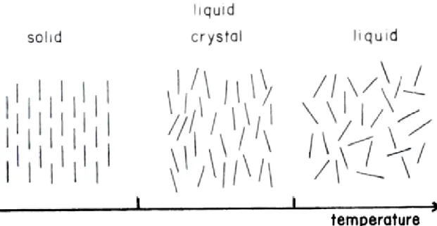
The liquid crystalline (LC) state is the state of the matter which has the properties of both liquid and solid states. In LC phase, the molecules or aggregates have some orientational order but no positional order in all directions [35]. The orientational order of the molecules is represented in Figure 1.4 [35]. In the LC phases, the molecules have tendency to stay in some direction rather than others. This phase can be distinguished from isotropic liquid phase by its opaque appearance and solid phase by its flow properties. There are two main liquid crystalline phases in terms of order. One is Nematic, which has orientational order and no positional order. Other is Smectic, which has orientational order and positional order only in one dimension, is formed in layered structures.
Figure 1.4. Representative phase transition, from solid to liquid crystal and then to liquid
phase.
The LC phases are also divided into two categories according to their formation, thermotropic and lyotropic LCs. The thermotropic LCs include calamitic (rod like), discodic (disc like) and polymeric LCs. They are obtained by heating of solid crystals of certain materials. Particularly, as the temperature increases, the thermotropic mesophases change phases from crystal to smectic then to nematic and finally to the liquid phase [35-36].
Lyotropic liquid crystals (LLC) are multi component systems formed in mixtures of amphiphilic molecules and a polar solvent. The LLC formation depends on the concentration of the former amphiphiles in an appropriate solvent [35-38]. Amphiphilic molecules are consisted of a hydrophilic polar head attached to a hydrophobic hydrocarbon tail containing one or two alkyl chains. They have dual character and have both hydrophilic (affinity for water) and hydrophobic (affinity for oil) parts.
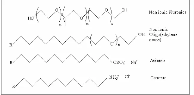
There are various kinds of surfactants, which can be classified as anionic, cationic, amphoteric and non-ionic based on their head groups. Figure 1.5 shows some examples
of surfactants. In this work two types of non-ionic surfactants are used, one is oligo(ethylene oxide) type with hydrophobic long alkyl chains and hydrophilic polyoxyethylene (-CH2CH2O-, PEO) head group and the other is the triblock
poly(ethylene oxide)-poly(propylene oxide)-poly(ethylene oxide) (PEO-PPO-PEO) copolymers.
Figure 1.5. Various types of surfactants.
When surfactants are added into water their hydrophobic parts tend to stay away from water. This tendency to avoid water causes the surfactant molecules at very low concentrations to stay on the air/water interface with hydrophobic part orients towards air to decrease the interaction with water. As the concentration of the surfactant is increased the dissolved surfactant molecules assemble and form micelles. The required concentration for the micelle formation is called the Critical Micelle Concentration (CMC) [39]. Further increase in surfactant concentration far beyond the CMC leads to the ordered mesostructure formation. In the micelle structure the hydrophobic hydrocarbon chains orient themselves inside the aggregate and the polar head groups adjust themselves toward the aqueous phase.
The formation of micelles from the surfactant molecules and finally the formation of the various mesostructures are shown in Figure 1.6.
Figure 1.6. Frequently observed lyotropic liquid crystalline phases, formed when a
solvent and amphiphilic macromolecules are mixed [39].
The micelle structures are self-assembly of the surfactant molecules which originates from the weak intermolecular forces such as van der Waals, dipole-dipole interactions and hydrogen bonds (not due to strong covalent or ionic bonds) so the structure of the micelle may change in size or shape in response to changes in concentration, salt content, temperature, pH. Therefore, it is possible to obtain mesophases with different structures by changing the surfactant concentration and/or temperature. Figure 1.7 [40] shows the phase diagram of the C16H33(CH3)3NBr (C16TMABr ) which shows structural changes with surfactant concentration and temperature. Note that these kinds of phase diagrams can also be obtained by changing the pH and salt concentration.
Figure 1.7. Schematic phase diagram for C16TMABr in water [39].
Dag et al. introduced a new lyotropic liquid crystalline (LLC) system of oligo(ethylene oxide) surfactants with transition metal salts (TMS), [M(H2O)n]Xm (without water as a solvent) [40]. The LLC phase was formed by mixing appropriate amounts of the TMS and the oligo(ethylene oxide) surfactants. In this binary system the transition metal aqua complexes induces the oligo(ethylene oxide) surfactants to self-assemble into a LC phase. In this LC mesophase formation the hydrogen bonds formed between the metal aqua complex hydrogens and the ethoxy oxygens has an important role. This LC phase is stable for months up to 3.0 salt/surfactant mole ratios.
Dag et al. also found out that the structure of the [M(H2O)x]Y2:CnEOm binary
mesophases usually display 2D hexagonal structure in nitrate systems and cubic in perchlorate systems. However the chloride salt binary systems do not have the mesophase. Indeed the chloride TMS are almost insoluble in the oligo(ethylene oxide)
1.4 Hofmeister Series and Salt Effects on the Self assembly
It is well known that oligo(ethylene oxide) molecules form LC mesophases depending on the concentration of water in the media. The LC phase occurs because the oil-like tail group of the amphiphile tends to minimize the interaction with water and forms micelles whereas the hydrophilic part likes to stay outside the micelle in the water regions. Usually these systems included metal salts as the third or fourth component [42-48] of the mesophase. Recently in our group the liquid crystalline (LC) phase behavior of different transition metal aqua complexes, MYx.nH2O (M= Co+2 , Ni+2, Cd+2, Zn+2, Fe+2)(Y= NO3-, Cl-, SO4-2 , CH3COO-), with oligo(ethylene oxide) type non-ionic surfactants (salt:CnEOm) were investigated [49]. The system shows LC phase with or without addition of water into the system [49].
Synthesis of mesoporous solid materials using LC systems is known and it has been well established that the polymerization of the silica takes place in the hydrophilic domains of the LC mesophase [30]. In this assembly process, the LC phase acts as a structure-directing agent (template). In this thesis we also used LC templating method to produce mesoporous silica with high internal surface area and cavities that are essential for catalysis and high adsorptive capacity. Usually an electrolyte is added to improve the properties of the materials [50]. Addition of electrolytes is also known to affect the structure of the LC phase [51-56]. Therefore electrolytes will also play an important role in the structure of silica materials.
The effects of electrolytes on the solubility of the surfactant are separated into two categories. One of which is the effect of anions on solubility of the surfactant molecules. This effect is known for almost more than hundred years as the Hofmeister effect. Hofmeister divided the anions into two categories according to their effects on the solubility of proteins (the same tendency is observed for the solubility of the surfactants) [57]. Anions such as NO3- and ClO4- that increase the solubility of the surfactants are known as “salting-in” and the others such as SO 2- an Cl- that decrease the solubility of
the surfactants are known as “salting-out” anions [58]. Hofmeister stated that the salting out effect of the anions decreases as the following:
SO42- > HPO42- > CrO4- > CO32- > Cl- > Br-> NO3-> I-> ClO4->SCN-
Ions on the left of Cl-, which represents a borderline, reduce the solubility of proteins and surfactants. They are generally called salting-out ions, water structure-makers or cosmotropic ions. The opposite holds for ions on the right of Cl-, known as salting-in, or water-structure-breakers, or chaotropic anions. These anions increases the solubility of surfactants in water.
The well known properties of the salting-out anions are that they have low polarizability and high charge. They hold their hydration water strongly in the solution and they do not interact with other ions directly but with the coordinated water molecules. These properties for the salting-in anions are vise versa: high polarizability, low charge and easy lose of the hydration water.
As mentioned above the effects of the electrolytes are emphasized with their different properties. One is the hydrophilicity change of the surfactant and the other is the structure formation of water. The salting-out electrolytes will decrease the hydrophilicity of the surfactants whereas salting-in anions will increase the hydrophilicity of the surtactant in the media. Similar properties of anions are discussed by biologist from another point of view. They categorize the electrolytes as, some makes water a better solvent (structure breakers) and some makes it a worse solvent (structure makers) for EO chains [59]. The association of water molecules which is enhanced by structure makers and the distruption of the association of water by structure breakers is shown below:
nH2O (H2O)n
in the surfactant, whereas the SO42- and PO43- anions are less polarizable and they are more electronegative therefore they are structure makers and salt-out the surfactant [52].
In addition to this anion effect on solubility there is also cation effect (or coordination effect) which comes due to the coordination of anions to the transition metal cation. Obviously, this effect is not observed with alkali or earth alkali metal cations. However, anions, which coordinates to the metal cation are also important because not all anions have the same ability to coordinate.Upon coordination, the net charge ( or ionic strength) in the solution decreases that increases the solubility of the salts in the nonionic surfactants(or LC media). This is observed for the salt:CnEOm systems of transition metal nitrate and perchlorate salts.
Although ClO4- anionis more salting-in according to the Hofmeister series NO3- salts of the same metal cation is more soluble in the salt:surfactant systems. This observation is not a result of Hofmeister effect but due to some other effect which decreases the ion density (ionic strength) of the media. This effect is due to the coordination reaction given below [41] :
[M(H2O)4]2+ + 2NO3- [M(H2O)3(ONO2)]+ + NO3- + H2O
The fact is that ClO4- anion cannot coordinate to the metal cation; therefore the ion density in the perchlorate system is higher; higher the ion density, lower the solubility of the perchlorate salts.
Another interesting example is the coordination of Cl- ion to the Co+2cation in the [Co(H2O)6]Cl2:CnEOm system .Usually metal chloride salts are insoluble in the binary
salt: surfactant systems except cobalt (II) chloride ([Co(H2O)6]Cl2 ). The solubility of the cobalt (II) chloride salt is enhanced by the following equilibrium reaction [41]:
n [Co(H2O)6]2+ + (2n)Cl- (Rxn. 1.)
400 500 600 700 800 0,0 0,4 0,8 1,2 1,6
time
Absorbance
Wavelength (nm)
450 500 550 600 650 0,00 0,03 0,06 0,09 [CoCl4] 2-[Co(HO) Cl ] [Co(H2O)6] 2+ Absorbance Wavelength (nm) 2 4 2Figure 1.8. UV-vis absorption spectra of [Co(H2O)6]Cl2:H2O:CnEOm during the water
evaporation. The inset shows the expanded, 400-600 nm spectral range with the neutral [Co(H2O)4Cl2] complex and [Co(H2O)6]2+complex ion species[41].
The liquid (with excess water) and LC samples with enough water content are purple in color and upon the evaporation of water color changes to a sharp blue. Dag et al monitored the evaporation of water by UV-vis/near-IR spectrophotometry in the visible region [41]. The bands at around 690 nm, which originates from the [CoCl4]2- ion, increase in intensity with water evaporation [60], see Figure 1.8.
[Co(H2O)4Cl2] complex is also observed during the water evaporation process. The peaks at 454 and 530 nm are characteristic for the [Co(H2O)4Cl2] complex [41,60]. These observations prove that there is an equilibrium between [Co(H2O)4Cl2] neutral and [Co(H2O)6]2+,[CoCl4]2- ion complexes as stated in the above equilibrium reaction.
Note that at the right hand side of the equilibrium reaction (Rxn. 1) there is water and this says that water is the key determining component of the equilibrium which is parallel with the observations.
Recently Dag et al.[61] introduced the effects of TMSs type and the concentration on the LC mesophase by working on LLC mesophase of TMS:oligo(ethylene oxide) nonionic surfactants (CnH2n+1(CH2CH2O)mOH, denoted as CnEOm), systems. They found
that the nitrate salts are more soluble in the surfactant media than the perchlorate salts. This is due to the coordination of nitrate ions to the transition metal cation. The coordination of nitrate ion to the transition metal cation decreases the ion density of the media and increases the solubility of the salt in the surfactant.The structure of the [M(H2O)x]Y2:CnEOm (Y is Cl-, NO3-, and ClO4-) mesophase is usually 2D hexagonal in nitrate systems(some nitrate salts also display cubic structure at high salt concentrations), cubic in perchlorate systems. The structure of the LC changes from hexagonal to cubic phase as the ion density of the TMS:CnEOm system increases. At the same mole ratios the nitrate salts display hexagonal where as the perchlorate salts display cubic. This observation is due to lower ion density of the nitrate sample due to the coordination [61]. Dag et al carried out an experiment to observe the ion density effect on the LC
mesophase. In their experiment they held the metal ion /C12EO10 molar ratio constant (at 2.0 molar ratio) in a [Cd(H2O)4](NO3)2/[Cd(H2O)4](ClO4)2:C12EO10 mixed-salt systems. The change of the structure from 2D hexagonal (perchlorate free sample) to 3D
hexagonal (1.5:0.5 of NO3-/ClO4- molar ratio) and to cubic (0.2:1.8 of NO3-/ClO4 molar ratio) is proven by XRD and POM techniques, see Figure 1.9 for the XRD patterns and Figure 1.10 for the POM images below [41].
Figure 1.9. XRD patterns of [Cd(H2O)4](NO3)2/[Cd(H2O)4](ClO4)2:C12EO10 mixed-salt systems. The nitrate-to-perchlorate mole ratios are (A) 0.0:2.0, (B) 1.5:0.5, and (C) 1.8:0.2 (the metal ion-to-surfactant moleratio is 2.0 in all samples) [41].
Figure 1.10. The POM images of the [Cd(H2O)4](NO3)2/[Cd(H2O)4](ClO4)2:C12EO10 mixed-salt systems. The nitrate-to-perchlorate mole ratios are (A) 1.8:0.2, (B) 1.5:0.5, and (C) 0.0:2.0 (the metal ion-to-surfactant mole ratio is 2.0 in all samples)[41].
1.5. Salts (Electrolytes) in Synthesis of Inorganic Mesoporous Materials and Their Effects on the Mesoporous Products
Electrolytes are almost always present in the synthesis of mesoporous materials. Salts are known to have significant effects on the formation mechanism of mesoporous materials. Electrolytes generally increase the stability of the materials by developing the interface properties [50]. Note that if LCT is used for the mesoporous material synthesis the effects of the salt on the LC will also affect the structure of the mesoporous materials.
It is known that MCM-41 has high thermal and hydrothermal stability against air and oxygen containing water vapor. However, it has a low hydrothermal stability in boiling water and aqueous solutions [62-64].Chen et al.[62] reported that pure-silica MCM-41 could be heated up to 1123 K and do not lose its stability. Additionally Kim et al.[63] showed that the powder X-ray diffraction (XRD) pattern and BET surface area of the MCM-41 were not significantly affected by heating up to 1170 K in air and in O2 containing water vapor with pressures up to 2.3 kPa (0.023 atm). More recently, Kim and
flow at 770 K. In contrast to such stability of MCM-41 in air, O2, and steam at high temperatures, it was found that MCM-41 collapses during heating in boiling water and in aqueous solutions [64]. The structural loss involved silicate hydrolysis in water and aqueous solutions.
Figure 1.11. XRD patterns of MCM-41 displayed relative to the amounts of inorganic
salts added to the synthesis mixtures: (A) NaCl, (B) KCl, (C) Sodium acetate, (D) Na4EDTA. Numbers given to XRD patterns are salt-to-HTACl molar ratio. The “water treated” data were collected after heating the calcined samples in boiling water for 12 h [64].
Ryoo and Jun [65] introduced that low hydrothermal stability in hot water and aqueous solutions which was a critical problem for many applications of the mesoporous molecular sieve MCM-41 could be overcame and improved remarkably by using various salts like sodium chloride, potassium chloride, sodium acetate, and ethylenediaminetetraacetic acid tetrasodium salt (Na4EDTA). High-quality MCM-41
samples investigated under XRD gave very insignificant losses in boiling water. Improvement by addition of salt in the synthesis media can easily be seen in Figure 1.11. The XRD patterns of MCM-41 with addition of different salts with different amounts are shown in Figure 1.11: Graphs include additional salts as follows (A) NaCl, (B) KCl, (C)
Sodium acetate, and (D) Na4EDTA. The numbers on the XRD patterns are the
salt/HTACl molar ratios. It is seen for all the experiments that the addition of salt stabilizes the structure against boiling water. However after an upper limit the salt loses its benefit.
In addition, Stucky and Zhao[66] reported that the addition of inorganic salts, especially highly charged salts such as K2SO4, can increase the interaction of silicate species with hydrophilic head groups of nonionic block copolymers and the strong interaction of head groups with the silicate species can result in long-range ordered domain of silica-surfactant mesostructures finally the long-range order favors the formation of mesoporous single crystals. Briefly, Stucky and Zhao found that extra salt addition stimulates the formation of single crystal materials instead of amorphous materials.
In their experiments Stucky and Zhao [66] used non ionic triblock copolymer surfactants (F108) and K2SO4 in acidic media and they achieved to synthesize cubic (Im3m) mesoporous single crystals. However with the same reactants without adding salt, they only obtained amorphous gel. A decrease of concentration of K2SO4 from 0.5 to 0.25 mol/L resulted in no precipitates from solution. They found that Na2SO4 also gives single crystals when it is used instead of K2SO4. This means that the anion has more effect on the structure and highly charged anions favor the formation of single crystals. However, using the anion Cl- instead of SO42- gave rise to mixed morphologies.
In this thesis we have studied the effect of salt, type and amount on the synthesis of mesostructrued silica, produced by LCT. The resulting materials were characterized by
XRD, POM, FT-IR and micro-Raman spectroscopy. As the salt concentration or more generally as the ion density increases the structure of the mesostructured silica also tends to shift from hexagonal to cubic mesophases. These observations will be extensively discussed throughout the results and discussion parts.
2. EXPERIMENTAL
2.1 Materials
All chemicals and solvents were reagent grade and used as received without any further treatment.
Several surfactants were used throughout this work; homogeneous polyoxyethylene 10 lauryl ether C12H25(OCH2CH2)10OH, (designated as C12EO10) and Brij 76 (C18EO10) are commercially available from Aldrich, Germany. The triblock copolymers having a poly(ethylene oxide)-poly(propylene oxide)-poly(ethylene oxide) (EO-PO-EO) so called Pluronics, L64 (PEO13PPO30PEO13, Mav = 2900), P65 (PEO20PPO30PEO20, Mav = 3500), and P123 (PEO20PPO70PEO20, Mav =5800) were generously donated by BASF Corp. and used without further treatment.
Cobalt(II) nitrate hexahydrate([Co(H2O)6](NO3)2), 98 % pure), cobalt(II) chloride hexahydrate ([Co(H2O)6]Cl2, 98 % pure),Cobalt(II) perchlorate hexahydrate ([Co(H2O)6](ClO4)2), zinc(II)nitrate hexahydrate ([Zn(H2O)6](NO3)2) and zinc(II)perchlorate hexahydrate ([Zn(H2O)6](ClO4)2) were obtained from Aldrich,
Germany. HNO3 and HClO4 were obtained from Aldrich, Germany.
Tetramethylorthosilicate (TMOS, %98 pure) was obtained from Aldrich and Fluka.
2.2 Synthesis
2.2.1 Synthesis of Liquid Crystal Phase with Inorganic Salts
The surfactant:water:metal salt samples are prepared by directly mixing 1.0 g of surfactant with 1.0 g of water and than adding the transition metal salt (TMS) complexes to the mixture or the TMS is first dissolved in water and then the surfactant is added to the mixture. For homogenizing purposes, the mixture is first rinsed and subsequently is
heated up to melting point, finally cooled to the room temperature (RT). These heating-cooling cycles are repeated until homogenization. An easier way of homogenizing is placing the samples into a shaking water bath for several hours at temperatures around the melting points.
1.0 gram of surfactant is mixed with metal salts, in mole ratios TMS/surfactant varying from 0.0 to 15.0. The samples are either examined in their LC phases or treated further for the silica production. Some TMS:Surfactant samples are prepared without water addition but these samples are harder to homogenize so most of the samples are prepared with water.
LC mesophase of the pluronics are prepared using a similar procedure. The ternary samples, H2O:TMS:Pluronic are prepared by first dissolving the appropriate amount of [Zn(H2O)6]NO3 salt in 1.0-3.0 g of water and then adding 1.0 g of Pluronic to this clear solution. Pluronics with higher molecular weights are even harder to homogenize than the CnEOm type surfactants. The resulting mixtures are usually homogenized by heating the mixtures to their melting point in sealed vials. Note that some samples are already liquid at this stage. Therefore homogenizing the ternary samples is a relatively easy process. The Pluronic LC mesophases are prepared between 0.0 and 15.0 salt/Pluronic mole ratios. Additionally LC samples with various salt/ethoxy(EO) mole ratios were also prepared.
2.2.2 Synthesis of Mesoporous Silica by Liquid Crystal Templating (LCT)
Mixing 1.0g of surfactant, 1.0 g of water and the transition metal salt (TMS), 0.1g of HNO3 and tetramethylorthosilicate (TMOS) respectively gives a clear solution. The solution is rinsed for a few minutes for homogenizing and then casted as a film (thin) or monolith (thick) samples. The nitric acid (HNO3), perchloric acid (HClO4) and hydrochloric acid (HCl) have been used as acid sources for the silica polymerizations in the metal nitrate, metal perchlorate and metal chloride systems, respectively.
In the case of Pluronic surfactants, the preparation route is similar;
3.0 g water, x g TMS, 1.0 g Pluronic and 0.1g HY (acid, Y=NO3-, ClO4- or Cl-) are added respectively and then the mixture is homogenized by either heating and cooling cycles or mixing with a magnetic stirrer. Lastly 1.7g of TMOS is added as the silica source.
After the mixing steps, the homogenized mixtures are either spread over the glass slides to produce monoliths (monolith comes from the Greek words mono, means one, and lith, means piece) or they are diluted with extra 9.0 grams of water and dip coated on the glass surfaces. The dip coating is done by a home made dip coater which takes in and out the glass slide into the solution with a constant speed. Both, films and monoliths are kept at RT for drying and polymerization. The monoliths are 1.0-2.0 mm thick and the dip-coated samples are several microns thick. The monoliths are used for POM, XRD and micro-Raman measurements. The dip-coated film samples are used to examine using FT-IR and XRD techniques.
2.2.3. Calcination of the LC Templated Mesoporous Silica
The homogenized samples of TMS:surfactant:Silica system is spread on a glass or plastic holder and dried for 2 days. The dried sample is then crushed to obtain a fine powder. The powder is calcined in the following way; first placed in an oven and the temperature is increased from 25˚C to 200˚C in 2 hours and kept at 200˚C for 1 hour. The sample is cooled and the XRD pattern is recorded. In the second step it is heated up to 300˚C in 3 hours and kept at 300˚C for 1 hour again the sample is cooled and XRD pattern is recorded. Finally it is heated up to 500˚C in 5 hours and kept at 500˚C for 5 hours. The calcinations may also be done in one step as heating up to 500˚C in 5 hours and keeping at 500˚C for 5 hours but gradually heating gives the best results.
2.3 Instrumentation
2.3.1 Polarized optical microscopy
Polarized optical microscopy (POM) images has been used to characterize the mesophases formed from salt:surfactant and salt:surfactant:silica systems. The POM images were recorded in transmittance mode on a Meije techno ML 9400 series Polarizing Microscope with transmitted light illumination, using convergent white light between parallel and cross polarizers.
2.3.2. X-Ray Diffraction
The X-Ray diffraction (XRD) patterns were collected on a Rigaku Miniflex diffractometer using a high power Cu-Kα source operating at 30 kV/15 mA. Both the dip coated samples and monoliths were prepared on microscope slides. The XRD patterns of a sample were collected at least twice in the 1-5 2θ range with a scan rate of 0.5θ /min. The high angle diffraction patterns of some samples were also recorded between 1-20 2θ values.
2.3.3. FT-IR Spectroscopy
The transmission FT-IR spectra were recorded with a Bomem Hartman MB-102 model FT-IR spectrometer. A standard DTGS detector was used with a resolution of 4 cm-1 and 32 scan for all samples. The samples were prepared as a thin film over a Si(100) wafer or in some cases the samples was sandwiched between two wafers. The FT-IR spectra of the samples were recorded in 200- 4000 cm-1 range.
2.3.4 Micro-Raman Spectroscopy
The Micro-Raman spectra were recorded on a LabRam confocal Raman microscope with a 300 mm focal length. The spectrometer is equipped with a HeNe laser operated at 20 mW, polarized 500:1 with a wavelength of 632.817 nm, and a 1024 x 256 element CCD camera. The signal collected was transmitted through a fibre optic cable into a grating with a 600 g/mm spectrometer. The Raman spectra were collected by manually placing the probe tip near the desired point of the sample on a glass slide.
3. RESULTS AND DISCUSSION
CHAPTER 1
3.1.1. Effects of Transition Metal Salts on Synthesis of Mesostructured Silica
In this work the LC mesophases of C12EO10 and Pluronics surfactants with some transition metal salts(nitrates, chlorides and perchlorates) were used as template for mesostructured silica synthesis. The synthesized samples were characterized by means of microscopy (POM), diffraction (XRD) and spectroscopy (FT-IR and micro-Raman) techniques. For the synthesis of mesostructured silica, HY (Y=NO3-, Cl- and ClO4-) and TMOS are added as the acid and silica sources into the LC mesophase, respectively. The silica polymerization takes place in the hydrophilic regions of the LC mesophase. We have intensively studied the solid phase formed by [Co(H2O)6](NO3)2, [Co(H2O)6]Cl2, [Co(H2O)6](ClO4)2 transition metal salts, oligo(ethylene oxide) type and Pluronic (PEOxPPOyPEOx) nonionic surfactants, acid and TMOS.
3.1.2. Polarized Optical Microscopy (POM) of Mesostructured Silica
The polarized optical microscopy (POM) is a very powerful tool for structural determination of LC mesophases. The optical texture observed between cross polarizers is helpful in identifying the structure of the LC mesophase. The most frequently observed and the best-known structures are hexagonal and cubic structures in mesoporous silica materials. The cubic structure is isotropic; therefore the POM image of a cubic mesophase is dark. However the hexagonal structure is anisotropic and displays a focal conic fan texture between cross polarizers.
Generally, the POM images of similar systems do not show much variance. In this thesis, the salt concentration and salt type were used as parameters. A number of different type of POM images were observed depending on the anion type and ion density of the systems. In the [Co(H2O)6](NO3)2:C12EO10:HNO3:TMOS systems, the fan texture is observed for the salt free samples and in the samples up to 1.2 salt/surfactant mole ratio. However the POM images are totally dark in the samples with 1.6 salt/surfactant mole ratio and above as shown in Figure3.1.1. It means that the structure is hexagonal up to 1.2 mole ratio and it is converted to cubic structure above 1.2 mole ratio (or disordered amorphous phase). The mesostructured silica samples are stable up to 2.0 mole ratio. Above 2.0 mole ratios, the salt ions slowly crystallize and separate from the mesophase over 2 days. Over 4.0 mole ratios, it takes only one hour for salt ions to crystallize out. Since the LC mesophase has been used as reaction and templating media, the LC mesophases of salt:surfactant systems are also studied. The salt systems, such as [Co(H2O)6](NO3)2:C12EO10 with or without water forms an LC mesophase[40] that displays fan texture up to 3.0 salt/surfactant mole ratio. The [Ni(H2O)6](NO3)2:C12EO10 and [Co(H2O)6](NO3)2:C12EO10 samples with a mole ratio above 3.0 undergo recrystallization [40,61]. Note also that the mesostructured silica obtained from [Co(H2O)6](NO3)2:C12EO10:HNO3:TMOS mixture shows structural change from hexagonal to cubic at around 1.2 salt/surfactant ratio. However the [Co(H2O)6](NO3)2:C12EO10 LC system behave similarly at around 3.0 mole ratio. For both LC mesophase and mesostructured silica systems as the salt ion concentration is increased, the structure tends to change from hexagonal to cubic. However the change for the silica systems occur at lower salt/surfactant ratios, therefore we can say that silica acts as a hydrophilic material and mimics the salt ions. Based on our data it can be generalized that there is an equilibrium between the hydrophilic and hydrophobic regions and increasing hydrophilic content with respect to hydrophobic content, shifts the equilibrium forward to the cubic mesophase from the hexagonal mesophase. The reverse is also possible if we decrease the hydrophilic content (or increase the hydrophobic content) there will be a shift from cubic to hexagonal phase.

![Figure 1.2. Formation of microporous and mesoporous molecular sieves by using short and long alkyl chained quaternary ammonium salts [19]](https://thumb-eu.123doks.com/thumbv2/9libnet/5685140.114542/22.918.160.776.539.904/figure-formation-microporous-mesoporous-molecular-chained-quaternary-ammonium.webp)
![Table 1.3. General properties of SBA and MCM type mesoporous silicas [18].](https://thumb-eu.123doks.com/thumbv2/9libnet/5685140.114542/28.918.145.786.158.559/table-general-properties-sba-mcm-type-mesoporous-silicas.webp)
![Figure 1.6. Frequently observed lyotropic liquid crystalline phases, formed when a solvent and amphiphilic macromolecules are mixed [39]](https://thumb-eu.123doks.com/thumbv2/9libnet/5685140.114542/33.918.207.694.231.578/figure-frequently-observed-lyotropic-crystalline-solvent-amphiphilic-macromolecules.webp)

 2 :C 12 EO 10 :HNO 3 :TMOS salt system](https://thumb-eu.123doks.com/thumbv2/9libnet/5685140.114542/52.918.133.745.245.525/figure-pom-image-hexagonal-cubic-mesophases-hno-tmos.webp)
![Figure 3.1.2. Typical XRD patterns of mesostructured materials a) 2D hexagonal, b) 3D hexagonal, c) cubic [61], d) lamellar](https://thumb-eu.123doks.com/thumbv2/9libnet/5685140.114542/56.918.83.838.112.686/figure-typical-patterns-mesostructured-materials-hexagonal-hexagonal-lamellar.webp)

