978-1-5090-5829-7/16/$31.00 ©2016 IEEE
Servikal Omurga Biyomekaniğinde
U-Şeklindeki Implantın Etkisi
Effect of U-Shaped Implant on the
Biomechanics of the Cervical Spine
Muzammil Mumtaz1, Iman Zafarparandeh1, Paniz Taherzadeh1, Saliha Zeyneb Akıncı1, Deniz Ufuk ERBULUT11Department of Biomedical Engineering Istanbul Medipol Üniversitesi
Özetçe—Füzyon, ameliyat edilen bölgedeki ağrıyı azaltmaya veya yoketmeye eğilimi olduğu için yüzyıllardır standart bir metod olarak kullanılmaktadır. Fakat bu yöntem, yakın bölgelerde baskıyı ve gövde fleksiyon ve ekstensiyon (ROM) değerlerinin artışına neden olduğu için birtakım sakıncalar barındırmaktadır. Geçtiğimiz yıllar boyunca, çeşitli implantlar tasarlanmakta olup ve yakınlık düzeyinden kaynaklanan etkilerin üstesinden gelmek için test edilmektedirler. Implantların birçoğu çeşitli in vitro, in vivo ve sonlu eleman (FE) çalışmalarında kullanılmaktadır.Ancak servikal omurga için U-şeklindeki implantın henüz çok detaylı çalışılmamış olması, bizi U-şeklindeki implantın sonlu eleman (FE) analizini yapmaya teşvik etmiştir. İmplantın yakınında bulunan segmentler için mantıklı sonuçlar elde edilmiş olup, ROM değerlerindeki maksimum artış, C3-C4 seviyesinde yanal eğilmeler için yaklaşık olarak yuzde 14 artış göstermiştir. Ancak sonuçlar restorasyon için index seviyesinde çok belirgin sonuçlar göstermemiştir.
Anahtar Kelimeler — servikal implantı; sonlu eleman modeli.
Abstract—Fusion has been a standard method of treatment for decades as it tends to reduce or eliminate the pain at the operated segment. However, this method has a drawback that it results in the increase of stress and range of motion (ROM) at the adjacent levels. During the past few decades various implants have been modeled and tested to overcome the issue of adjacent level effects. Most of the implants have gone through various in vitro, in vivo and Finite Element (FE) studies. However, the U-Shaped implant for cervical spine has not been studied in such detail which motivated us to do FE analysis of U-Shaped implant. The goal of this study was to investigate the effect of a U-Shaped implant on the biomechanics of the cervical spine. The implant showed reasonable results for adjacent segments and maximum increase in ROM was 14 percent at C3-C4 level for lateral bending. But the results were not promising for restoration at the index level.
Keywords — cervical implant; finite element model.
I. INTRODUCTION
Dynamic stabilization systems have become increasingly popular in the past few decades. These systems tend to reduce the adjacent segment degeneration (ASD) which is caused due to fusion. However, this technology is still in developing phase and currently there are many types of implants including posterior dynamic stabilization and total disc replacement devices available for cervical spine. In our study we have focused on the U-Shaped implant as there is not sufficient literature reported with respect to this implant. We used finite element model of the cervical spine from C2-C7 and the implant was replaced between the C5-C6 segment. Range of motion (ROM) in flexion-extension, lateral bending and axial rotation is calculated and compared with that of the intact spine model.
II. MATERIALS AND METHODS
The validated three dimensional finite element model of intact cervical spine from C2-C7 was used in this study. This model has been validated against the literature and in-vitro studies in our previous study [1]. The model was previously constructed by using the computer tomographic images of a 35-year-old male. For studying the effects of U-Shaped Implant on the cervical spine, the model was manipulated accordingly. The disk between the segment C5-C6 was removed along with the ligaments i.e. anterior longitudinal ligament (ALL) and posterior longitudinal ligament (PLL), in order to create a cavity for the implant to be placed and mimic the real surgery scenario. The geometry of the U-Shaped implant was obtained from the literature and it was modeled in SolidWorks. After creating the solid model of U-Shaped implant in SolidWorks it was exported to ABAQUS software (ABAQUS®, Version 6.10-2; Abaqus, Inc., Providence, RI, USA) and was meshed using the tetrahedral elements. The implant was given material property of a Titanium Alloy (Ti6Al4V) with a young modulus of 114,000MPa and a poisson’s ratio of 0.35 whereas the property of bones and ligaments was kept the same as used in the previously validated model. Finally, the
meshed implant was replaced between the C5 and C6 vertebrae and the upper surface of the implant was coupled with C5 whereas the lower surface was coupled with C6.
The pure bending moment was applied in all the three planes sagittal, coronal and axial. The reference point for applying the moment was created 2mm above the odontoid process and coupled with the top surface of odontoid i.e. C2, whereas the bottom surface of the vertebrae C7 was constrained in all the conditions.
The model was tested under 2 Nm pure moment applied in either direction of flexion-extension, lateral bending and axial rotation. ROM between each segment was calculated and compared with the results of intact spine.
III. RESULTS
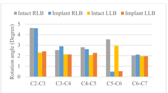
The ROM at the implanted segment was reduced by 38% for flexion and it was increased by 39% for the extension. Besides this the change in ROM at other segments was less than 2%. For lateral bending the ROM was increased by 14% at the C3-C4 level during the right lateral bending (RLB) and the change in ROM stayed within 10% for the other segments except for the implanted segment as the ROM was decreased by 86.2% in it. The reduction at the index segment further increased for axial rotation. Reduction of 88.45% and 90.84% was seen for right axial rotation (RAR) and left axial rotation (LAR) respectively. At the inferior and superior segment ROM was increased by 2.2% and 7.5% respectively.
IV. DISCUSSION
The aim of this finite element analysis was to study the effect of a U-Shaped implant. For this purpose, physiological model of cervical spine from C2-C7 was used and the implant was implanted between C5-C6 and coupled with them. After obtaining the results and comparing it with the intact model we deduce that the implant did not affect the ROM of adjacent segments greatly. However, the results were not promising for the index segment during axial rotation and lateral bending. This study is based on flexibility test method i.e. the pure bending moment is applied and the ROM is calculated [2]. In order to have better insights regarding the functioning of dynamic stabilization system hybrid testing method can be used as proposed by Panjabi et al [3]. This study had limitations due to the nature of computational methods. Moreover, the attributes of spine are also dependent on the age factor which cannot be addressed completely in FE studies. Despite these limitations, FE studies are able to provide acceptable results and with the advancements in computational technology, FE studies will be able to mimic the real life scenario more accurately in near future.
(a)
(b) (c)
Figure 1. a) Cervical Spine FE model with an implant, b) Cross sectional view of C5-C6 with implant, c) U-Shaped Implant
Figure 2.Comparasion of ROM with and without implant in flexion-extention. 0 2 4 6 8 10 C2-C3 C3-C4 C4-C5 C5-C6 C6-C7 R ot at io n an gl e (D eg re e)
Figure 3.Comparasion of ROM with and without implant for lateral bending.
Figure 4.Comparasion of ROM with and without implant for axial rotation.
REFERENCES
[1] Erbulut DU, Zafarparandeh I, Lazoglu I, Ozer AF: Application of an asymmetric finite element model of the C2-T1 cervical spine for evaluating the role of soft tissues in stability. Medical Engineering & Physics 2014.
[2] Goel VK, Panjabi MM, Patwardhan AG, Dooris AP, Serhan H Test protocols for evaluation of spinal implants. J Bone Joint Surg 88:103–109, (2006).
[3] Panjabi MM. Hybrid multidirectional test method to evaluate spinal adjacent-level effects. Clin Biomech. 22:257-65, 2007.
0 1 2 3 4 5 C2-C3 C3-C4 C4-C5 C5-C6 C6-C7 R ot at io n an gl e (D eg re e)
Intact RLB Implant RLB Intact LLB Implant LLB
0 2 4 6 8 10 12 14 C2-C3 C3-C4 C4-C5 C5-C6 C6-C7 R ot at io n an gl e (D eg re e)