MODEL-DRIVEN ENGINEERING OF
SOFTWARE ARCHITECTURE VIEWPOINTS
A THESIS
SUBMITTED TO THE DEPARTMENT OF COMPUTER ENGINEERING AND THE GRADUATE SCHOOL OF ENGINEERING AND SCIENCE
OF BILKENT UNIVERSITY
IN PARTIAL FULFILLMENT OF THE REQUIREMENTS FOR THE DEGREE OF
MASTER OF SCIENCE
By Elif Demirli September, 2012
ii
I certify that I have read this thesis and that in my opinion it is fully adequate, in scope and in quality, as a thesis for the degree of Master of Science.
______________________________ Asst. Prof. Dr. Bedir Tekinerdoğan (Supervisor)
I certify that I have read this thesis and that in my opinion it is fully adequate, in scope and in quality, as a thesis for the degree of Master of Science.
______________________________ Prof. Dr. Özgür Ulusoy
I certify that I have read this thesis and that in my opinion it is fully adequate, in scope and in quality, as a thesis for the degree of Master of Science.
______________________________ Asst. Prof. Dr. Kayhan İmre
Approved for the Graduate School of Engineering and Science:
_______________________________ Prof. Dr. Levent Onural
iii
ABSTRACT
MODEL-DRIVEN ENGINEERING OF SOFTWARE
ARCHITECTURE VIEWPOINTS
Elif Demirli
M.S. in Computer Engineering
Supervisor: Asst. Prof. Dr. Bedir Tekinerdoğan September, 2012
A common practice in software architecture design is to apply so-called architectural views to design software architecture for the various stakeholder concerns. Architectural views are usually developed based on architectural viewpoints which define the conventions for constructing, interpreting and analyzing views. So far most architectural viewpoints seem to have been primarily used either to support the communication among stakeholders, or at the best to provide a blueprint for the detailed design.
In this thesis, we provide a software language engineering approach to define viewpoints as domain specific languages. This enhances the formal precision of architectural viewpoints and leads to executable views that can be interpreted and analyzed by tools. We illustrate our approach for defining domain specific languages for the viewpoints of the Views and Beyond framework. The approach is implemented as an Eclipse plug-in, SAVE-Bench tool, which can be used to define different views based on the predefined software architecture viewpoints. The tool also supports automatic generation of architecture documentation from view models.
Keywords: Software Architecture Viewpoints, Software Language Engineering, Domain-Specific Modeling, Model-Driven Engineering, Tool Support.
iv
ÖZET
YAZILIM MİMARİSİ BAKIŞ AÇILARI İÇİN MODEL
GÜDÜMLÜ MÜHENDİSLİK
Elif Demirli
Bilgisayar Mühendisliği, Yüksek Lisans Tez Yöneticisi: Yrd. Doç. Dr. Bedir Tekinerdoğan
Eylül, 2012
Yazılım mimarisi tasarımında yaygın pratiklerden biri yazılım mimarisini çeşitli paydaş ilgilerine yönelik tasarlayabilmek için mimari görünümlerini kullanmaktır. Mimari görünümleri genellikle bu görünümleri oluşturmayı, yorumlamayı ve analiz etmeyi sağlayan kuralları tanımlayan mimari bakış açılarını temel alarak geliştirilir. Şimdiye kadar çoğu mimari bakış açısının esasen paydaşlar arasındaki iletişimi desteklemek ya da en iyi ihtimalle detaylı tasarım için bir plan sağlamak amacıyla kullanıldığı görülmektedir.
Bu tezde mimari bakış açılarını alana özgü dil olarak tanımlamak için bir yazılım dil mühendisliği yaklaşımı sunuyoruz. Bu, mimari bakış açılarının formalliğini iyileştirirken bir yandan da araçlar tarafından yorumlanıp analiz edilebilen çalıştırılabilir görünüm modellerine öncülük ediyor. Mimari bakış açılarını alana özgü dil olarak tanımlama çalışmamızı Görünümler ve Ötesi yaklaşımı için gösterdik. Yaklaşımımız çeşitli görünümleri modellemeyi destekleyen Eclipse eklentisi SAVE-Bench yazılım aracı olarak geliştirildi. Araç aynı zamanda görünüm modellerinden otomatik mimari dökümantasyonu üretmeyi de destekliyor.
Keywords: Yazılım Mimari Bakış Açıları, Yazılım Dil Mühendisliği, Alana-Özgü Modelleme, Model Güdümlü Mühendislik, Araç Desteği.
v
Acknowledgement
I would like to express my sincere gratitude to my supervisor Asst. Prof. Dr. Bedir Tekinerdoğan for his invaluable guidance, support and understanding during this thesis. He encouraged and motivated me during my whole research.
I am thankful to Prof. Dr. Özgür Ulusoy and Asst. Prof. Dr. Kayhan İmre for kindly accepting to be in the committee and also for giving their precious time to read and review this thesis.
I am grateful to The Scientific and Technological Research Council of Turkey (TÜBİTAK-BİDEB) for the financial support they provided during the time span of this thesis.
I would like to thank to my housemate Özlem, my friends Seher, Şadiye, Püren and Başak for their valuable friendship and the enjoyable time we spent together. Last but not least, I would like to thank my family, my mother Makbule, my father Ekrem and my sister Esra for being in my life, for their endless, unconditional love and support to me. With very special thanks, I dedicate this thesis to them.
vi
Contents
1 Introduction ... 1
1.1. Software Architecture Design ... 1
1.2. Problem Statement ... 3
1.3. Approach ... 4
1.4. Contribution ... 6
1.5. Outline of the Thesis ... 7
2 Software Architecture Views ... 8
2.1. Background ... 8
2.2. Software Architecture Frameworks ... 10
2.3. Enterprise Architecture Frameworks ... 13
3 Model-Driven Development ... 16
3.1. Modeling ... 17
3.2. Meta-Modeling ... 18
3.3. Model Transformations ... 21
4 Domain Specific Languages for Software Architecture Viewpoints ... 24
4.1. Viewpoints as Metamodels ... 25
4.2. Case Study: Crisis Management System ... 28
4.3. Domain Specific Languages for V&B Framework ... 29
4.3.1. Module Viewpoints ... 30 4.3.1.1. Decomposition Viewpoint ... 30 4.3.1.2. Uses Viewpoint ... 32 4.3.1.3. Generalization Viewpoint ... 35 4.3.1.4. Layered Viewpoint ... 38 4.3.1.5. Aspects Viewpoint ... 42
4.3.1.6. Data Model Viewpoint ... 44
4.3.2. Component and Connector Viewpoints ... 46
4.3.2.1. Pipe and Filter Viewpoint ... 46
4.3.2.2. Shared Data Viewpoint ... 50
4.3.2.3. Publish-Subscribe Viewpoint ... 52
vii 4.3.2.5. Peer-to-Peer Viewpoint ... 56 4.3.2.6. SOA Viewpoint ... 58 4.3.3. Allocation Viewpoints ... 60 4.3.3.1. Deployment Viewpoint ... 60 4.3.3.2. Install Viewpoint ... 63
4.3.3.3. Work Assignment Viewpoint ... 64
4.4. Evaluation of Architectural Viewpoint Frameworks ... 65
4.4.1. Evaluation Framework ... 66
4.4.2. Evaluation of Views and Beyond Framework ... 70
5 SAVE-Bench Tool ... 74
5.1. Save-Bench Architecture ... 74
5.2. Using Save-Bench ... 77
6 Automatic Architecture Document Generation ... 82
7 Related Work ... 88
8 Conclusions ... 92
Bibliography ... 94
viii
List of Figures
2.1. IEEE conceptual model for architecture description ... 9
2.2 Kruchten’s 4+1 viewpoint framework ... 11
3.1. An example for the four-layer OMG architecture ... 20
3.2. A conceptual model to describe metamodeling concepts... 21
4.1. Architectural Description Concepts from a meta-modeling perspective ... 25
4.2. The process of defining DSLs for architectural viewpoints ... 27
4.3. Abstract syntax and grammar for decomposition style ... 31
4.4. Textual decomposition view model... 31
4.5. Visual decomposition view model ... 32
4.6. Abstract Syntax of Uses Viewpoint ... 33
4.7. Grammar of Uses Viewpoint ... 33
4.8. Textual Uses View ... 34
4.9. Visual uses view ... 34
4.10. Abstract syntax for generalization viewpoint ... 36
4.11. Grammar for generalization viewpoint ... 37
4.12. Textual generalization view ... 37
4.13. Visual generalization view ... 38
4.14. Abstract syntax for layered viewpoint ... 39
4.15. Grammar for layered viewpoint ... 40
4.16. Textual layered view ... 40
4.17. Visual layered view ... 41
4.18. Abstract syntax for aspects viewpoint ... 43
4.19. Grammar for aspects viewpoint ... 43
4.20. Textual aspects view... 44
4.21. Abstract syntax for data model viewpoint ... 45
4.22. Grammar for data model viewpoint ... 45
4.23. Textual data model view ... 46
4.24. Abstract syntax for pipe-and-filter style ... 47
4.26. Grammar for pipe-and-filter viewpoint ... 48
4.26. Textual pipe-and-filter view ... 49
ix
4.28. Abstract syntax and grammar for shared data viewpoint ... 51
4.29. Textual shared data view ... 52
4.30. Abstract syntax for publish subscribe viewpoint ... 53
4.31. Grammar for publish subscribe viewpoint ... 54
4.32. Textual publish-subscribe view ... 54
4.33. Abstract syntax for client-server viewpoint ... 55
4.34. Grammar for client-server viewpoint ... 56
4.35. Visual client-server view ... 56
4.36. Abstract syntax for peer-to-peer viewpoint ... 57
4.37. Grammar for peer-to-peer viewpoint... 58
4.38. Visual peer-to-peer view ... 58
4.39. Visual SOA view ... 60
4.40. Abstract syntax for deployment viewpoint ... 61
4.41. Grammar for deployment viewpoint ... 61
4.42. Textual and visual deployment views ... 62
4.43. Abstract Syntax for install viewpoint ... 63
4.44. Grammar for install viewpoint ... 63
4.45. Visual install view ... 64
4.46. Abstract syntax for work allocation view ... 65
4.47. Grammar for work allocation view ... 65
4.48. Overall Process for Assessment of Architectural Viewpoint ... 67
4.49. Activity Diagram for Activity Model Viewpoint ... 68
4.50. Abstract syntax definition levels for V&B (both editions of the book) ... 71
4.51. Concrete syntax definition levels for V&B (both editions of the book) ... 72
4.52. Static semantics definition levels for V&B (both editions of the book) ... 73
5.1. Process for defining Viewpoints as DSLs and generating SAVE-Bench ... 75
5.2. SAVE-Bench model file creation wizard ... 78
5.3. Snapshot of the SAVE-Bench tool for modeling architectural views ... 79
5.4. SAVE-Bench screenshot ... 81
6.1. Model-to-text transformation pattern for architecture documentation generation ... 83
6.2. Architecture documentation generation process ... 84
6.3. M2T transformation template for decomposition viewpoint ... 85
6.4. Decomposition view part of generated architecture documentation ... 86
6.5. M2T transformation template for pipe and filter viewpoint ... 87
1
Chapter 1
Introduction
1.1. Software Architecture Design
As the size and complexity of software systems increases, software architecture has emerged as an important sub-discipline of software engineering. A software architecture for a program or computing system consists of the structure or structures of that system, which comprise elements, the externally visible properties of those elements, and the relationships among them [6]. Since it depicts the high-level structure of the system, software architecture is a valuable artifact for both communicating and designing the system. Representing a common abstraction of a system, software architecture forms a basis for understanding and communication among stakeholders who have various concerns in the construction of the software system. In addition to this, as one of the earliest artifact of the software development life cycle, software architecture embodies early design decisions, which impacts the system’s detailed design, implementation, deployment and maintenance. That is why; it must be carefully documented and analyzed.
Software architecture is not a single one-dimensional structure but it consists of a set of structures. This can be better explained via house architecture analogy. In
2
order to build a house and reason about its architecture, every stakeholder of the house either uses or creates a particular plan that satisfies his own interests. The house architect designs the skeleton of the house. Interior designer defines the interior architecture plan and the electrician sets up wiring plan based on the house architect’s plan. All of these plans are different entities and every stakeholder is interested in a few of them. Individually, none of those plans can be called as house architecture. However, when all of them are brought together, they constitute the architecture of the house. The same situation applies in software development, too. A software system has a set of stakeholders who have special interests on the overall system. A software developer is interested in how the system is structured as a set of implementation units, a performance engineer is interested in the organization of the run-time elements and a project manager is concerned about the distribution of implementation units among development teams. Each of these structures is a part of the software architecture, however; none of them can be called as software architecture by itself. In order to enable dealing with those different structures easily architectural view concept was introduced.
An architectural view is a representation of a set of system elements and relations associated with them to support a particular concern [6]. Each view shows the system from a different point of view. Having multiple views helps to separate the concerns and as such support the modeling, understanding, communication and analysis of the software architecture for different stakeholders. The conventions for constructing and using a view are specified by viewpoints [6]. Viewpoints basically define element and relation types that can be used for the corresponding view, together with some set of constraints on their use. An architectural framework organizes and structures the proposed architectural viewpoints. Different architectural frameworks have been proposed in the literature. Examples of architectural frameworks include the Kruchten’s 4+1 view model [24], the Siemens Four View Model [17], and the Views and Beyond approach (V&B) [6][7].
3
1.2. Problem Statement
Obviously the notion of architectural view plays an important role in modeling and documenting architectures. Architectural views are intended to be used for communication, design and analysis. The quality, expressiveness and value of view models are based on the corresponding viewpoint definitions. When examined, it is observed that so far most architectural viewpoints seem to have been primarily used either to support the communication among stakeholders, or at the best to provide a blueprint for the detailed design. These viewpoints were defined in a notation and representation neutral manner to increase their use and flexibility. That is why; most viewpoint definitions are high-level and abstract. A comprehensive analysis and design process is required to develop tools for modeling viewpoint specifications. Consequently, the derivation of formal view models and performing formal analysis of the specifications produced becomes harder.
The lack of a formal approach for defining viewpoints results in less precise viewpoint definitions. From a historical perspective it can be observed that viewpoints defined later are more precise and consistent than the earlier approaches but a close analysis shows that even existing viewpoints lack some precision. Moreover, since existing frameworks provide mechanisms to add new viewpoints the risk of introducing imprecise viewpoints is high. The development of a proper and effective architecture is highly dependent on the corresponding documentation. An incomplete or imprecise viewpoint will impede the understanding and application of the viewpoints to derive the corresponding architectural views, and likewise lower the quality of the architectural document. The resulting view models lead ambiguous interpretations.
When the function of architectural views in software development lifecycles is examined, we observe that architectural views are not single isolated artifacts. They have relations both among themselves and to other software development artifacts. In order to enable consistency and automation among those artifacts, executable view models are required. When current view modeling practices are
4
analyzed, we observe that view models are not at the desired level of formality. The reason behind it is the lack of formal viewpoint definitions on top of which formal and automatically processable executable view models can be defined. In addition to these, since the language to define views, namely viewpoints, are not formally defined, developing a tool support for view modeling requires heavyweight analysis step to lift viewpoint definitions up to proper level of formality. In the literature, there is not much architecture modeling tools that puts architectural views at the center. This lack leads view modelers to simple box-and-line diagrams which is not a healthy way since the ambiguities in notation can cause misinterpretations.
In summary, we have identified the following problems in current architecture view modeling practices:
Lack of formal approach for defining viewpoints
Imprecise and vague viewpoint definitions in the literature
Lack of tool support
1.3. Approach
In order to address above problems, we propose that viewpoints should be also defined as formal languages. We recognize that viewpoints are in fact metamodels and we provide a Model Driven Engineering (MDE) approach for defining viewpoints as domain specific languages (DSLs). This enhances the formal precision of architectural viewpoints and likewise helps to share the additional benefits of domain specific languages, i.e. defining executable views.
First, we identified that viewpoints are in fact domain specific languages. A domain specific language is an executable specification language that offers proper abstractions and notations for expressing a particular problem domain [8]. Viewpoints are DSLs since they provide particular abstractions and notations for specific stakeholder concerns. We selected Views and Beyond architecture framework to show our process of defining DSLs for viewpoints. We recognize
5
viewpoints as DSLs that is why we develop metamodel for each viewpoint. In both software language engineering and model-driven development domain, a metamodel is defined as follows:
1) Definition of abstract syntax: Abstract syntax describes the vocabulary of concepts provided by the language and how they may be combined to create models. In order to define abstract syntax for viewpoint DSLs, we first needed to identify language constructs that will be used in modeling views. We analyzed the current viewpoint definitions to define the vocabulary of our DSLs. We observe that most viewpoint definitions in Views and Beyond Framework are not at the desired level of formality to map them easily to language. We filled out the missing parts and resolved inconsistencies in language constructs when required. After deciding the language constructs and their interrelations, we define grammar for the viewpoint using Eclipse Xtext tool [37]. Grammar encapsulates the abstract syntax in itself.
2) Definition of concrete syntax: Concrete syntax defines the notation that facilitates presentation and construction of models. We define both textual and visual concrete syntax for viewpoints. Textual concrete syntax is embedded in grammar definition. We use Eclipse GMF tools [16] and other supplementary Eclipse plug-ins to define visual concrete syntax. In our analysis on current viewpoint definitions, we observe that usually formal notations or modeling tools are not provided. We make use of the informal and semi-formal notations provided and define our own notation on top of them.
3) Definition of static semantics: Static semantics, namely well-formedness rules, provide definition of additional constraint rules on abstract syntax that are hard or impossible to express in standard syntactic formalism of the abstract syntax. In viewpoint definitions of Views and Beyond approach, these constraints are listed as topology constraints. We analyzed them and observed that they are mostly incomplete constraints in natural language. We lift them up to executable constraints embedding them into our DSL definitions as validation codes written in Java.
6
4) Definition of semantics: Semantics is the description of the meaning of the concepts in the abstract syntax. In this work, we don’t provide formal semantic specifications. We keep it out of the scope of this thesis.
We followed these steps to define metamodels for the selected viewpoints. We illustrate our approach in a generic way through the thesis such that it can be applied on other viewpoint frameworks. We used various Eclipse tools in our work and present our formal viewpoint specifications as Eclipse plug-ins in our tool SAVE-Bench. SAVE-Bench consists of domain specific languages for Views and Beyond framework viewpoints and it enables modeling textual and visual views that conforms to those viewpoints. It also supports automatic architecture documentation from view models.
1.4. Contribution
The contributions of this thesis can be defined as follows:
Systematic approach for modeling architectural viewpoints as DSLs and executable models for the Views and Beyond approach
We recognized the lack of a formal approach for defining architectural viewpoints. The key premise of this work is recognizing that viewpoints are in fact domain specific languages. We present our software language engineering approach explicitly through the thesis. We analyzed the V&B framework viewpoints and concluded that the viewpoint definitions are not at the desired level of formality to support executable view models. We enhanced those viewpoint definitions and present them in SAVE-Bench tool in order to enable modeling executable views.
Evaluation framework for characterizing viewpoint approaches
In order to evaluate the formality of the viewpoint definitions, we set up an evaluation framework. The framework evaluates the viewpoint definitions from software language engineering perspective with respect to their completeness and degree of formality. We provide evaluation results for V&B viewpoint definitions and observed that viewpoints defined earlier are less precise than those defined
7
later. We also see how our viewpoint DSLs lift the formality and precision of viewpoint definitions up.
SAVE-Bench Eclipse Plug-in tool for modeling software architecture viewpoints
We collected our formal viewpoint definitions for V&B in SAVE-Bench tool. The tool enables defining executable view models using DSLs for viewpoints. It is extensible such that new viewpoint frameworks can be added or new viewpoints can be defined as DSLs into existing frameworks. The tool also supports automatic architecture document generation from view models.
1.5. Outline of the Thesis
This thesis is organized as follows: Chapter 2 provides background information for software architecture views and presents the widely used viewpoint frameworks. Chapter 3 provides an overview of model-driven development. In Chapter 4, first, the idea that viewpoints are in fact domain specific languages is introduced. Case description is provided which will be used as example for modeling views. Then, the domain specific languages for the viewpoints defined in Views and Beyond framework are provided and evaluated with respect to a viewpoint evaluation framework. Chapter 5 presents the SAVE-Bench tool that we have developed for modeling viewpoints and based on these the views. In Chapter 6, automatic architecture documentation from architectural view models is explained. Chapter 7 gives the related work. Finally, Chapter 8 presents the conclusions and discussions.
8
Chapter 2
Software Architecture Views
Software architecture for a computing system is the structure or structures of that system, which consists of elements, their externally visible properties and relationships among them [6]. As this definition implies, software architecture is not a single structure, but it consists of lots of overlaying structures. In order to ease dealing with those structures separately, architectural view concept was introduced. In this section, we will present the background information on architectural views. Then, we will introduce some selected software architecture and enterprise architecture frameworks that enables modeling the architecture using views.
2.1. Background
Architectural drivers define the concerns of the stakeholders which shape the architecture. A stakeholder is defined as an individual, team, or organization with interests in, or concerns relative to, a system. Each of the stakeholders’ concerns impacts the early design decisions that the architect makes [6][20]. A common practice is to model and document different architectural views for describing the architecture according to the stakeholders’ concerns. An architectural view is a representation of a set of system elements and relations associated with them to
9
support a particular concern [7]. Having multiple views helps to separate the concerns and as such support the modeling, understanding, communication and analysis of the software architecture for different stakeholders.
Architectural views are defined based on viewpoints. An architectural viewpoint is a specialization of element and relation types together with a set of constraints on how they can be used [7]. The view and viewpoint concepts are directly addressed in IEEE 1471 standard [20]. Viewpoints encapsulate some design knowledge that addresses a set of stakeholders’ concerns. They are independent of systems. When a viewpoint is bound to a system, the resulting model is architectural view of the system. The conceptual model from IEEE 1471 standard describing architectural view and viewpoint concepts are given in Figure 2.1 [20]. As shown in the figure, each architectural view addresses some stakeholders concerns and these concerns also directly affect the viewpoint definitions. Viewpoint definitions are important assets here since they differentiate architectural views to address different concerns.
10
A viewpoint framework collects and organizes a set of viewpoints to guide the architect [20]. Initially, viewpoint frameworks were introduced as a collection of fixed set of viewpoints to document the architecture. For example, the Rational’s Unified Process [], which is based on Kruchten’s 4+1 view approach [24] utilizes the logical view, development view, process view and physical view. Lately, this situation has changed. Because of the different concerns that need to be addressed for different systems, the current trend recognizes that the set of views should not be fixed but multiple viewpoints might be introduced instead. For this reason, the IEEE 1471 standard [20] does not commit to any view although it takes a multi-view approach for architectural description.
2.2. Software Architecture Frameworks
Kruchten’s 4+1 Viewpoint Framework
Philippe Kruchten’s 4+1 set which forms a basis for Rational’s Unified Process [] can be seen as the first formal software architecture viewpoint framework in the literature. It describes five different viewpoints to model software architectures. Figure 2.2 shows the views of Kruchten’s framework. Logical view can be seen as a kind of object model of the architecture. It is used to support the concerns related to functional requirements. Process View takes into account the non-functional requirements such as performance and availability. It captures the concurrency and synchronization aspects of the design. Physical view describes the environment in which software executes and shows the mappings of software onto the hardware. Development view presents the static organization of the software in its development environment. According to Kruchten, architecture can be organized around these four views. However, a supplementary view (i.e. scenarios) is required to complete the architectural description. This final +1 view serves as glue among other views that ensures the elements of other views work together in harmony.
11
Figure 2.2 Kruchten’s 4+1 viewpoint framework Siemens Four View Framework
Siemens four view framework is a result of a study into the industrial practices of software architecture [17]. The authors found that the structures used to design and document software architecture fall into four broad categories, which they call conceptual, module, execution and code structures. Each category addresses different stakeholder concerns.
The views in Siemens Four View framework are not single, isolated models, but several important mappings of structures are explicitly defined in the design approach. The elements of conceptual view are “implemented-by” module view structures, and also “assigned-to” execution view structures. Module view elements can be “located-in” or “implemented-by” code view elements. Code structures can configure execution structures. In other words, there is a strict relation between different views of Siemens Four View framework. Changing the structure or definition of a view will most probably require updating another view. Rozanski and Woods Framework
Rozanski and Woods [34] address the architecture of large information systems and propose six core viewpoints: Functional, Information, Concurrency, Development, Deployment and Operational.
12
Functional viewpoint describes the system’s runtime functional elements and their responsibilities, interfaces and primary interactions. Its main concerns are functional capabilities and internal structure of the system. As the name implies, information viewpoint mainly concerns the information structure of the system. It is used to describe the way that architecture stores, manipulates and distributes information. Concurrency viewpoint is used to address the concurrency structure of the system. It shows how functional elements are mapped on concurrency units such as threads and processes in order to clearly identify the parts that can execute concurrently. Development Viewpoint addresses software developers’ and testers’ concerns such as module organization, codeline organization, standardization of design and testing. Deployment Viewpoint is used to describe the runtime environment into which the system will be deployed. Finally, operational viewpoint describes how the system will be operated, administrated and supported when it is running in its production environment.
Views and Beyond Framework
Views and Beyond framework[6][7] is an open-ended viewpoint framework. Being open-ended framework means that the framework does not limit the number of viewpoints that are defined, any new viewpoints can be introduced. They do not use the term viewpoint explicitly; they refer to it as style. A style definition provides the elements and relation types to be used when defining views together with some topological constraints. In V&B framework, there is no limit on the number of styles that can be defined. There is a set of predefined styles that are organized around three main types of architectural styles: Module styles, component-and-connector styles and allocation styles. Module styles are used to show how the system is structured as a set of implementation units. Decomposition style is an example to module styles which shows the structure of modules and submodules. Component and connector styles are used to show how the system is structures as a set of runtime elements. Pipe-and-filter style is an example to this which shows the data flow between so-called filters that manipulate the data. Allocation styles are used to show how the software elements are mapped to non-software elements in its environment. Deployment style is an
13
example to allocation styles and it is used to show how the software elements are mapped on hardware elements and their run-time behavior.
2.3. Enterprise Architecture Frameworks
RM-ODP
Reference Model of Open Distributed Processing (RM-ODP) is a reference model which provides a framework for the standardization of open distributed processing [19]. It provides an enterprise architecture framework which comprises five generic and complementary viewpoints on the system and its environment. The enterprise viewpoint focuses on the purpose, scope and policies for the system. It describes the business requirements and how to meet them. Information viewpoint focuses on the semantics of the information and information processing performed. It describes the information managed by the system. The computational viewpoint enables distribution through functional decomposition on the system into objects which interacts at interfaces. It describes the functionality provided by the system and its functional decomposition. The engineering viewpoint focuses on the mechanism and functions required to support distributed interactions between objects in the system. Technology viewpoint describes the technologies chosen to provide the processing, functionality and presentation of the information.
Each viewpoint is explicitly specified by a language that defines concepts and rules for specifying ODP systems from the corresponding viewpoints. In addition to this, a UML profile is provided for each viewpoint language.
Zachman’s Framework
The Zachman Framework is an enterprise architecture framework which provides a formal and highly structured way of viewing and defining an enterprise [39]. The basic idea behind Zachman’s framework is that an item can be described using different ways for different purposes. The framework consists of a two
14
dimensional matrix based on the intersection of six questions and six particular perspectives namely views.
The rows of the framework are as following: Row 1 describes the scope of the system. It is the planner’s view of the architecture which is an executive summary for planner and investor who wants to estimate the cost and scope of the system. Row 2 is owner’s view which corresponds to enterprise models that shows business entities, processes and their interrelationships. Row 3 is designer’s view which shows data elements, logical process flows and functions. Row 4 is builder’s view which is a more specific version of designer’s view. The elements of designer’s view are bound to supporting technology for example the programming language that is used. Row 5 is subcontractor view which is a detailed specification of the system that is given to programmers who implement individual modules without knowing the overall structure of the system.
Each row in the framework can be described in 6 different representations: data description (what), function description (how), network description (where), people description (who), time description (when), motivation description (why). TOGAF
The Open Group Architecture Framework is a framework for enterprise architecture which provides a high-level, comprehensive approach for designing, planning, implementation and governance of enterprise information architecture [37]. TOGAF’s taxonomy of architecture views defines the four categories of architectural views that should be considered in the development architecture. Business Architecture Views address the concerns of the users of the system. They describe the flows of business information between people and business processes. Data Architecture Views describes data entities and their interrelations addressing database designers’ and administrators’ concerns. Application Architecture Views provide blueprint for the system, its interactions to other systems. Technical Architecture Views describes the hardware, software and network infrastructure to support the application functionalities.
15
DoDAF
Department of Defense Architecture Framework (DoDAF) is an architecture framework that is targeted for United States Department of Defense that provides structure for a specific stakeholder through viewpoints organized by various views [9]. In DoDAF, architectural viewpoints are composed of data that has been organized to facilitate understanding. All Viewpoint describes the overarching aspects of architecture context that relate to all viewpoints. Capability Viewpoint articulates the capability requirements, delivery timing and deployed capability. Data and Information Viewpoint describes the data relationships in the architecture context of the architecture. Operational Viewpoint includes the operational scenarios, activities, and requirements that support capabilities. Project Viewpoint describes the relationships between operational and capability requirements. Services Viewpoint presents the design for solutions supporting operational and capability functions. Standards Viewpoint describes the operational, business, technical and industry policies, standards and constraints on system and service requirements. Systems Viewpoint describes the legacy support, the design for solutions articulating the systems, their interrelationships and compositions.
16
Chapter 3
Model-Driven Development
Historically, models have had a long tradition in software engineering and have been widely used in software projects. Software is a complex entity that is built upon both domain and technical knowledge. In order to be able to deal with only the relevant piece of the software at the desired level of abstraction, software researchers and developers create abstractions, namely models of the software. Initially, models had been treated as only documentation. Model-Based Software Development (MBSD) aims to use models to develop software, but, it puts them into a completely separate place from the code. Recently, Model-Driven Software Development (MDSD) [35] paradigm entered to the stage which adopts models as the basic abstraction of software development process. According to MDSD, models are not only documentation but they can also directly participate into the code via automatic transformations.
In this chapter, we present the background on Model-Driven Development (MDD). Section 3.1 explains the concept of model. Section 3.2 gives basic information about metamodeling and software language engineering. Section 3.3 reports the value of model transformations in MDD and explains the two types of transformations: Model-to-text (M2T) and model-to-model (M2M) transformations.
17
3.1. Modeling
Modeling is a ubiquitous activity that we can observe in many areas of the real life. In general sense, a model is a set of statements that are used to describe the system under study. From this definition, it can be inferred that primary purpose of modeling is describing the subject entity.
In the context of software engineering, there exist several definitions of model. Here, we present some selected definitions that are collected by Muller et al. [29].
Definition 1
A model is a simplification of a system built with an intended goal in mind. The model should be able to answer questions in place of the actual system. [3]
Definition 2
Models provide abstractions of a physical system that allow engineers to reason about that system by ignoring extraneous details while focusing on the relevant ones. [5]
Definition 3
A model is an abstraction of a (real or language based) system allowing predictions or inferences to be made. [25]
We can summarize from these definitions a model is an abstraction of system that aim to describe a system from a specific point of view, ignoring the
unnecessary details, providing a basis for communication and analysis. The
highlighted properties make models valuable in the context of software engineering context.
Models are different in quality and nature. Mellor et al. [28] makes a distinction between three kinds of models depending on their level of precision.
18
Models as Sketches
Model as a sketch are used to communicate ideas and do not give much detail of the system. Sketches are informal diagrams used to communicate ideas, explore alternatives or design in a collaborative manner. They are usually focused on some aspect of the system and are not intended to show every detail of it.
Models as Blueprints
Model as a blueprint describe the system in sufficient detail. A blueprint must be enough to a programmer to code a system. In the case of forward engineering, the details of the blueprint should be enough for a programmer to code the system. In the case of reverse engineering, the diagrams show all the details of a system in order to understand it better or to provide views of the code in a graphical form.
Models as Executables
Executable models are models that have everything required to produce desired functionality of a domain. They are more precise than sketches and blueprints. They can be compiled by model compilers. For example, in case of UML, executable UML means that UML can also be used as a programming language. When used in this form, the whole system is specified in the UML, the diagrams are the code, and they are compiled directly into executable binaries.
In model-driven software development the concept of models can be considered as executable models as defined by the above characterization of Mellor et al. []. This is in contrast to model-based software development in which models are used as blueprints at the most.
3.2. Meta-Modeling
Model-driven software development is a paradigm in which the concept of model is the key abstraction. In contrast to based software development, in model-driven software development models are not mere documentation but become “code” that are executable and that can be used to generate even more refined
19
models or code. MDSD aims to achieve this goal through defining models and metamodels as first class abstractions, and providing automated support using model transformations [14][28][34].
In the context of MDSD metamodeling plays a very important role. The language in which models are expressed is defined by metamodel. More precisely, a metamodel describes the possible structure of models in an abstract way. It defines the constructs of modeling language, their relationships, constraints and rules. A model is said to be an instance of a meta-model, or a model conforms to a meta-model. A meta-model itself is a model that conforms to a meta-meta-model, the language for defining meta-models. In model-driven development, models are usually organized in a four-layered architecture. The top (M3) level in this model is the so called meta-metamodel, and defines the basic concepts from which specific meta-models are created at the meta (M2) level. Normal user models are regarded as residing at the M1 level, whereas real world concepts reside at level M0
The four-layered architecture [30] can be explained better via the example in Figure 3.1. In the bottommost layer M0, the real concrete system to be described lies. In M1, the model layer, there is class diagram which is in fact a model of the real system. In metamodeling layer, the concepts to define a class diagram are presented. The language used for modeling the class diagram-UML lies in the M2 layer. The topmost layer is the meta-metamodeling layer which embodies the language for defining the metamodel, in this case UM which is meta-object facility(MOF). The topmost layer M3 is accepted to be recursively defined by itself.
20
Figure 3.1. An example for the four-layer OMG architecture
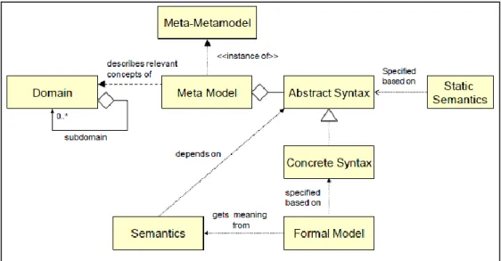
Metamodels are important concepts in not only MDSD domain but also in software language engineering (SLE) [23] which is defined as the application of a systematic, disciplined, quantifiable approach to the development, use, and maintenance of languages. A proper definition of meta-models is important to enable valid and sound models. In both the software language engineering [23] and model-driven development domains [35], a meta-model should include the following elements:
Abstract Syntax: describes the vocabulary of concepts provided by the language
and how they may be combined to create models. It consists of a definition of the concepts and the relationships that exist between concepts.
21
Concrete Syntax: defines the syntax, the notation that facilitates the presentation
and construction of models or programs in the language. Typically two basic types of concrete syntax are used by languages: textual syntax and visual syntax. A textual syntax enables models to be described in a structured textual form. A visual syntax enables a model to be described in a diagrammatical form.
Well-formedness rules (Static Semantics): provides definitions of additional
constraint rules on abstract syntax that are hard or impossible to express in standard syntactic formalisms of the abstract syntax.
Semantics: The description of the meaning of the concepts and relation in the
abstract syntax. Semantics can be defined in natural language or using other more formal specification languages.
Figure 3.2 shows the elements that constitutes a metamodel and their relationships.
Figure 3.2. A conceptual model to describe metamodeling concepts.
3.3. Model Transformations
The notion of model transformation is central to model-driven engineering [28][35]. Amodel transformation takes a model conforming to a given metamodel
22
as input and produces another model as output which also conforms to a given metamodel. Model transformations are useful for the following purposes:
Generating lower-level models, eventually code, from higher level models
Ensuring that a family of models is consistent, saving effort and reducing errors by automating the building and modification of models where possible
Mapping and synchronizing among models at the same level of different levels of abstraction
Reverse engineering of higher-level models from lower-level models or code.
Figure 3.3 explains basic model transformation pattern [35]. Source model is defined based on the source metamodel. There is also a given target metamodel. Transformation definition defines how a model conforming to source metamodel can be translated to an output model conforming to the target metamodel. The transformation definition is executed by a transformation engine. It reads the source model and outputs the target model. The transformation can be unidirectional or bidirectional based on the transformation definition.
23
Basically models transformations are categorized into two types: model-to-model and model-to-text transformations.
Model-to-Model (M2M) Transformation: In model-to-model transformation a
model is transformed into another model (target model) which is instance of either the source metamodel or another metamodel. Both input and output are models which conforms to some metamodel. Transformation rules are defined to support M2M transformations and they are executed by transformation engine. Based on the definition of those rules, transformation can be unidirectional or bidirectional. The Eclipse M2M project provides a framework for model-to-model transformation languages including ATL[22], Operational QVT and Relational QVT [31]. Model-to-model transformation is required to ease generation of intermediate software models and keeping all models consistent.
Model-to-Text(M2T) Transformation: Model-to-text transformation which is
also referred as model-to-code transformation is a special case of model-to-model transformation in which there is no target metamodel and the target output is a text. Model-to-text transformations are useful generating textual artifacts like code and documentation. It is standardized how to translate a model to various texts such as code, specifications, reports and documents in MOF Model to Text standard. Essentially, the standard needs to address how to transform a model into a linearized text representation. A template-based approach is defined in which the text to be generated from models is specified as a set of text templates that are parameterized with model elements. In the literature, there exists various tools that support model-to-text transformations that are developed based on MOF M2T standard such as Acceleo [1] and Xpand [38].
24
Chapter 4
Domain-Specific Languages for
Software Architecture Viewpoints
Architectural views are usually developed based on architectural viewpoints which define the conventions for constructing, interpreting and analyzing views. Our analysis on the architectural viewpoints yields that so far most architectural viewpoints seem to have been primarily used either to support the communication among stakeholders, or at the best to provide a blueprint for the detailed design. They are not used as, executable architectural models. We identified that one important reason behind this is that the architectural viewpoints in the literature are not well and precisely defined. In order to address this problem, we propose that architectural viewpoints should be defined as domain-specific languages (DSL). In this chapter, we provide a software language engineering approach to define viewpoints as domain specific languages. We illustrate our approach with the viewpoints of the Views and Beyond framework using Crisis Management System (CMS) architecture as the case study. We also set up a framework to evaluate the quality of the viewpoint definitions. After defining all viewpoints as DSLs, we illustrate how the current viewpoint definitions are improved when they are defined as DSLs using the evaluation framework.
25
4.1. Viewpoints as Metamodels
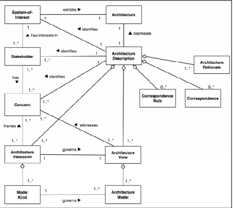
In architecture modeling literature the notion of meta-model is not explicitly used. Nevertheless, the concepts related to architectural description are formalized and standardized in ISO/IEC 42010:2007, a fast-track adoption by ISO of IEEE-Std 1471-2000, Recommended Practice for Architecture Description of Software-Intensive Systems [20]. The standard holds that an architecture description consists of a set of views, each of which conforms to a viewpoint, but it has deliberately chosen not to define a particular viewpoint. Here the concept of view appears to be at the same level of to the concept of model in the model-driven development approach. The concept of viewpoint, representing the language for expressing views, appears to be on the level of meta-model.
M0 M1 M2 Architecture Framework Architecture Viewpoint Architectural View System-of-Interest Architecture Architectural Description 1..* governs conforms to describes has 1..* 1..*
Figure 4.1. Architectural Description Concepts from a meta-modeling perspective
Although the ISO/IEC 42010 standard does not really use the terminology of model-driven development the concepts as described in the standard seem to align with the concepts in the meta-modeling framework. In Figure 4.1, we provide a
26
partial view of the standard that has been organized around the meta-modeling framework. An Architecture Description is a concrete artifact that documents the Architecture of a System of Interest. The concepts System-of-Interest and Architecture reside at layer M0. System-of-Interest defines a system for which an Architecture is defined. Architecture is described using Architectural Description that resides at level M1. Architectural Description includes one or more Architectural Views that represent the system from particular stakeholder concern’s perspective. Architectural views are described based on Architectural Viewpoint, the language for the corresponding view. Architectural Viewpoints are organized in Architectural Framework. The latter two reside at level M2. The standard does not provide a concept that we could consider at level M3, and as such we have omitted this in Figure 4.1.
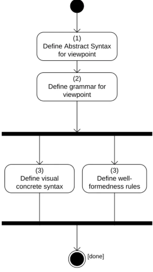
The key premise of this thesis is viewing the architectural viewpoints as metamodel. We build our work on top of this. As we mentioned in Chapter 3, a metamodel in other words a domain-specific language consists of the following elements: abstract syntax, concrete syntax, static semantics and semantics. We keep semantics discussion out of the scope of the thesis and follow the process shown in Figure 4.2 to define DSLs for architectural viewpoints. The formal viewpoint definitions given in Chapter 4.3 are defined based on this process. As we mentioned earlier, we selected Views and Beyond framework viewpoints to defined them as DSLs. For each DSL, we first present the abstract syntax that defines the language abstractions and their relationship. The abstract syntax for a viewpoint is defined after an analysis of the viewpoint description in the corresponding textbook [7].
27
(1)
Define Abstract Syntax for viewpoint
(2) Define grammar for
viewpoint (3) Define well-formedness rules (3) Define visual concrete syntax [done]
Figure 4.2. The process of defining DSLs for architectural viewpoints Based on these descriptions and the defined meta-model we provide the grammar which defines syntactic rules of the language together with textual concrete syntax. The grammar is defined using Xtext a language development framework provided as an Eclipse plug-in [11]. The grammar of the language is defined in Xtext's [39] EBNF grammar language and the corresponding generator creates a parser, an AST-meta model (implemented in EMF) as well as a full-featured Eclipse Text Editor from that. After defining the grammar, we have our pure language at hand. We enrich our language defining visual concrete syntax and well-formedness rules. These two are not mandatory steps and none of them are prerequisite to each other. As shown in Figure 4.2, they can be done in parallel. The visual concrete syntax is defined using Graphical Modeling Framework (GMF) plug-in of Eclipse [16]. Constraints on viewpoint elements and relations are implemented as static semantics which is implemented writing validation codes in Java.
28
4.2. Case Study: Crisis Management System
In this section, we present the case study Crisis Management System (CMS) [21] for which we will define sample architectural views when illustrating our domain-specific languages for viewpoints in section 4.3.
A crisis management system is a software system that helps in:
identifying, assessing, and handling a crisis situation
by coordinating the communication between all parties involved in handling the crisis,
by allocating and managing resources,
and by providing access to relevant crisis-related information to authorized users.
The need for crisis management systems has grown significantly over time. In the context of CMS a crisis can be major event that affects various segments of society such as natural disasters, terrorist attacks or accidents. The role of crisis management system is to facilitate the process of resolving the crisis by coordinating the relevant parties.
A crisis management scenario is initiated by a crisis report from a witness at the scene. A coordinator, who is responsible for organizing all required resources and tasks, initiates the crisis management process. The coordinator has access to the camera surveillance system. If a crisis occurs in locations under surveillance, the crisis management system can request video feed that allows the coordinator to verify the witness information.
A super observer who is an expert depending on the kind of crisis, is assigned to the scene to observe the emergency situation and identify the tasks necessary to cope with the situation. The tasks are crisis missions defined by the observer. The coordinator is required to process the missions by allocating suitable resources to each task.
29
Depending on the type of crisis, human resources could include firemen, doctors, nurses, policemen, and technicians, and hardware resources could include transportation systems, computing resources, communication means, or other necessities like food or clothes. The human resources act as first-aid workers. Each first-aid worker is assigned a specific task which needs to be executed to recover from the abnormal situation. The workers are expected to report on the success or failure in carrying out the missions. The completion of all missions would allow the crisis to be concluded.
In summary, a crisis management system (CMS) should include the following functionalities:
Initiating a crisis based on an external input from a witness,
Processing a crisis by executing the missions defined by a super observer and then assigning internal and/or external resources,
wrapping-up and archiving crisis,
authenticating users,
handling communication between coordinator/system and resources.
4.3. Domain Specific Languages for V&B Framework
In this section we will illustrate the modeling of viewpoints as domain specific languages to show how existing viewpoints can be even further formally specified to lift these to the level of executable models. We implement V&B framework [7] viewpoints as DSLs.
We will follow the process as defined in Figure 4.2. For each DSL, we first present the abstract syntax that defines the language abstractions and their relationship. Then, we provide the grammar which defines syntactic rules of the language together with textual concrete syntax. While presenting the language for a viewpoint, we provide example textual and visual view models of Crisis Management System that are defined using our DSLs.
30
4.3.1. Module Viewpoints
4.3.1.1. Decomposition Viewpoint
The Decomposition viewpoint [7] is used to show how system responsibilities are partitioned across modules and how these modules are decomposed into submodules. The decomposition view of the architecture depicts the overall structure of the architecture which is reasonably decomposed into modular implementation units. It is regarded as a fundamental view of the architecture since it serves as an input for other views (e.g. work allocation view) and helps to communicate and learn the structure of the software.
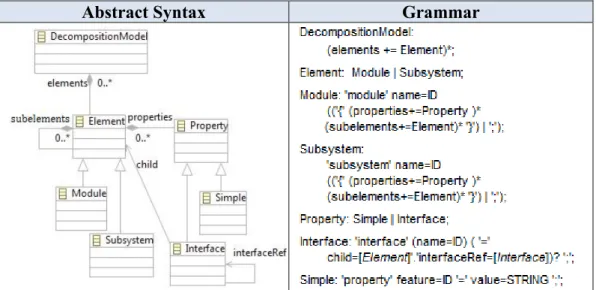
We have defined a DSL for decomposition viewpoint based on the textual specification given in [7]. The meta-model elements of it are provided below. A model of the abstract syntax for the decomposition style is given in the left part of Figure 4.3. The root element is DecompositionModel. A valid decomposition model consists of elements. An element can either be a Module or Subsystem. Module denotes principal unit of implementation. Subsystem differs semantically from the module in the way that it can be developed, executed and deployed independent of other system parts. The decomposition relation between elements is established via the aggregation relation indicating that an element consists of other subelements. Element can have two types of properties: Interface and Simple property. The element’s interface is documented with interface property. An element’s interface can be declared as a reference to one of its children’s interface. Simple property is a generic property which allows specifying new properties in view document.
The grammar for decomposition style is given in the right part of Figure 4.3. An example decomposition view implemented using our DSL is shown in Figure 4.4. The textual concrete syntax is defined for elements. No explicit relation is modeled in order to express decomposition. Subelements are directly placed into the parent element.
31
Abstract Syntax Grammar
Figure 4.3. Abstract syntax and grammar for decomposition style
Figure 4.4. Textual decomposition view model
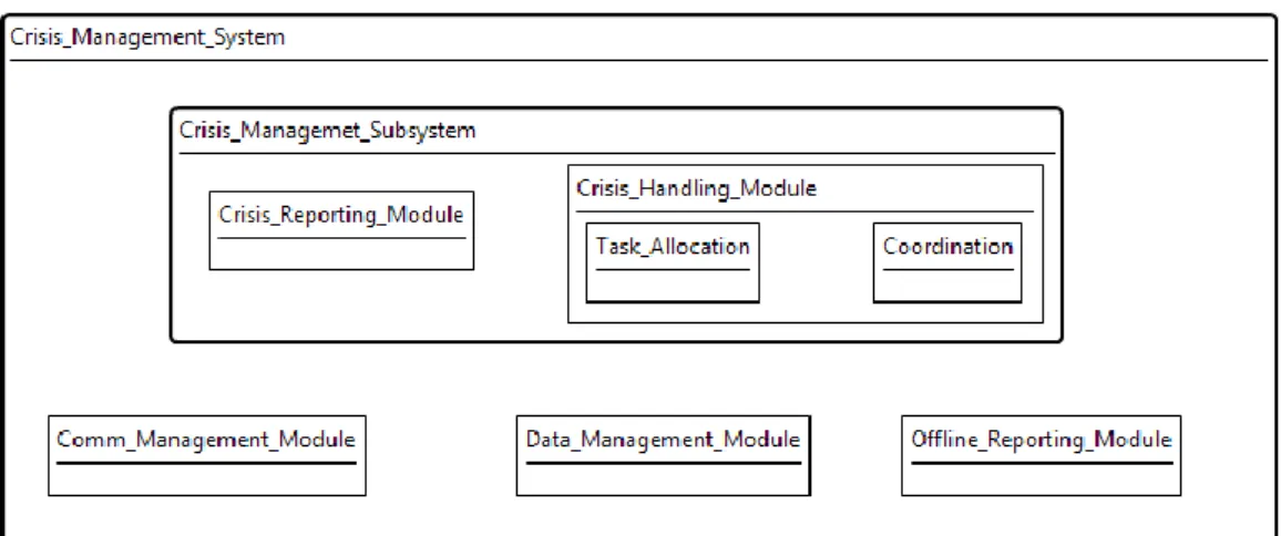
Crisis Management System consists of one large subsystem, Crisis Management Subsystem and supplementary modules where Comm Management module establishes the communication infrastructure for the system, Data Management module utilizes DBMS operations in a modular way and Offline Reporting module enables taking various reports on the crisis events. Crisis Management Subsystem consists of Crisis Reporting module which enables initiating and maintaining crisis management process in a well-formed documented way and Crisis Handling module which enables taking task allocation and coordination actions to resolve crisis situation. Both textual and visual decomposition view
32
models are easy-to-develop and understand. Visual view model for CMS decomposition viewpoint is given in Figure 4.5.
Figure 4.5. Visual decomposition view model
In addition to extracting the abstract syntax and the grammar we can also derive the well-formedness rules of views, the static semantics, from the viewpoint descriptions. In the decomposition style, two constraints have been defined: no loops are allowed in decomposition graph and a module can have only one parent. From the language perspective, those constraints are too high level to implement. We merged these constraints and shortly defined that no element can have the same name. Doing so we prevented both <A contains B, B contains A> case and <A contains B, C contains B> case. We implemented this constraint in Java as a validation rule that applies on the language model.
4.3.1.2. Uses Viewpoint
The uses viewpoint [7] results when the depends-on relation is specialized to uses. A module uses another module if its correctness depends on the correctness of the other. Uses viewpoint tells developers what other modules must exist for their portion of the system to work correctly. It enables incremental development and the deployment of useful subsets of full systems.
We have defined a DSL for uses viewpoint based on the textual specification given in [7]. The meta-model elements of it are provided below.
33
The root node of the grammar is UsesModel. It consists of Elements and Uses Declaration part. An Element of uses style is either a Module or a Subsystem. They are identified by their names. The relation is Uses. It has source and target attributes where both are references to Element instances. Figure 4.6 shows the abstract syntax for uses viewpoint and Figure 4.7 shows the grammar.
Figure 4.6. Abstract Syntax of Uses Viewpoint
Figure 4.7. Grammar of Uses Viewpoint
We have defined both textual and visual concrete syntax for uses viewpoint. In textual uses model, the subsystems and modules are listed by their names and uses declarations are specified in order to model the relation between those listed
34
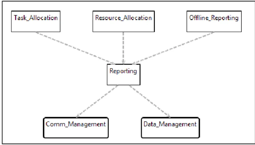
elements. In Figure 4.8, an example textual uses view is given for CMS. The modules and subsystems are listed first and then it is specified which modules uses the others. For example, Task Allocation and Resource Allocation modules uses Reporting modules which mean that crime reporting services must be correctly defined and implemented in order those two modules to be implemented.
Figure 4.8. Textual Uses View The corresponding visual view model is also given in Figure 4.9.
Figure 4.9. Visual uses view
Since there are no topological constraints for uses view, we didn’t implement any well-formedness rules for it.
35
4.3.1.3. Generalization Viewpoint
The generalization viewpoint [7] is useful for modeling is-a relation among modules. When an architect wants to support extension and evolution of architectures and individual elements, this viewpoint can be employed. Modules in this viewpoint are defined in such a way that they capture commonalities and variations. When modules have a generalization relationship, the parent module owns the commonalities, and the children modules own the variations
We have defined DSL for generalization viewpoint. The abstract syntax, grammar and textual and visual examples are given below.
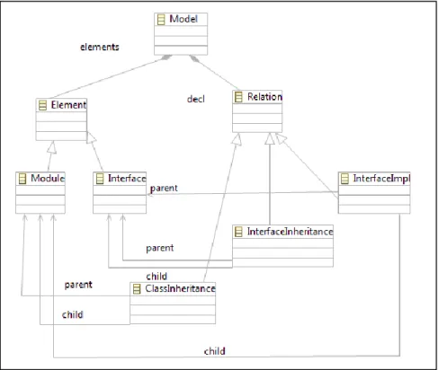
The root node of the grammar is GeneralizationModel. It consists of Elements and Generalization Declarations. An element is either a Module or an Interface. They are identified by their names. Generalization declarations consist of Relations. There are 3 types of relations: InterfaceImpl, ClassInheritance, InterfaceInheritance. If a module contains the implementation of an interface, it is denoted by InterfaceImpl relation. If a module inherits some behavior of other module, it is denoted by ClassInheritance relation. InterfaceInheritance denotes the definition of a new interface based on another previously defined interface. Figure 4.10 gives abstract syntax definition for generalization viewpoint.
36
Figure 4.10. Abstract syntax for generalization viewpoint
In V&B generalization style, only module is defined as element type. If a module is an interface, it is denoted by “abstract” property of the module. Instead of differentiating modules and interfaces with a property, we defined Interface as a first-class abstraction in our grammar. V&B defines generalization relation as relation type and again motivates to differentiate different types of generalizations with properties. In our grammar, we explicitly define 3 types of relations InterfaceImpl, ClassInheritance, InterfaceInheritance. Figure 4.11 shows grammar for generalization viewpoint.
37
Figure 4.11. Grammar for generalization viewpoint
Below is an example generalization view from Crisis Management System. There is a generic module, namely interface, Crisis Handler, which includes the common properties that a specific type of crisis handler class must implement. After defining interfaces and modules the generalization relations are declared. For example, in our case, Car Crash Handler class implements Crisis Handler interface. The corresponding visual generalization view is also shown in Figure 4.13. The visual concrete syntax is very easy to understand. Modules and interfaces are differentiated from each other via their shapes and the Interface Implementation relation is denoted via an empty closed arrow.