multilevel, multiconductor planar transmission lines using MPIE and complex images, 1998 Asia-Pacific Microwave Conference Proceed-ings (Yokohama, Japan), December 8 –11, 1998, Vol. 2, pp. 417– 420. 15. J. Bernal, F. Medina, R.R. Boix, and M. Horno, Fast full wave analysis of multistrip transmission lines based on MPIE and complex images, IEEE Trans Microwave Theory Tech MTT-48 (2000), 445– 452. 16. E.A. Soliman, P. Pieters, E. Beyne, and G.A.E. Vandenbosch,
Numer-ically efficient spatial-domain moment method for multislot transmis-sion lines in layered media. Application to multislot lines in MCM-D technology, IEEE Trans Microwave Theory Tech MTT-47 (1999), 1782–1787.
17. K.A. Michalski and D. Zheng, Electromagnetic scattering and radia-tion by surfaces of arbitrary shape in layered media. Part I: theory, IEEE Trans Antennas Propagat AP-38 (1990), 335–344.
18. F. Mesa and M. Horno, Computation of proper and improper modes in multilayered bianisotropic waveguides, IEEE Trans Microwave The-ory Tech MTT-43 (1995), 233–235.
19. T.K. Sarkar and O. Pereira, Using the matrix pencil method to estimate the parameters of a sum of complex exponentials, Antennas Propagat Mag 37 (1995), 48 –55.
20. M.D. Wu, S.M. Deng, R.B. Wu, and P. Hsu, Full-wave characteriza-tion of the mode conversion in a coplanar waveguide right-angled bend, IEEE Trans Microwave Theory Tech MTT-43 (1995), 2532– 2538.
© 2002 Wiley Periodicals, Inc.
APPLICATIONS OF HYBRID DISCRETE
FOURIER TRANSFORM–MOMENT
METHOD TO THE FAST ANALYSIS OF
LARGE RECTANGULAR DIPOLE
ARRAYS PRINTED ON A THIN
GROUNDED DIELECTRIC SUBSTRATE
Hsi-Tseng Chou,1Hsien-Kwei Ho,2O. A. Civi,3andVakur B. Erturk4
1Department of Electrical Engineering
Yuan Ze University Chung-Li 320, Taiwan
2Graduate Institute of Communication Engineering
National Taiwan University Taipei 106, Taiwan
3Department of Electrical Engineering
Middle East Technical University Ankara, Turkey
4Department of Electrical & Electronics Engineering
Bilkent University Ankara, Turkey
Received 11 January 2002
ABSTRACT: Recently a discrete Fourier transform–method of mo-ments (DFT-MoM) scheme was developed for fast analysis of electri-cally large rectangular planar dipole arrays, which has been shown to be very efficient in terms of number reduction of unknown variables and computational complexity. The applications of this DFT-MoM to treat dipole arrays printed on a grounded dielectric substrate are examined in this Letter. Numerical results are presented to validate its efficiency and accuracy. © 2002 Wiley Periodicals, Inc. Microwave Opt Technol Lett 34: 203–207, 2002; Published online in Wiley InterScience (www. interscience.wiley.com). DOI 10.1002/mop.10417
Key words: discrete Fourier transform; moment method; printed dipole arrays; and dielectric substrate
1. INTRODUCTION
Efficient but accurate analysis of electromagnetic (EM) radiation and scattering from large periodic array remains challenging due to the increasing need to employ very large arrays in the practical applications. A recent work based on a hybrid combination of discrete Fourier transform (DFT) and the conventional method-of-moments (MoM) approach (called DFT-MoM hereafter) [1] was developed to treat the analysis of electrically large, rectangular planar dipole arrays located in free space. Based on the framework of the MoM procedure [2], the DFT-MoM employs a DFT repre-sentation [3] for the unknowns in the rigorous MoM approach. Instead of obtaining the unknowns directly from original MoM matrix equation, the DFT-MoM employs the coefficients of the DFT representation as new unknowns and solves for the DFT coefficients. The MoM unknowns are then obtained subsequently. Several unique advantages have been demonstrated in [1]. First of all, only a few DFT terms are sufficient to represent the MoM unknowns. For a planar and rectangular array (2N ⫹ 2M ⫹ 5) DFT terms are sufficient in contrast to (2N ⫹ 1) ⫻ (2M ⫹ 1) unknowns in conventional MoM approach where (2N ⫹ 1) ⫻ (2M⫹ 1) elements are considered. It is noted that a similar effort based on hybrid uniform geometrical theory of diffraction (UTD) and MoM [4, 5] has also been developed in order to reduce the number of unknowns in the MoM approach. However, in compar-ison with UTD-MoM, the proposed DFT-MoM is more simple and robust in implementation, and is able to fully utilize the advantages of asymptotic techniques [6].
Second, the selected DFT terms accurately represent the un-knowns of conventional MoM because they are selected to suffi-ciently represent the Floquet modes, edge effects of Floquet modes due to finite truncation, and part of the corner effects as interpreted in the UTD-type decompositions on the field propagation [4, 5, 7–9]. Third, each DFT term represents a linearly phased impres-sion on the entire array. The asymptotic techniques [4 –9] can be employed to quickly evaluate the mutual impedance between basis functions of DFT terms, which represent the mutual impedance in terms of a few ray-type contributions instead of element-by-ele-ment computation for the entire array. Furthermore, once the coefficients of DFT terms are obtained via the MoM procedure, the near- and far-field radiations due to each DFT term, which is again a linear phased impression, can be efficiently found via asymptotic techniques [4 –9] that result in the regular array factors for the far-field pattern. It is noted that the asymptotic evaluation of field radiation will give rise to ray-type solutions [7–9] that can be incorporated into existing ray-tracing codes to account for envi-ronmental effects when the arrays are employed in practical ap-plications. Because only a small number of terms are required in this DFT-MoM approach, the efficiency can be readily expected. The applications of this DFT-MoM approach to treat the rect-angular finite planar dipole array printed on a thin grounded dielectric substrate are examined in this Letter. It is noted that in this case the surface and leaky waves due to the presence of the grounded dielectric substrate exist, and potentially increase the computational complexity in the numerical modeling [5]. In this DFT-MoM, which utilizes the full advantages of asymptotic ray-type solutions, not only does the number of DFT terms required to represent the MoM unknowns remain the same, but also the computational complexity increases insignificantly, because only a few additional rays [5, 9] due to surface and leaky waves need to be considered.
This Letter is formatted in the following order. Section 2 will briefly describe the formulation of the DFT-MoM modeling on the simple dipole array printed on a thin grounded dielectric substrate.
This approach can, however, be extended to treat other array types, such as slot arrays and patch arrays, in a similar fashion. Numer-ical validation will be presented in Section 3 to demonstrate its efficiency and accuracy. Finally, a short conclusion will be dis-cussed in Section 4. A time convention of ejt
is assumed and suppressed throughout this Letter.
2. IMPLEMENTATION OF DFT-MOM APPROACH
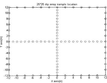
Consider a rectangular finite planar periodic array of printed di-poles oriented in the xˆ direction on a thin grounded dielectric substrate as illustrated in Figure 1 where (2N⫹ 1) ⫻ (2M ⫹ 1) dipoles are indicated. The electric field generated by the currents on dipole array can be expressed as [5]
E共r兲 ⫽ ⫺j
冘
n⫽⫺N N冘
m⫽⫺M M冕
Tnm Gញ 共r/r⬘nm兲 䡠 Inm共x⬘兲xˆ dx⬘, (1)where Gញ (r/r⬘nm) is the electric dyadic Green’s function [10] for an
electric type on a grounded dielectric slab, r and r⬘nm denote the
position vectors for the field point and for any point on the nmth dipole element, and Inm( x⬘) denotes the current distribution on
nmth dipole. For a simple thin-wire half-wavelength dipole array, sinusoidal functions are sufficient, that is, the current distribution
on the nmth (⫺N ⱕ n ⱕ N, ⫺M ⱕ m ⱕ M) dipole can be
described by [11]
Inm共 x⬘兲 ⬵ Anm
sin关ke共h ⫺ 兩x⬘ ⫺ n dx兩兲兴
W sin keh
, (2)
where Anmis the unknown coefficient that determines the current
distribution on the element. h, ke(ke⫽ k0公(r⫹ 1)/ 2) are the
half length and wave number of the expansion mode, respectively, and W is the width of the dipole. Incorporating the Galerkin’s method results in a set of linear equations for the dipole array that can be denoted by
冘
n⫽⫺N N冘
m⫽⫺M M AnmZnm,pq⫽ Vpqe⫺jx pdxe⫺jyqdy, (3)where the right-hand side is the excitation at pqth dipole to radiate a direction beam according to (x, y) defined by
x⫽ sin icosi,
y⫽ sin isini, (4)
with  and (i, i) being the wave number and direction of
scanning beam. It is noted that for a scattering problem, the right-hand side of (3) is associated with the incident field, Ei(rpq),
by
yˆ䡠 Ei共rpq兲 ⫽ Vpqe⫺jx p dx
e⫺jyq d y␦共y ⫺ q dy兲.
(5) The proposed approach employs DFT representation for the unknown coefficients Anm in (3) by Anm⫽ e⫺jx n dx e⫺jym d y
冘
k⫽⫺N N冘
ᐉ⫽⫺M M Bkᐉ ⫻ exp冉
⫺j22Nkn⫹ 1冊
exp冉
⫺j2 ᐉm 2M⫹ 1冊
(6) and results in冘
k⫽⫺N N冘
ᐉ⫽⫺M M BkᐉZ⬘kᐉ,pq⫽ Vpqe⫺jx pdxe⫺jyqdy, (7) where Z⬘kᐉ,pq⫽冘
n⫽⫺N N冘
m⫽⫺M M Znm,pqexp共⫺jxndx兲 ⫻ exp共⫺jymdy兲 exp冉
⫺j 2kn 2N⫹ 1冊
exp冉
⫺ j 2ᐉm 2M⫹ 1冊
(8) which denotes the mutual impedance of kᐉth DFT term and pqth dipole. It is noted that the linear phase shift in (6) allows the distribution of Bklmore centralized around (k ⫽ 0, ᐉ ⫽ 0).The advantage of the expression in (6) is that asymptotic techniques can be employed to quickly evaluate (8) in terms of UTD-type ray solutions. Once the coefficients of Bklare obtained
by solving (7), the radiation field of the array impressed by each DFT can be easily found by asymptotic techniques, which again can be expressed in terms of a few rays and in the far zone is simply an array factor. In particular, the overall far-zone field can be expressed as E共r兲 ⫽ Esin gle共r兲 䡠
冘
k冘
ᐉ Bkᐉ䡠冋
sin冉
2N⫹ 1 2 x冊
/sin冉
x 2冊册
⫻冋
sin冉
2M⫹ 1 2 y冊
/sin冉
y 2冊册
(9)where Esin gle(r) is the far-field pattern of a dipole located at the origin of the coordinate system and
x⫽共sin cos ⫺ sin icosi兲dx⫺
2k 2N⫹ 1,
y⫽共sin sin ⫺ sin isini兲dy⫺
2ᐉ
2M⫹ 1. (10)
Figure 1 A (2N ⫹ 1) ⫻ (2M ⫹ 1) dipole array printed on a thin grounded dielectric substrate
The efficiency of this DFT-MoM is based on a fact that only a relatively few DFT terms are sufficient to represent the induced current on the array. The criterion to determine the significant DFT terms is based on the UTD-type ray interpretation, which intends to include the significant distributions due to Floquet modes and edge-diffracted Floquet modes [1]. In particular, for an uniform excitation [Vpq⫽ 1 in (7)],
冘
ᐉ⫽⫺M M
Bkᐉexp
冉
⫺j22Mᐉm⫹ 1冊
with k⫽ 0 and冘
k⫽⫺N N Bkᐉexp冉
⫺j2 kn 2N⫹ 1冊
with ᐉ ⫽ 0 (11)can sufficiently represent the contributions from the edge-excited Floquet modes. It is noted that edge-excited surface waves [9] are
also sufficiently covered in (11) as well as part of the corner excited field contributions if the substrate is sufficiently thin, as employed in most realistic applications. Furthermore, the signifi-cant contributions of corner diffraction are in general more cen-tralized around (k ⫽ 0, ᐉ ⫽ 0). One may add more terms if exceptional accuracy is desired. However, numerical experiments found that the DFT terms indicated in Figure 2 are sufficient, which requires only (2N ⫹ 2M ⫹ 5) DFT terms for a (2N ⫹ 1) ⫻ (2M ⫹ 1) rectangular array. It is noted that approaches based on minimum least-square error (MLSE) can be employed to find the coefficients of Bklin (7).
3. NUMERICAL RESULTS
Numerical examples are presented in this section to demonstrate the accuracy and efficiency of this DFT-MoM in the analysis of printed dipole arrays on a grounded dielectric substrate. The array considered consists of 25⫻ 25 xˆ-directed dipole elements that are phased to radiate a beam maximum in the direction of ( ⫽ 10°, ⫽ 45°). The array, which is printed on a grounded dielectric substrate with thickness of 0.3 cm and relative dielectric constant of 2.55, has elements in periods of 0.5 and 0.5 in x and y coordinates with sizes of 0.39 and 0.01, respectively, and is excited uniformly in amplitude so that Vpq⫽ 1 in (3) for each of
pqth dipole. The operating frequency is 3 GHz. The results
pre-Figure 2 Selected DFT terms to represent the induced currents on the array for the DFT-MoM computation and the corresponding selected dipoles for the implementation of MLSE computation to find the coeffi-cients of DFT terms
Figure 3 Induced current distribution on the array (only the magnitudes and phases of Anmare plotted). (a) Shows the distribution on the bottom
row of the array and (b) shows the distribution on the central row of the array
sented are compared with reference solutions that are obtained from rigorous MoM analysis.
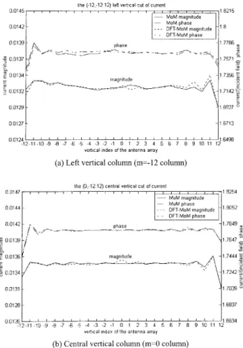
Figure 3 shows the normalized induced current envelope [i.e., the coefficients of Anmin (2)] on the dipole array for the bottom
and central horizontal rows (n⫽ ⫺12 and 0) in terms of magni-tude and phase variation. The accuracy can be observed from the fact that the results obtained from DFT-MoM have excellent agreement with the reference results obtained from rigorous MoM, except minor errors can be found on the first two and last two elements (m⫽ ⫺12, ⫺11, 11, and 12) in the first column (n ⫽ ⫺12) shown in Figure 3(a), which correspond to the corner elements. Similar accuracy can be also observed from Figure 4, which shows that normalized induced current envelope for the left and central vertical columns (m⫽ ⫺12 and 0). The minor errors are expected, because the selected DFT terms in (6) intend to potentially represent Floquet modes, the entire contribution due to the edge truncation, and a part of the corner contribution. How-ever, as mentioned in an earlier section the corner effects have insignificant contribution on the entire array except on the small areas of corner elements, and usually can be ignored in the regions that are at least one wavelength away from the corner. One may impose unknown variables on the corner elements in the DFT-MOM approach if an exceptional accuracy on the corner elements is required. It will, however, not increase the unknown number significantly, because the sizes of the corner areas are, in general, fixed and independent of the array size. Furthermore, with increas-ing array size the overall ratio of the corner error on the entire array
current distribution will decrease significantly. It is noted that only 53 DFT terms, instead of 625 unknowns in MoM, are employed (which is less than 9%). Extensive numerical experiments, as also indicated in Figure 5, have shown that the overall percentage errors on the entire induced current, which are defined by
Figure 6 Radiation pattern of a 25⫻ 25 printed dipole array (they are normalized under the same conditions)
Figure 4 Induced current distribution on the array (only the magnitudes and phases of Anm are plotted). (a) Shows the distribution on the left
column (m⫽ ⫺12 column) of the array and (b) shows the distribution on the central column (m⫽ 0 column) of the array
Figure 5 Percentage error of the DFT-MoM solution in comparison with the rigorous MoM solution. The array is assumed to have dimensions of N⫻ N
Percentage⫺ error ⫽储IMoM⫺ IDFT-MoM储 储IMoM储
, (12)
are less than 1.5% and generally decrease, while the array size increases, where I⬅ [Anm] and the subscripts indicate the
coef-ficients obtained from MoM and DFT-MoM, respectively. Numer-ical experience has shown that the error will slightly increase as the thickness of the substrate sufficiently increases, where the surface and leaky waves become dominant. However, the errors are generally less than 2% for all of the practical cases that have been examined.
Finally the radiation patterns of Eand Ecomponents for the array example are shown in Figure 6 for comparison with rigorous MoM results. As expected, the agreements on the patterns obtained DFT-MoM and conventional MoM are excellent, and no differ-ence can be distinguished. The distribution of Bkᐉ is shown in
Figure 7 to validate the criterion in selecting significant DFT terms suggested in (11).
4. CONCLUSION
In this Letter the applications of the DFT-MoM approach to the fast analysis of EM radiation/scattering from a large rectangular planar dipole arrays printed on a thin grounded dielectric substrate are examined. The DFT-MoM employs DFT representation to describe the induced current on the array, which allows the ad-vantages of asymptotic ray solutions to be fully utilized. Because only a relatively few DFT terms are required, the efficiency of this DFT-MoM is extremely high.
REFERENCES
1. H.T. Chou, H.K. Ho, P.H. Pathak, P. Nepa, and O.A. Civi, An efficient approach based on discrete Fourier transform–moment method for the fast analysis of large rectangular array, IEE Proc Microwaves Anten-nas Propagat.
2. R. Harrington, Field computation by moment methods, IEEE Press Series on Electromagnetic Waves, Oxford University Press, Piscat-away, NJ, 1993.
3. A.V. Oppenheim and R.W. Schafer, Discrete-time signal processing, Prentice Hall, Upper Saddle River, NJ, 1999.
4. O.A. Civi, P.H. Pathak, H.T. Chou, and P. Nepa, A hybrid uniform geometrical theory of diffraction–moment method for the efficient analysis of electromagnetic radiation/scattering from large finite planar arrays, Radio Sci 35 (2000), 607– 620.
5. O.A. Civi, V.B. Erturk, P.H. Pathak, P. Janpugdee, and H.T. Chou, A
hybrid UTD-MoM approach for the efficient analysis of radiation/ scattering from large, printed finite phased arrays, APS International Symposium and URSI Radio Science National Meeting, Boston, July 2001.
6. L.B. Felson and N. Marcuvitz, Radiation and scattering of waves, Prentice-Hall, Englewood Cliffs, NJ, 1973, Chap. 4.
7. F. Capolino, M. Albani, S. Maci, and L.B. Felsen, Floquet wave diffraction theory for truncated dipole arrays: Propagating and evanes-cent spectra, paper presented at URSI EMT meeting in Thessaloniki, Greece, May, 1998.
8. A. Neto, S. Maci, G. Vecchi, and M. Sabbadini, A truncated Floquet wave diffraction method for the full-wave analysis of large phased arrays. Part 2: Generalization to 3D cases. IEEE Trans Antennas Propagat AP-48 (2000), 601– 611.
9. P. Janpugdee, P. Pathak, N. Nepa, O. Civi, and H.T. Chou, Ray analysis of radiation from a large finite phased array of antennas on a ground material slab, paper presented in IEEE AP-S Intal Symposium, Boston, July 2001.
10. C.T. Tai, Dyadic Green functions in electromagnetic theory (2nd ed.), IEEE Press series on Electromagnetic Waves, Piscataway, NJ, 1994. 11. D.M. Pozar, Analysis of finite phase arrays of printed dipoles, IEEE
Trans Antennas Propagat AP-33 (1985), 1045–1053. © 2002 Wiley Periodicals, Inc.
SUPERPOSITION OF THE OUTPUT
PULSES UNDER SYNCHRONOUS
DISCHARGE IN A
MULTIPLE-ELECTRODE-PAIR LASER
Lihua Ye,1Tao Sha,2Xiangyin Li,3Anzhi He,3and Yiping Cui1
1Department of Electronic Engineering
Southeast University Nanjing 210096, P. R. China
2Automation Department
Nanjing University of Science and Technology Nanjing 210094, P. R. China
3Department of Applied Physics
Nanjing University of Science and Technology Nanjing 210094, P. R. China
Received 16 January 2002
ABSTRACT: If the pressure, voltage, and other discharge parame-ters of a multiple-electrode-pair laser are held constant, there is a non-linear pulse energy enhancement effect when several sets of electrode pairs are triggered synchronously. The mechanism of the effect is ana-lyzed and a reasonable theoretical model, which is in agreement with the experimental results, is built. © 2002 Wiley Periodicals, Inc. Microwave Opt Technol Lett 34: 207–211, 2002; Published online in Wiley InterScience (www.interscience.wiley.com). DOI 10.1002/mop. 10418
Key words: pulse energy enhancement; multiple-electrode-pair laser; gas laser
1. INTRODUCTION
By using several sets of electrode pairs sharing the same optical cavity and firing each electrode-pair set sequentially, a series of laser pulses with an adjustable time interval can be generated [1– 4]. There are many applications for this high-intensity short-time-interval laser pulse series, such as laser remote sensing, holography, biology, photochemistry, optical diagnostics, laser fusion, and so on [5–9]. The multiple-electrode-pair laser has unique output characteristics. For example, the pulse energy output is sensitive to the trigger time interval. When the pulse discharge
Figure 7 Distributions of Bkᐉto demonstrate the validity of criterion in