Multiple slow waves and relevant transverse
transmission and confinement in chirped
photonic crystals
Andriy E. Serebryannikov,1,2,3,* A. Ozgur Cakmak,4 Evrim Colak,5 Humeyra Caglayan,1,6 Hamza Kurt,7 and Ekmel Ozbay1 1Nanotechnology Research Center-NANOTAM, Bilkent University, 06800 Ankara, Turkey
2Hamburg University of Technology, E-3, D-21071 Hamburg, Germany 3Faculty of Physics, Adam Mickiewicz University, 61-614 Poznan, Poland
4Center for Nanotechnology Education and Utilization, The Pennsylvania State University, University Park, Pennsylvania 16802, USA
5Department of Electrical and Electronics Engineering, Ankara University, Golbasi, 06830 Ankara, Turkey 6Department of Electrical and Electronics Engineering, Abdullah Gul University, 38039 Kayseri, Turkey 7Nanophotonics Research Laboratory, Department of Electrical and Electronics Engineering, TOBB University of
Economics and Technology, 06560 Ankara, Turkey *
Abstract: The dispersion properties of rod-type chirped photonic crystals
(PhCs) and non-channeled transmission in the direction of the variation of structural parameters from one cell of such a PhC to another are studied. Two types of configurations that enable multiple slow waves but differ in the utilized chirping scheme are compared. It is demonstrated that the multiple, nearly flat bands with a group index of refraction exceeding 180 can be obtained. For these bands, transmission is characterized by multiple narrow peaks of perfect transmission, strong field enhancement inside the slab, and large values of the Q-factor. Among the bands, there are some that show negative phase velocity. Symmetry with respect to the slab mid-plane must be kept in order to obtain constructive interferences that are necessary for reflection-free transmission. It is shown that 15 and more slow wave bands can be obtained in one configuration. The corresponding transmission peaks are well separated from each other, being the only significant feature of the transmission spectrum, while the Q-factor can exceed 105. The observed features are preserved in a wide range of the incidence angle variation. They can be used for tuning the locations and spectral widths of the transmission peaks. Some comparisons with the chirped multilayer structures have been carried out.
©2014 Optical Society of America
OCIS codes: (050.5298) Photonic crystals; (050.1590) Chirping; (050.1940) Diffraction; (260.2030) Dispersion; (260.2110) Electromagnetic optics.
References and links
1. A. Figotin and I. Vitebskiy, “Oblique frozen modes in periodic layered media,” Phys. Rev. E Stat. Nonlin. Soft Matter Phys. 68(3), 036609 (2003).
2. T. Baba, “Slow light in photonic crystals,” Nat. Photonics 2(8), 465–473 (2008).
3. J. B. Khurgin, “Optical buffers based on slow light in electromagnetically induced transparent media and coupled resonator structures: comparative analysis,” J. Opt. Soc. Am. B 22(5), 1062–1074 (2005). 4. S. Mookherjea, J. S. Park, S.-H. Yang, and P. R. Bandaru, “Localization in silicon nanophotonic slow-light
waveguides,” Nat. Photonics 2, 90–93 (2008).
5. M. Beruete, P. Rodriguez-Ulibarri, V. Pacheco-Pena, M. Navarro-Cia, and A. E. Serebryannikov, “Frozen mode from hybridized extraordinary transmission and Fabry-Perot resonances,” Phys. Rev. B 87(20), 205128 (2013). 6. T. Baba, D. Mori, K. Inoshita, and Y. Kuroki, “Light localizations in photonic crystal line defect waveguides,”
IEEE J. Sel. Top. Quantum Electron. 10(3), 484–491 (2004).
7. C. Caer, X. Le Roux, and E. Cassan, “Enhanced localization of light in slow wave slot photonic crystal waveguides,” Opt. Lett. 37(17), 3660–3662 (2012).
8. H. Caglayan, I. Bulu, and E. Ozbay, “Highly directional enhanced radiation from sources embedded inside three-dimensional photonic crystals,” Opt. Express 13(19), 7645–7652 (2005).
9. A. Figotin and I. Vitebskiy, “Slow wave phenomena in photonic crystals,” Laser Photon. Rev. 5(2), 201–213 (2011).
10. A. E. Serebryannikov, E. Ozbay, and P. V. Usik, “Defect-mode-like transmission and localization of light in photonic crystals without defects,” Phys. Rev. B 82(16), 165131 (2010).
11. B.-K. Song, S. Noda, T. Asano, and Y. Akahane, “Ultra-high-Q photonic double-heterostructure nanocavity,” Nat. Mater. 4(3), 207–210 (2005).
12. A. Kuramochi, M. Notomi, S. Mitsugi, A. Shinya, T. Tanabe, and T. Watanabe, “Ultra-high-Q photonic crystal nanocavities realized by local width modulation of a line defect,” Appl. Phys. Lett. 88(4), 041112 (2006). 13. J. Topolancik, B. Ilic, and F. Vollmer, “Experimental observation of strong photon localization in disordered
photonic crystal waveguides,” Phys. Rev. Lett. 99(25), 253901 (2007).
14. F. Vollmer and J. Topolancik, “Disorder induced high-Q cavities in photonic crystal waveguides,” Proc. SPIE 6872, 68720X (2008), doi:10.1117/12.773405.
15. J. H. Wu, L. K. Ang, A. Q. Liu, H. G. Teo, and C. Lu, “Tunable high-Q photonic-bandgap Fabry-Perot resonator,” J. Opt. Soc. Am. B 22(8), 1770–1777 (2005).
16. A. E. Serebryannikov and T. Magath, “Transmission through photonic crystals with multiple line defects at oblique incidence,” J. Opt. Soc. Am. B 25(3), 286–296 (2008).
17. H. Kurt, N. Erim, and K. Üstün, “Slow light based on optical surface modes of two-dimensional photonic crystals,” J. Opt. Soc. Am. B 29(6), 1187–1193 (2012).
18. L. Zhu, F.-Y. Meng, J.-H. Fu, Q. Wu, and J. Hua, “Multi-band slow light metamaterial,” Opt. Express 20(4), 4494–4502 (2012).
19. H. Kurt, H. Benisty, T. Melo, O. Khayam, and C. Cambournac, “Slow-light regime and critical coupling in highly multimode corrugated waveguides,” J. Opt. Soc. Am. B 25(12), C1–C14 (2008).
20. J. P. Vigneron and V. Lousse, “Theory of chirped photonic crystals,” Opt. Quantum Electron. 39(4-6), 377–385 (2007).
21. D.-H. Kwon and D. H. Werner, “Transformation optical designs for wave collimators, flat lenses and right-angle bands,” New J. Phys. 10(11), 115023 (2008).
22. E. Akmansoy, E. Centeno, K. Vynck, D. Cassagne, and J.-M. Lourtioz, “Graded photonic crystals curve the flow of light: An experimental demonstration by the mirage effect,” Appl. Phys. Lett. 92(13), 133501 (2008). 23. T. Driscoll, D. N. Basov, A. F. Starr, P. M. Rye, S. Nemat-Nasser, D. Schurig, and D. R. Smith, “Free-space
microwave focusing by a negative-index gradient lens,” Appl. Phys. Lett. 88(8), 081101 (2006). 24. H. Kurt and D. S. Citrin, “Graded index photonic crystals,” Opt. Express 15(3), 1240–1253 (2007). 25. H. Kurt, E. Colak, O. Cakmak, H. Caglayan, and E. Ozbay, “The focusing effect of graded-index photonic
crystal,” Appl. Phys. Lett. 93(17), 171108 (2008).
26. A. O. Cakmak, E. Colak, H. Caglayan, H. Kurt, and E. Ozbay, “High efficiency of graded index photonic crystal as an input coupler,” J. Appl. Phys. 105(10), 103708 (2009).
27. K. Staliunas and V. J. Sánchez-Morcillo, “Spatial filtering of light by chirped photonic crystals,” Phys. Rev. A 79(5), 053807 (2009).
28. D. Mori and T. Baba, “Dispersion controlled optical group delay device by chirping photonic crystal waveguides,” Appl. Phys. Lett. 85(7), 1101–1103 (2004).
29. T. Magath and A. E. Serebryannikov, “Fast iterative, coupled-integral-equation technique for inhomogeneous profiled and periodic slabs,” J. Opt. Soc. Am. A 22(11), 2405–2418 (2005).
30. A. E. Serebryannikov, A. Y. Petrov, and E. Ozbay, “Toward photonic crystal based spatial filters with wide angle ranges of total transmission,” Appl. Phys. Lett. 94(18), 181101 (2009).
31. W. Zhu, D. A. McNamara, and J. Shaker, “Beam switching and scattering analysis for a microwave hologram modeled by disk lattices with transversely modulated sizes,” Microw. Opt. Technol. Lett. 43(5), 390–394 (2004). 32. M. Born and E. Wolf, Priciples of Optics: Electromagnetic Theory of Propagation, Interference and Diffraction
of Light (Pergamon Press, Oxford, 1970), pp. 325–326.
33. W. Zhong and X. Zhang, “Localized modes in defect-free two-dimensional circular photonic crystals,” Phys. Rev. A 81(1), 013805 (2010).
1. Introduction
Electromagnetic waves with a small group velocity and a large group index of refraction are known to appear in various optical and microwave structures [1–5]. The simplest among them represents a high-index homogeneous medium. However, a proper material might be difficult to find especially at optical frequencies. The use of periodic structures such as photonic crystals (PhCs) and metastructures look promising from the point of view of overcoming these difficulties. Different features and manifestations of slow light in one- and two-dimensional PhCs with [2,4,6,7] and without [1,3,8–10] defects have been studied. The interest in slow-wave regimes in these structures has been stimulated by the possible applications, such as buffers for the time-domain processing of optical signals and the compression of optical energy. In particular, group indices ranging from ng 20 to 100 are
typical for defect mode waveguides working near the band edge [2]. Large values of ng can
also be obtained when an electromagnetic wave propagates through a one-dimensional PhC with defects (i.e., in the direction perpendicular to the layers including defect sites), which work as the coupled Fabry-Perot cavities [3]. Other coupled resonator structures, e.g., those based on microring resonators and coupled point defects in two-dimensional PhCs have also been considered in the context of slow light and buffering [3]. Moreover, slow-wave phenomena have been found in some types of one-dimensional PhCs without defects (e.g., frozen modes) [1,9]. Strong field localization is often associated with small group velocity and, thus, with large values of n in defect [4,6] and slot [7] PhC waveguides. At the same g
time, slow waves enable high-Q regimes [11,12]. For instance, the possibility of obtaining
7
10
Q in the nanocavity created in the defect mode waveguide has been demonstrated. Anderson localization and disorder relevant high-Q regimes should be mentioned [13,14] in order to illustrate that slow waves may appear in various structures and physical situations.
Transmission through the slow-wave structures that represent finite slabs of conventional two-dimensional PhCs without defects (ng20) is characterized at an inclined incidence of a plane electromagnetic wave (angle of incidence 0) by multiple peaks of perfect transmission, which are well separated from each other [10]. This type of behavior has also been observed in two-dimensional PhCs with a single wide defect at 0 [15] and multiple narrow defects at an oblique incidence [16]. It enables multiple band tunable filters. The symmetry of a slab with respect to the mid-plane can lead to the constructive Fabry-Perot type interferences and, therefore, to the perfect transmission at the defect mode relevant peaks. In fact, such defect modes are also associated with slow light, because they typically show a quite flat dispersion. On the other hand, strong field enhancement also occurs inside the slabs of defect-free PhCs where Q106 can be achieved [10]. In fact, the connection
between the large values of n , strong field localization, and large Q values is evident, g
regardless of whether the slab contains structural defects or not. Large values of n (e.g., g
20
g
n ) can also be obtained in the slabs of PhC with the properly designed interface layers of the rods [17]. Achieving multiple narrow bands for such a slab usually requires a rather large total thickness. At the same time, attempts to decrease it again lead to the necessity of utilizing high-index materials, which are placed now within defect(s). Thus, an efficient route to compact performances for multiband slow-wave operation is very important for practical purposes. Regarding this, one should mention the recently suggested metamaterials with multiple slow-wave bands [18]. In addition, multiple slow waves have been demonstrated in the PhC defect mode waveguides. Their dispersion shows the oscillatory behavior inside the band, while n can reach several tens [19]. g
PhCs with the structural parameters of the unit cells that varied gradually from one cell to the neighboring ones are known as chirped PhCs [20]. Generally speaking, various chirped structures, which are in some sense intermediate between periodic and disordered ones, have a rich potential in obtaining the desired dispersion, transmission, and scattering properties. For example, the potential of gradual variation of material characteristics in the design of complex photonic structures has recently been demonstrated in the framework of the Transformation Optics approach [21–23]. A large class of the graded-index PhCs has been studied with the emphasis placed on propagation in the direction perpendicular to that of the variation of structural parameters, e.g., for focusing and coupler applications [24–26]. Chirped PhCs have also been proposed for efficient spatial filtering [27]. Chirping walls of the defect mode waveguide in a two-dimensional PhC has been used in a group delay device with group velocities less than c100 [28].
In this paper, we show that a properly designed slab of chirped PhCs can enable an extremely large number of flat bands that are characterized by large n and cause multiple g
performances. The studied chirped PhCs are different than those usually studied, e.g., see [21–26]. In particular, the present PhCs are symmetric with respect to the mid-plane, while the focus here is on propagation in the direction of the variation of structural parameters. At the same time, the suggested PhCs utilize conventional dielectrics and do not require any exotic material properties. Two approaches to chirping will be compared from the multiple slow wave perspective. In one of the approaches, the distance between the rods is varied from one pair of the rods to another, while the rod diameter is changed from one PhC cell to another in the second approach. The resulting configurations may combine the dispersion and transmission properties of a conventional defect-free PhC at lower frequencies with unusual slow-wave properties at higher frequencies. Slow waves with ng 180 at the middle of the band and much larger n at the edges of a narrow, nearly flat band will be demonstrated. g
Such bands may show either positive or negative slope that yields either positive or negative refraction. It will be shown that Q105 can be obtained, whereas the locations of the
transmission peaks can be tuned by varying θ. The possible effects of diffraction will also be considered. Non-channeled transmission is studied here in the plane-wave framework that provides some flexibility for the actual input and exit beams. Moreover, the non-oscillatory behavior of an entire slow-wave band and multiple peaks of perfect transmission, which are well separated from each other, are typical for the suggested structures. To calculate the band and dispersion diagrams, Plane Wave Expansion Method has been utilized. Transmission has been calculated by using an integral equation technique [29].
2. Geometry, dispersion, and nearly flat bands
The general geometry of finite-thickness chirped PhCs of two types, which are studied in this paper, is shown in Fig. 1. They are composed of dielectric rods that are assumed to be infinitely long. The resulting structures have a finite thickness in the y-direction but are infinitely extended and periodic in the x-direction. Thus, they may be considered as gratings. However, although the regimes with the propagating higher diffraction orders will also be considered in this paper, our main interest is related to the transmission regimes that are free of diffractions. A structure is assumed to be illuminated by the s-polarized plane wave with an electric field vector that is parallel to the rod axes, so that the normal incidence ( 0) is along the y axis (transverse transmission). In order to better connect to our previous work and explain the chirped PhC composition, we first took a slab of the uniform, i.e., defect-free, square-lattice dielectric PhC with the rod-diameter-to-lattice-constant ratio d a0.4 and number of the rod layers N11, see [10,30]. It is referred to as the benchmark PhC.
To obtain configuration A, as shown in Fig. 1(a), we placed the rods at (0)
i i i
y y C a, where (0) 2 ( 1)
i
y a i a are locations of the rods in the benchmark PhC, while i takes the values from 1 to 11; Ci are the coefficients that set the shifts of the rods as compared to the
benchmark PhC; C1C6C110, C2 C100.6, C3 C90.625, C4 C80.55, and C5 C70.4. Thus, the rod layers located in the middle (i6) and at the interfaces (i1,11) remain at the same places as in the benchmark PhC. For configuration B, as shown in Fig. 1(b), we changed the diameters of the rods, while the distance between the centers of the neighboring rods has been kept the same as in the benchmark PhC. We took diG di , where d is the diameter of the rods in the benchmark PhC, G1G110.8, G2G100.96,
3 9 1.12
G G , G4G81.28, G5G71.44, and G61.6. High-efficiency transmission arises due to the multiple reflections inside the slab of the chirped PhC. On the other hand, complete reflection or suppression of transmission peaks is due to destructive interference from each cell that has a different dielectric filling factor. In our study, the value of a typically does not exceed one free-space wavelength. The rods are assumed to be made of lossless dielectrics, so that dimensionless variables are used.
Fig. 1. Geometry of the configurations A (a) and B (b), within several lateral (grating) periods.
Fig. 2. Band diagram for the superlattice that corresponds to (a) configuration A and (b) configuration B at r 9.61; blue – conventional low-frequency bands, red – nearly flat bands, green – conventional high-frequency bands; increased fragments of the band diagram are shown on the right panel.
Note that configuration A is similar to those studied in [24–26], but in contrast to them, propagation in the direction of variation of structural parameters from one cell of PhC to another will be studied here. In turn, configuration B, which was studied in this work, somehow resembles the disk grating in [31]. However, materials (dielectric vs. metallic), geometry of individual components (rods vs. disks) and ultimate goals (slow light vs. beam switching) are totally different. It is noteworthy that the slab in [31] has been obtained by taking finite thickness in the direction perpendicular to that of structural parameters variation. This results, in particular, in that higher diffraction orders begin to contribute at substantially smaller frequencies.
Fig. 3. Phase (a,c,e) and group (b,d,f) index of refraction for three selected bands in configuration A at r9.61; blue lines - vph0, red lines - vph0.
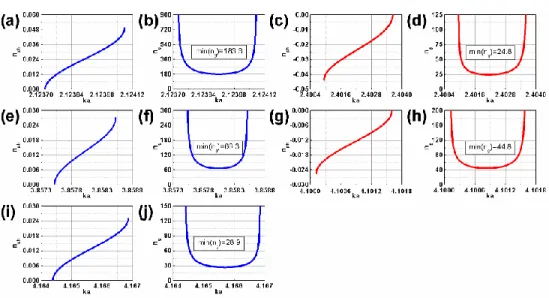
Fig. 4. Phase (a,c,e,g,i) and group (b,d,f,h,j) index of refraction for selected bands in configuration B at r 9.61; blue lines - vph0, red lines - vph0.
Next, dispersion has been calculated by using the supercell approach and the plane-wave expansion technique. The band diagrams for configurations A and B are presented in Fig. 2 when the rod permittivity is r 9.61, which corresponds to Al2O3. Three typical ka-ranges
(k c is free-space wavenumber) can be distinguished in Figs. 2(a) and 2(b). At small ka, there is no flat band, while the band slope varies slightly. For the intermediate values of ka,
values of n . These bands look similar to those corresponding to the defect modes arising in g
the conventional uniform PhCs, say, with a square lattice and a single wide defect or multiple narrow defects [15,16]. However, for ka3 the observed bands again show a significant slope for configuration A, but are still flat for configuration B. As a result, an unusually large number of the slow waves can be obtained in the latter case. If one only needs two or three such bands, either PhCs with defects like those in [15,16] or configurations A and B at ka3
can be utilized.
Phase and group indices of refraction, nph and n for the selected nearly flat bands from g
Fig. 2(a) are presented in Fig. 3. The bands are chosen that are characterized by large values of minn , which correspond to the band middle. Large values of g n can be obtained for both g
cases of parallel and antiparallel phase and group velocities. In particular, minng38.5 for the positive slope (positive phase velocity) band located at ka2 and minng16.3 for the negative slope (negative phase velocity) band located near ka3. In turn, Fig. 4 presents the results for nph and n for the selected bands taken from Fig. 2(b). Here, ming ng183 for the positive slope band near ka2.12 and minng24.7 for the negative slope band near
2.4
ka . Moreover, there are other bands with minng40, see Figs. 4(f) and 4(h). One can see that configuration B enables not only a larger number of the nearly flat bands, but also larger values of minn for these bands. However, the dispersion results themselves do not g
give an idea of which of these modes can be efficiently coupled, say, at normal incidence. Thus, the transmission results are required.
3. Transverse transmission
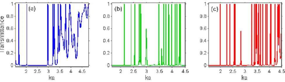
In this section, we demonstrate the typical features of transmission that are connected with multiple flat bands. The range of ka variation is chosen so that it includes the bands shown in red lines in Fig. 2. An example of transmittance (T) vs. ka is shown in Fig. 5. The multiple peaks of T1 are observed. They correspond to perfect (reflection-free) transmission and, as desired, are well separated from each other. It is noteworthy that there are no other bands except for the flat ones in the ka-range, where flat bands are located. Hence, the connection between slow waves and multiple peaks of T is evident.
Fig. 5. Transmittance for (a) configuration A at r9.61, (b) configuration B at r 9.61, and (c) configuration B at r 11.4, in a wide range of ka variation, 0.
Accordingly, multiple stop bands appear between the peaks in Fig. 5. The alternating peaks and stop bands observed for configuration A in Fig. 5(a) are similar to those in the uniform PhCs with either several narrow line defects [16] or a single wide line defect [15], which are parallel to the interfaces. A comparison with the dispersion results also supports this analogy, because the dispersion of defect modes for the considered propagation direction is also nearly flat in these structures, too. However, the number of the peaks in our case can be substantially larger. Note that the ka-range, where narrow perfect-transmission peaks are observed in Fig. 5(a), coincides well with the lowest stop band of the benchmark uniform PhC (not shown), in which defect mode relevant peaks can appear if defects are properly
introduced. Moreover, for ka1.5 and ka3.4 transmittance behavior for configuration A in Fig. 5(a) is similar to that of a uniform defect-free PhC with multiple wide bands. The mentioned ka-ranges correspond to the bands shown in blue and green lines in Fig. 2(a).
Transmittance for configuration B in Fig. 5(b) is similar to that of the corresponding uniform PhC only at ka1.5, see the bands shown in blue lines in Fig. 2(b). At larger ka, narrow peaks dominate over other transmission features, see the bands shown in red lines in Fig. 2(b). In fact, transmittance in Figs. 5(b) and 5(c) might appear for a finite-thickness slab of hypothetic uniform PhC with an extremely wide stop band and a very wide, centered line defect. In the considered structures, this type of behavior does not need a wide line defect. On the other hand, the observed transmission features could appear in homogeneous slabs of a dielectric material with exotic properties. In our case, conventional dielectric materials are only required, see Fig. 1, Eq. (3) and discussion in [10]. The detected differences between configurations A and B remain in wide ranges of the variation in d a and r. The obtained results show that the chirping based on the variation of the rod diameter might be preferable when multiple slow waves and related narrow peaks of perfect transmission are desirable. In Fig. 5(a), one can only see three consequent peaks of T1, which are well separated from each other. Indeed, in Fig. 5(b), we have three peaks for 2ka2.6 and one twinned peak at
2.75
ka . Then, a single narrow peak appears near ka3.5, and six subsequent peaks appear at 3.6ka4.2. Finally, the twinned peak is seen near ka4.3. Thus, there are 10 sole peaks plus the twinned peaks. In the case shown in Fig. 5(c), the total number of the well separated peaks at 1.9ka4.4 is 15. Hence, multiple narrow bands can be obtained in one configuration that can be useful for filtering and sensing applications. The features observed in Fig. 5 are rather general. For example, they remain for a wide range of d a variation. The same remains true regarding configuration B in Figs. 5(b) and 5(c): for several alternative choices of the values of Gi, the same transmission features have been observed. For validation purposes, the transmission results that were obtained using the integral equation technique [29] and a FDTD technique have been compared. They are in good agreement.
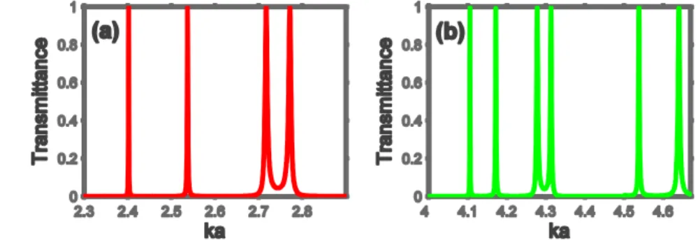
Fig. 6. Transmittance for configuration B at r 9.61 and 0, in two ranges of ka variation, where multiple narrow peaks are located, in the vicinity of (a) ka2.6 and (b)
4.3
ka .
Attempts to obtain multiple and well separated peaks of T1 in slabs of chirped PhCs with a smaller thickness than in Fig. 1 have not yet been successful. For example, taking
5
N or N7, i.e., removing some layers of the rods from the near-interface subregions of the original configurations in Fig. 1, for which N11, did not yield multiple peaks being well separated from their neighbors. Variations in Gi or Ci did not result in significant improvements.
In order to better illustrate the most typical features of transmission, Fig. 6 presents two fragments of the dependence of T on ka for configuration B from Fig. 5(b). The same
behavior is observed within both subranges of ka variation. They are located rather far from each other but still can be assigned to the same wide ka-range, for which multiple narrow peaks of T1 represent the main feature of transmission. Compared to the defect-mode like narrow transmission peaks studied in [10] for the slab of a square-lattice dielectric PhC at intermediate θ, the peaks of T1 in Fig. 6 look similar but may occupy a much wider spectral range. Furthermore, they are obtained here at 0. In contrast to [10], where all of the narrow peaks are connected with the same Floquet-Bloch mode, multiple peaks of T in Figs. 5 and 6 correspond to multiple modes with a nearly flat dispersion.
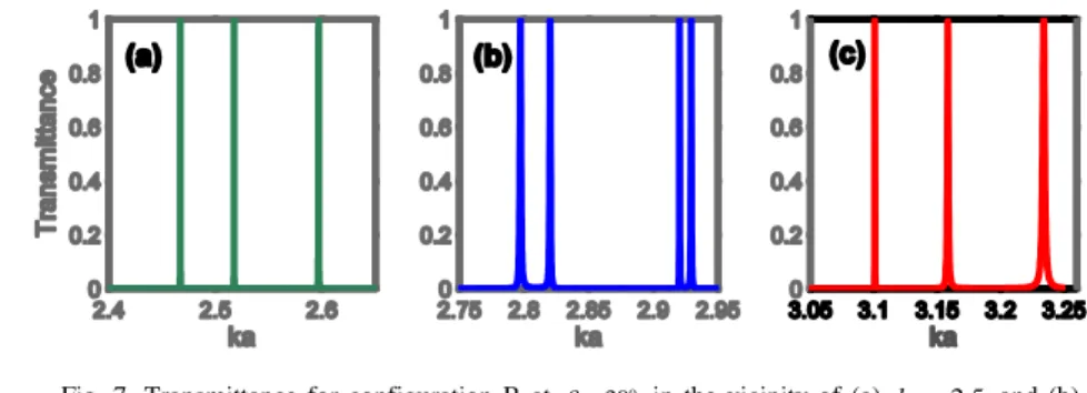
Fig. 7. Transmittance for configuration B at 30o in the vicinity of (a) ka2.5 and (b) 2.85
ka , and (c) for configuration A at 45o near ka3.15; 9.61 r
; note that the ranges used in plots (a) and (b) partially coincide with those in Figs. 5(b) and 6(a), the ka-range in plot (c) partially coincides with that in Fig. 5(a).
The above-mentioned analogy between the chirped PhCs and the uniform PhCs with defects remains for 0. Taking a value of 0 may lead to some spectral modifications but not to new features compared to the case of 0. Multiple narrow peaks can be tuned by varying θ, similar to [10,15,16]. It is noteworthy that the number of the separated peaks within a fixed ka range can depend on θ. This may happen due to the improvement of separation between the maxima of the twinned peaks observed at 0 or the coupling of the modes that have been uncoupled at 0. Figure 7 presents three examples of several subsequent peaks of T1 at 0, for the same configurations and parameter settings as in Figs. 5 and 6. The effects of continuous variation in θ have not been studied here. However, the dependencies of T on ka obtained at different values of θ are sufficient to demonstrate the possibility of tuning by switching between two values, 1 and 2, at which the locations of the multiple peaks of T1 are different. Compared to [19], the non-oscillatory behavior of an entire slow-wave band and multiple peaks of perfect transmission, which are well separated from each other, are typical features of the suggested structures.
4. Field confinement and high-Q regimes
High-Q modes in PhC based structures are often associated with strong field confinement in defect-mode waveguides. If a slow wave appears due to a nearly flat narrow band, as in Fig. 2, field confinement may appear in the entire slab of PhC. In other words, the field can be strongly enhanced compared to the surrounding low-index host medium. In fact, band flatness corresponds to the large values of n and forces the transmission to be narrowband, at least if g
the band is well separated from its neighbors. In turn, narrow transmission peaks are associated with high-Q regimes. On the other hand, the large values of Q generally indicate strong field enhancement within certain regions that are connected with wave slowness. This is true for the structures with and without defects. Some details of the above-mentioned connections between different characteristics have been studied for various PhC based structures, e.g., see [4,6,7,10–12,15]. In this section, we investigate which confinement
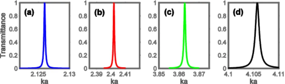
scenarios and values of Q-factor are typical for configurations A and B. Figure 8 presents T vs. ka near the four selected peaks of T1 for configuration B with the same parameters as in Figs. 5(b) and 6. In Figs. 8(a), 8(b), 8(c), and 8(d), Q-factor is equal to 8.5 10 3, 1.3 10 3,
3
4.15 10 , and 4.5 10 3, respectively. In all of these cases, the peaks are well separated from
their neighbors (not shown), which appear due to similar but not the same modes.
Fig. 8. Transmittance for configuration B at r9.61 and 0 in vicinity of (a) ka2.125, (b) ka2.4, (c) ka3.86, and (d) ka4.105.
One can obtain larger values of Q-factor than in Fig. 8, by adjusting the PhC parameters and/or θ value. Furthermore, this can also be done for the smaller values of r than in Fig. 8.
T as a function of ka is presented in Fig. 9 for three selected cases, at the same geometrical
parameters of the slab of PhC as in Fig. 6 but at the different values of either r or θ. Q-factor is equal to 3.1 10 4, 2.6 10 4, and 7.6 10 4 in plots (a), (b), and (c), respectively. Hence,
4
10
Q can easily be obtained in the studied configurations, for both normal and inclined incidence.
Fig. 9. Transmittance for configuration B at r5.8 and 0 in vicinity of (a) 4.608
ka and (b) ka4.662, and (c) at r9.61 and
o 30
in vicinity of ka2.732.
The results obtained earlier for the slabs of uniform PhCs with linear defects show that the regimes with higher Q can be obtained at 0 rather than at 0 [15,16]. The same remains true for homogeneous dielectric slabs. One can examine the Airy formula for Fabry-Perot etalon [32] in order to see that the peaks of transmittance are narrowing with the increase of θ in the same fashion. The same behavior of Q vs. is obtained for the studied chirped PhCs. Thus, the analogy between the considered structures, on the one hand, and uniform PhCs with defects and homogeneous slabs, on the other hand, manifests itself also in sensitivity to tilting [15,16]. It is often considered as the simplest tool to tune the widths and locations of the transmission peaks.
Now let us check whether and how similar the features are, which are connected with variations in , for configuration A. T vs. ka is presented in Fig. 10 for three selected high-Q regimes at the same parameters as in Figs. 5(a) and 7(c). Here, Q-factor is equal to 1.77 10 3,
4
2.4 10 , and 1.26 10 5 in plots (a), (b), and (c), respectively. The basic features are similar
other chirping schemes, e.g., those comprising rods of the same diameter but different permittivity can also be utilized. However, symmetry with respect to the mid-plane must be kept in order to obtain constructive interferences leading to the perfect transmission.
Fig. 10. Transmittance for configuration A at r9.61 when (a) 0 in vicinity of 2.02
ka , (b) o
30
in the vicinity of ka3.15, and (c) 45o in vicinity of 3.1
ka .
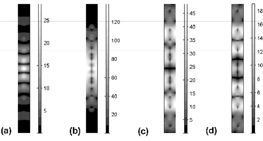
Fig. 11. Electric field distribution at 0 x a and 0 y D, D11a, for configuration A when (a) 0 and ka2.023, (b) 30o and ka3.1503, (c) 45o and
3.1008
ka ,
(d) o 45
and ka3.1583; units at the scale bar indicate the extent of magnitude enhancement as compared to the incident wave.
For smaller values of N, e.g., N5, Q103 has been obtained in configurations similar
to A and B for some of the maxima of T1 (but not for multiple maxima) with the well pronounced stop bands in between. To compare, the multiple narrow transmission peaks and large values of Q that are relevant to strong light confinement have been observed previously in circular photonic crystals, which represent another class of the defect-free rod-type structures [33].
As mentioned above, sharp transmission peaks should correspond to strong field enhancement inside the slab of PhC, which is connected with the wave slowness. Four examples of the electric field distribution at the peaks of T1, within one grating period, i.e., at 0 x a and 0 y D, D11a (see Fig. 1) are shown in Fig. 11. It can be seen that the field inside the slab can be much stronger than that of the incident wave, whose magnitude is assumed to be unity. However, in contrast to the uniform PhCs with defect(s), the regions of field enhancement are large and cannot be predicted a priori based only on the
geometrical features. By comparing the cases (a), (b), (c) and (d) in Fig. 11, one can see that various field distributions are possible, which may differ in the location of the subregions of the strongest enhancement inside the slab and the maximal enhancement ratio. Figure 11 is expected to illustrate all of the basic features of the field, even though the accuracy of these results could further be improved.
Fig. 12. Geometry of two one-dimensional multilayer structures at 0 x a and 0 y D, 8
D a (a,c), and fragments of the corresponding dependencies of T on ka (b,d); layers shown in black - 12.25 (Si), layers shown in light gray - 2.05 (SiO2).
The regimes with higher diffraction orders that might propagate in the incidence and exit air half-spaces have not been considered up to now. Thus, one may expect that similar behavior of transmission as in Figs. 4-10 can be obtained in chirped one-dimensional multilayer structures. Two examples are presented in Fig. 12. Here, two commonly used optical materials, Si and SiO2, have been chosen to create multilayer structures. The
thicknesses of the individual layers gradually vary from the middle of the slabs toward the interfaces. Clearly, another combination of the materials, e.g., Al2O3 and air, could be used
for direct comparison with the above considered two-dimensional chirped PhCs. The spatial inversion symmetry is assumed to be preserved. Although the considered structures are laterally homogeneous, the units of ka are still used in order to enable a better comparison with the results presented above for the two-dimensional rod-type structures.
The dependencies of T on ka in Fig. 12 demonstrate the possibility of obtaining multiple narrow peaks of T1, which are well separated from each other. One can see in Fig. 12(d) that at least seven well separated peaks can be obtained. However, such high values of the Q-factor as those reported above for the two-dimensional PhCs have not been obtained. For example, Q2.6 10 3 for the narrowest among the three peaks of T arising in the vicinity of
5
ka in Fig. 12(b). The peaks shown in Fig. 12(d) have Q103. Furthermore, Q exceeds 3
3 10 for some of them. At the same time, a single peak of T (not shown) has been observed in the vicinity of ka3.5 for the structure in Fig. 12(c). At smaller values of ka, dependence of T on ka looks similarly to that for uniform PhCs, i.e., it represents rather wide alternating pass and stop bands.
5. Effect of higher diffraction orders
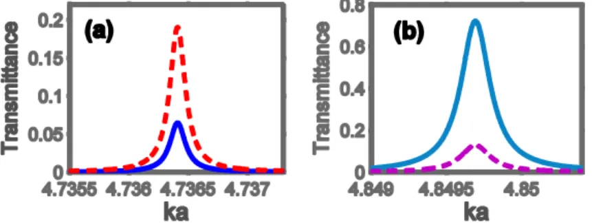
Let us briefly consider transmission through the slab of a chirped PhC when at least one of the higher diffraction orders is propagating in the incidence and exit air regions and, thus, may contribute to transmission. Multiple maxima of T also appear in this regime. However, they are not so well pronounced as in the case of the diffraction free regimes that are studied in Sections 3 and 4. Zero (t0) and first negative (t1) order transmittances are shown in Fig.
13 at the two typical maxima of T t0 t1, for configuration B. One can see that the roles of
order m 1 provides the main contribution to T at the maximum in Fig. 13(a). This occurs in spite of the fact that these two maxima are located quite close to each other. Note that similar differences have been observed for the slabs of uniform two-dimensional PhCs with defects, e.g., see Figs. 6-8 in [16]. The diffraction angle m for the order m 1 can be obtained from
1
sin sin2 ka.
Here, 1 is assumed to be measured in the counter-clockwise direction from the normal to the exit interface for transmission and θ is measured from the normal to the illuminated interface for incidence. For the maximum in Fig. 13(a), o
1 38.3
so that the larger portion of the transmitted energy is connected with the negatively deflected beam. In this case, the difference between the directions of the incident and transmitted beams is 68.3 . o
Fig. 13. Transmittance for configuration B at r11.4 and o 30
in the vicinity of (a) 4.736
ka and (b) ka4.85; solid line - m0, dashed line - m 1.
Fig. 14. Transmittance for configuration A at r9.61 and o 45
in the vicinity of (a) 4.22
ka , (b) ka4.71, and (c) ka4.845; solid line - m0, dashed line - m 1.
Finally, Fig. 14 presents t0 and t1 as a function of ka, at the maxima of T for
configuration A. Similarly to Fig. 13, there are maxima of T with the main contribution coming from the zero order as in Figs. 14(a) and 14(c) and the first negative order as in Fig. 14(b). Furthermore, the order m 1 may be the main contributor to T for both neighboring maxima, see Fig. 14(b). The use of multiple maxima, to which higher orders may contribute, gives an additional degree of freedom regarding the directions of the outgoing waves.
6. Conclusions
To summarize, multiple slow waves, relevant multiple peaks of perfect transmission, which are well separated from each other, and high-Q regimes can be obtained for non-channeled transmission through the slabs of chirped PhCs, in the direction of varying structural parameters from one unit cell to another. All of the basic transmission and dispersion features that are known for the uniform (non-chirped) PhCs with defects, which are perpendicular to
the propagation direction and, therefore, do not work as defect-mode waveguides, can be obtained in the suggested chirped structures. In addition, some regimes in uniform PhCs without defects can be replicated. The obtained results indicate a route to quite compact performances, which may be interesting for applications requiring a large number of narrow transmission bands. It has been shown that the chirping scheme based on the gradual variation of the rod diameter can yield a larger number of the slow waves in a fixed frequency range. In turn, the scheme based on the gradual variation of the distance between the neighboring rods, which are identical to each other, is expected to enable larger Q-values. Very narrow bands, corresponding to either positive or negative refraction, have been demonstrated by using both of the chirping schemes. Minimal values of the group index of refraction that correspond to the middle of a narrow band can exceed 180. Multiple bands with the middle-band index minn being larger than 20, or even 40, can be obtained in one configuration. Much larger g
values of n are typical for the band edges. The values of Q-factor of the order of 10g 4 and 105 have been demonstrated but even larger Q-values might be obtained based on the same or similar schemes. Performance enhancement will be the subject of one of our future studies. It is noteworthy that the route to multiple slow waves and relevant multiband perfect transmission is expected to be rather general. It should not necessarily require the use of one of the two chirping schemes that have been considered in this paper.
Acknowledgments
This work is supported by the projects DPT-HAMIT, ESF-EPIGRAT, and NATO-SET-181, and by TUBITAK under Project Nos., 107A004, 109A015, 109E301, and 110T306. A.E.S. thanks TUBITAK for partial support in the framework of the Visiting Researcher Program. H.K. and E.O. acknowledge partial support from the Turkish Academy of Sciences.