In this paper we present a new current-mode electronically tunable universal filter using only plus-type current controlled conveyors (CCCII+s) and grounded capacitors. The proposed circuit can simultaneously realize lowpass, bandpass, and highpass filter functions— all at high impedance outputs. The realization of a notch response does not require additional active elements. The circuit enjoys an independent current control of parameters ωo and ωo/ Q. No element matching conditions are imposed. Both its active and passive sensitivities are low.
Keywords: Current controlled conveyors, filters, current-mode.
Manuscript received Dec. 12, 2003; revised Apr. 21, 2004.
Shahram Minaei (phone: +90 216 327 1104, email: [email protected]) is with the Department of Electronics and Communication Engineering, Dogus University, Istanbul, Turkey.
Sait Türköz (email: [email protected]) is with the Department of Electronics and Communication Engineering, Istanbul Technical University, Istanbul, Turkey.
I. Introduction
Current-mode filters using second-generation current conveyors (CCII) have received considerable attention owing to the fact that their bandwidth, linearity, and dynamic range performances are better than those of their Op-amp based counterparts [1]. Therefore, a number of universal current-mode filters based on CCII have been presented [2]-[12]. Universal filters are able to achieve more than one basic filter function simultaneously with the same topology. The presented topologies in the literature can be classified considering the number of active/passive elements (grounded or floating), the number of simultaneously realized functions, the possibility of a realization of other filter functions by a slight modification of the circuit, component matching constraints, an independent electronic adjustability of the resonant angular frequency and quality factor, active/passive sensitivities, component spread, and output impedance. A current-mode filter theoretically should exhibit high output impedance to enable easy cascadability and to enable additional filter responses by a simple connection of the outputs.
Most of the circuits presented in the literature suffer from a lack of electronic tunability [2]-[8]. By using the second-generation current controlled conveyor (CCCII) introduced by Fabre and others [13], current conveyor applications can be extended to the domain of electronically tunable functions. While the circuits reported in [9]-[11] employ CCCIIs, they suffer from the use of dual-output positive/negative type CCCIIs, which complicates the filter implementations [14]. Also, the realizations of highpass responses in [9] and [10] are
Current-Mode Electronically Tunable Universal
Filter Using Only Plus-Type Current Controlled
Conveyors and Grounded Capacitors
not in high output impedance.
On the other hand, while the circuit in [12] proposed by the authors presents all of the lowpass, bandpass and highpass responses at high impedance outputs, it suffers from the use of both the positive and negative types of the CCCII in the structure of the filter.
In this paper, we modified the circuit given in [12] to propose a new current-mode current-controlled universal filter using only plus-type CCCIIs, which is advantageous in view of integrated circuit implementation. The proposed circuit can simultaneously realize lowpass, bandpass and highpass filters all at high impedance outputs, thus permitting easy cascadability. The realization of a notch function does not require additional current conveyors as such a realization can simply be achieved by connecting the appropriate nodes. The circuit enjoys independent current-control of parameters ωo and
ωo /Q.
II. Proposed Circuit
The terminal relations of a CCCII, as shown in Fig. 1, can be characterized by , 0 0 0 1 0 0 0 ± = z x y x z x y V I V R I V I α (1)
where the positive sign denotes a positive current-controlled conveyor (CCCII+) and the negative sign denotes a negative current-controlled conveyor (CCCII−), α = 1−ε , |ε| << 1 represents the current tracking error,
o T x I V R 2 = (2) is the input resistance at terminal x, where VT is the thermal
voltage, and Io is the bias current of the CCCII. The proposed
universal filter is constructed with five CCCII+s and three grounded capacitors as shown in Fig. 2. The use of grounded capacitors is particularly attractive for integrated circuit implementation [15].
Fig. 1. An electrical symbol of the CCCII. CCCII Z Y X Io Iy Ix Vy Vx Iz Vz
Fig. 2. Proposed current-mode current-controlled universal filter. Io5 Y X CCCII + Z ⑤ IHP IBP ILP X Y CCCII + Z ④ Io4 Io3 X Y CCCII + Z ③ Y X CCCII + Z ② Io2 C2 C3 Io1 X Y CCCII + Z ① C1 Iin
By taking Io5 too high, the fifth CCCII operates as a CCII in
which Rx5 is negligible, where Rx5 is the input resistance at
terminal X of this current conveyor. The transfer functions of the proposed filter can then be given by
(
)
(
2 3)
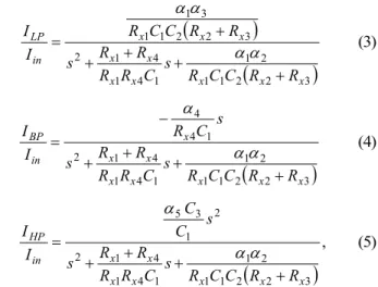
2 1 1 2 1 1 4 1 4 1 2 3 2 2 1 1 3 1 x x x x x x x x x x in LP R R C C R s C R R R R s R R C C R I I + + + + + = αα α α (3)(
2 3)
2 1 1 2 1 1 4 1 4 1 2 1 4 4 x x x x x x x x in BP R R C C R s C R R R R s s C R I I + + + + − = αα α (4)(
)
, 3 2 2 1 1 2 1 1 4 1 4 1 2 2 1 3 5 x x x x x x x in HP R R C C R s C R R R R s s C C I I + + + + = αα α (5)where Rxi and αi,i=1,L,4are the input resistance at terminal
X and the current tracking error of the i-th CCCII, respectively.
Then, the filter simultaneously realizes lowpass, bandpass, and highpass responses. From (3), (4), and (5), we can see that the gains of the lowpass, bandpass and highpass responses are as follows: . , , 1 3 5 4 1 1 4 2 3 C C G R R R G G HP x x x BP LP α α α α = + − = = (6)
By adding current outputs ILP and IHP, one can obtain a
regular notch filter for C1=C3. Note that since zero and pole
frequencies can take different values, one can also obtain lowpass notch and highpass notch filters for C1>C3 and C1<C3,
respectively. Parameters ω and o
Q
o
ω
can be given as follows:
(
2 3)
2 1 1 2 1 x x x o = R CC R +R α α ω (7) . 1 4 1 4 1 C R R R R Q x x x x o = + ω (8) From (2), (7), and (8), we can see that parameter ω can be o controlled electronically by adjusting bias current Io2 and/or3
o
I without disturbing parameter ωo/ Q. Furthermore, parameter ωo/Q can be controlled by adjusting bias current
4
o
I without disturbing parameter ω o.
Capacitor C3 and input resistance Rx5 at terminal X of the 5th
CCCII result in a dominant pole in the highpass response, which restricts the frequency range of the filter. The maximum operating frequency of the filter can be calculated as
. 2 1 3 5 max R C f x π = (9) A sensitivity analysis shows that
2 1 2 1 1 1 1 = = 2 =− =− =− =− o o o o o o o x S S S S S SRω Cω Cω Iω αω αω 0 3 2 3 2 5 4 3 3 4 = = = = = = = = = Q C Q C Q R Q R C R o o o x o x o o o o o x S S S S S S S S S ω ω ω ω ω α ω α ω α ω ω 0 5 4 3 2 1 = = = = = Q Q Q Q Q o o o o o S S S S S ω α ω α ω α ω α ω α , ) ( 2 2 3 2 2 2 x x x I R R R R S S o o o x =− =− + ω ω ) ( 2 2 3 3 3 3 x x x I R R R R S S o o o x =− =− + ω ω , 4 1 4 1 1 x x x Q I Q R R R R S S o o o x =− =− + ω ω . 4 1 1 4 4 x x x Q I Q R R R R S S o o o x =− =− + ω ω
Thus, all of the passive and active sensitivities are low.
III. Simulation Results
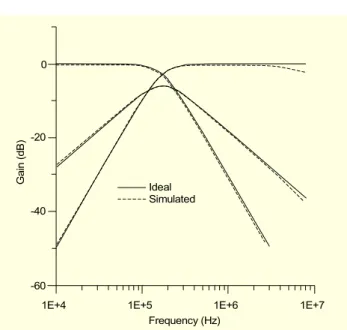
To verify the theoretical analyses, we simulated the circuit proposed in Fig. 2 using the SPICE circuit simulation program. We simulated the CCCII+s using the schematic implementation shown in Fig. 3 with a dc supply voltage of =±2.5 V. We simulated the PNP and NPN transistors in the CCCII+ implementation using the parameters of the PR100N and NR100N bipolar transistors [16]. We selected the following setting to obtain the lowpass, bandpass and highpass responses shown in Fig. 4 with a pole-natural frequency of fo=173.1 kHz
and a pole-quality factor of Q=0.707: Io1=Io4=10 µA,
Io2=Io3=40 µA, Io5=600 µA, C1=C2=C3=1 nF.
Fig. 3. The realization circuit of CCCII+. Q2 X Q4 Q6 -VEE Q5 Q12 Q11 Q9 Q8 Q3 Q1 Y Q10 Q13 Q7 +VCC Z Io
Fig. 4. The ideal and simulated lowpass, bandpass and highpass responses of the proposed circuit.
Ideal Simulated
1E+4 1E+5 1E+6 1E+7
Frequency (Hz) 0 -20 -40 -60 Ga in (d B)
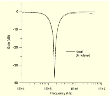
Figure 5 shows the notch response of a circuit with the same setting. The simulation results agree quite well with the theoretical analysis. The difference in the high frequency region of the highpass response stems primarily from the nonzero value of the Rx5 resistance.
The variability of natural frequency fo with bias current
Io2=Io3=Io for the bandpass response is shown in Fig. 6. We
can see that the circuit exhibits a large tuning range.
We tested the large signal behavior of the circuit by investigating the dependence of the output harmonic distortion of the bandpass response on the input signal amplitude. The obtained results are shown in Fig. 7. From Fig. 7, we can see that the harmonic distortion rapidly increases if the input signal
Fig. 5. The ideal and simulated notch responses of the proposed circuit.
Ideal Simulated
1E+4 1E+5 1E+6 1E+7
Frequency (Hz) 0 -10 -20 -30 -40 Ga in (d B)
Fig. 6. Variation of natural frequency fo with bias current Io2= Io3=Io for the bandpass response.
Ideal Simulated 1 10 Io (µA) 1000 100 10 F re que nc y ( kHz ) 100 1000
is increased beyond 150 µA for the chosen CCCII realization. For input signal levels of lower than 150 µA, the total harmonic distortion remains in acceptable limits of the order of THD = 2.5%. The results prove that the circuit operates properly even at larger signal levels in the order of 150 µA. The dependence of the output current of the filter on load resistor RL for a bandpass response is simulated for an input signal level of Iin(peak)=50 µA and a signal frequency of f=173.1 kHz.
The results are given in Table 1. From Table 1, we can easily observe that the output current level remains approximately constant, independent from the load resistor value. The output
Fig. 7. Dependence of the output harmonic distortion of the
bandpass filter on an input signal amplitude. 0 20 40 60 80 100 120 140 160 180 200 5 4 3 2 1 0 T HD ( % )
Input current (µA)
Table 1. The dependence of the output current of the bandpass filter on the load resistor RL for an input signal of f = 173.1 kHz, Iin(peak)= 50 µA. RL Iout(peak) THD (%) 100 Ω 24.88 µA 0.82 1 kΩ 24.85 µA 0.8 10 kΩ 24.73 µA 0.75 50 kΩ 23.88 µA 0.59 100 kΩ 22.16 µA 1.11 120 kΩ 19.9 µA 2.5 voltage is defined by , L out out I R V = (10) which results in the output voltage increasing linearly with an increasing load resistor when the CCCII operates in the linear operation region. Note that the circuit yields output voltage levels of up to Vout=19.9 µA×120 kΩ=2.38 V even at a
frequency of f=173.1 kHz, where the harmonic distortion remains in acceptable levels. The power consumption of the filter is 17.1 mW.
IV. Conclusion
We presented a new current-mode current-controlled universal filter with a single input and three outputs. The
proposed circuit uses the current-controlled conveyors and enjoys the following advantages: i) use of only plus-type current controlled conveyors, ii) simultaneous realization of lowpass, bandpass, and highpass filter functions without changing the circuit topology, iii) realization of the notch response does not require additional active elements, iv) an entirely independent current-control of parameters ωo and ωo
/Q, v) use of grounded capacitors—attractive for integration, and vi) low sensitivities with respect to active and passive elements.
References
[1] G.W. Roberts and A.S. Sedra, ‘‘All Current-Mode Frequency Selective Circuits,’’ Electronics Lett., vol. 25, 1989, pp. 759-761. [2] C.M. Chang, ‘‘Universal Active Current Filter with Single Input
and Three Outputs Using CCIIs,’’ Electronics Lett., vol. 29, 1993, pp. 1932-1933.
[3] C.M. Chang, ‘‘Novel Universal Current-Mode Filter with Single Input and Three Outputs Using Only Five Current Conveyors,’’ Electronics Lett., vol. 29, 1993, pp. 2005-2007.
[4] A. Fabre and M. Alami, ‘‘Universal Current Mode Biquad Implemented from Two Second Generation Current conveyors,’’ IEEE Trans. Circuits Syst.−I: Fundamental Theory and Applications, vol. 42, 1995, pp. 383-385.
[5] S. Özoğuz and C. Acar, ‘‘Universal Current-Mode Filter with Reduced Number of Active and Passive Components,’’ Electronics Lett., vol. 33, 1997, pp. 948-949.
[6] S. Özoğuz, A. Toker, and O. Çiçekoğlu, ‘‘New Current-Mode Universal Filters Using Only Four (CCII+)s,’’ Microelectronics J., vol. 30, 1999, pp. 255-258.
[7] R. Senani, ‘‘A Simple Approach of Deriving Single-Input Multiple-Output Current-Mode Biquad Filters,’’ Frequenz, vol. 50, 1996, pp. 124-127.
[8] R. Senani, ‘‘New Current-Mode Biquad Filter,’’ Int’l J. Electronics, vol. 73, 1992, pp. 735-742.
[9] M.T Abuelma’atti and N.A. Tasadduq ‘‘New Current-Mode Current-Controlled Filters Using the Current-Controlled Conveyor,’’ Int’l J. Electronics, vol. 85, 1998, pp.483-488.
[10] M.T Abuelma’atti and N.A. Tasadduq ‘‘Universal Current-Controlled Current-Mode Filter Using the Multiple-Output Translinear Current Conveyor,’’ Frequenz, vol. 52, 1998, pp. 252-254.
[11] M.T Abuelma’atti and N.A. Tasadduq ‘‘A Novel Single-Input Multiple-Output Current-Mode Current-Controlled Universal Filter,’’ Microelectronics J., vol. 29, 1998, pp. 901-905.
[12] S. Minaei and S. Türköz “New Current-Mode Current-Controlled Universal Filter with Single Input and Three Outputs,” Int’l J. Electronics, vol. 88, 2001, pp.333-337.
[13] A. Fabre, O. Saaid, F. Wiest, and C. Boucheron ‘‘Current Controlled Bandpass Filter Based on Translinear Conveyors,” Electronics Lett., vol. 31, 1995, pp.1727-1728.
[14] M. Higashimura and Y. Fukui ‘‘Universal Filter Using Plus-Type CCIIs,’’ Electronics Lett., vol. 32, 1996, pp. 810-811.
[15] K. Pal and R. Singh ‘‘Inductorless Current Conveyor Allpass Filter Using Grounded Capacitors,’’ Electronics Lett., vol. 18, 1982, p. 47.
[16] D.R. Frey ‘‘Log-Domain Filtering: an Approach to Current-Mode Filtering,’’ IEE Proc.−G, Circuits, Devices and Systems, vol. 140, 1993, pp. 406-416.
Shahram Minaei received the BS degree in electrical and electronics engineering from Iran University of Science and Technology in 1993. He received his MS and PhD degrees in electronics and communication engineering from Istanbul Technical University in 1997 and 2001, respectively. He is currently Associate Professor at the Electronics and Communication Engineering Department of Dogus University in Istanbul, Turkey. He has more than forty journal or conference papers in scientific review. He served as Program Committee Member of the Applied Electronics 2003 and 2004 Conferences and Reviewer of the 8th, 9th and 10th IEEE conferences on Electronics, Circuits and Systems (ICECS 2001, 2002 and 2003) and the 2003 IEEE International Symposium on Circuits and Systems (ISCAS 2003). His current field of research concerns current-mode circuits and analog signal processing.
Sait Türközreceived the BS, MS and PhD degrees from Istanbul Technical University in 1970, 1973 and 1981, respectively. In 1970 he joined the Electronics and Communication Engineering Department of Istanbul Technical University. Since 1993 he has been Associate Professor of electronics in the same department. His research interest includes electronic circuits, active filters, and design of analog IC topologies. He is the author of many publications and books.