ELECTROSPINNING of BIOCOMPATIBLE POLYMERIC
NANOFIBERS FUNCTIONALIZED with CYCLODEXTRIN
INCLUSION COMPLEX
A THESIS
SUBMITTED TO THE MATERIALS SCIENCE AND NANOTECHNOLOGY
PROGRAM OF GRADUATE SCHOOL OF ENGINEERING AND SCIENCE
OF BILKENT UNIVERSITY
IN PARTIAL FULFILLMENT OF THE REQUIREMENTS
FOR THE DEGREE OF
MASTER OF SCIENCE
By Zeynep Aytaç
ii
I certify that I have read this thesis and that in my opinion it is fully adequate, in scope and in quality, as a thesis of the degree of Master of Science.
……… Assist. Prof. Dr. Tamer Uyar (Advisor)
I certify that I have read this thesis and that in my opinion it is fully adequate, in scope and in quality, as a thesis of the degree of Master of Science.
………. Assist. Prof. Dr. Turgay Tekinay
I certify that I have read this thesis and that in my opinion it is fully adequate, in scope and in quality, as a thesis of the degree of Master of Science.
………. Assist. Prof. Dr. Fatih Büyükserin
Approved for the Graduate School of Engineering and Science:
………. Prof. Dr. Levent Onural
iii
ABSTRACT
ELECTROSPINNING of BIOCOMPATIBLE POLYMERIC
NANOFIBERS FUNCTIONALIZED with CYCLODEXTRIN
INCLUSION COMPLEX
Zeynep Aytaç
M.S. in Materials Science and Nanotechnology Supervisor: Assist. Prof. Dr. Tamer Uyar
August, 2012
Electrospinning is a simple, versatile and cost-effective method to produce nanofibers. Electrospun nanofibers have high surface area to volume ratio and nanoporous structure. Moreover, electrospun nanofibers could be functionalized with additives to extend their application areas. Cyclodextrins (CDs) are cyclic oligosaccharides and have truncated-cone shape structure. Due to their hydrophobic cavity, CDs have ability to form inclusion complex (IC) with a variety of molecule. In our study, we functionalized electrospun nanofibers with CDs and CD-ICs.
In the first part, we successfully produced hydroxypropyl cellulose- (HPC), carboxymethyl cellulose- (CMC) and alginate-based nanofibers via electrospinning. Then we functionalized these nanofibers with CDs. The morphological characterizations of nanofibers were performed through scanning electron microscopy (SEM). Here, we have combined the properties of both electrospun nanofibers and CDs, and these nanofibers could be used in drug delivery, wound healing and tissue engineering applications.
iv
In the second part, we prepared IC of sulfisoxazole (SFS) (hydrophobic drug) with hydroxypropyl-beta-cyclodextrin (HPβCD) (SFS/HPβCD-IC). Then electrospinning of SFS/HPβCD-IC incorporating hydroxypropyl cellulose (HPC) nanofibers were performed (SFS/HPβCD-IC-HPC-NFs). In the third part of our study, we produced IC of α-tocopherol (α-TC) (antioxidant molecule) with beta-cyclodextrin (β-CD) (α-TC/β-CD-IC); and polycaprolactone (PCL) nanofibers incorporating α-TC/β-CD-IC was obtained via electrospinning (α-TC/β-CD-PCL-NFs). In the fourth part, IC of allyl isothiocyanate (AITC) (antibacterial compound) with β-CD (AITC/β-CD-IC) was produced. The electrospinning of AITC/β-CD-IC incorporating polyvinyl alcohol (PVA) nanofibers was carried out (AITC/β-CD-IC-PVA-NFs). In the fifth part, IC of quercetin (QU) (antioxidant molecule) with β-CD (QU/β-CD-IC) was prepared; and polyacrylic acid (PAA) nanofibers incorporating QU/β-CD-IC was obtained via electrospinning (QU/β-CD-IC-PAA-NFs). The structural and thermal characterizations of SFS/HPβCD-IC-HPC-NFs, α-TC/β-CD-PCL-NFs, AITC/β-CD-IC-PVA-NFs and QU/β-CD-IC-PAA-NFs were carried out by scanning electron microscopy (SEM), X-ray diffraction (XRD), differential scanning calorimetry (DSC) and thermogravimetric analysis (TGA). The amount of released molecules were determined via liquid chromatography-mass spectroscopy (LC-MS) for SFS/HPβCD-IC-HPC-NFs; high performance liquid chromatography (HPLC) for α-TC/β-CD-PCL-NFs and QU/β-CD-IC-PAA-NFs and gas chromatography-mass spectrometry (GC-MS) for AITC/β-CD-IC-PVA-NFs. The antioxidant activity of α-TC/β-CD-PCL-NFs and QU/β-CD-IC-PAA-NFs was investigated by using 2,2-diphenyl-1-picrylhydrazyl (DPPH) radical scavenging assay. Moreover, α-TC/β-CD-PCL-NFs released great proportion of α-TC after exposing UV light. Thus, α-TC/β-CD-PCL-NFs exhibited quite high photostability. The antibacterial activity of AITC/β-CD-IC-PVA-NFs was evaluated by colony counting method against Escherichia coli (E.coli) and Staphylococcus aureus (S.aureus). In brief, we concluded that SFS/HPβCD-IC-HPC-NFs, α-TC/β-CD-PCL-NFs, AITC/β-CD-IC-PVA-NFs and QU/β-CD-IC-PAA-NFs are promising materials for drug delivery and wound healing applications.
v
Keywords: electrospinning, nanofibers, biopolymers, cyclodextrin, inclusion complex, sulfisoxazole, α-tocopherol, allyl isothiocyanate, quercetin, controlled release.
vi
ÖZET
ELEKTROEĞĠRME YÖNTEMĠ ĠLE SĠKLODEKSTRĠN
ĠNKLÜZYON KOMPLEKSLERĠYLE
FONKSĠYONLAġTIRILMIġ BĠYOUYUMLU NANOLĠFLERĠN
ÜRETĠLMESĠ
Zeynep Aytaç
Yüksek Lisans, Malzeme Bilimi ve Nanoteknoloji Bölümü Tez Yöneticisi: Yard. Doç. Dr. Tamer Uyar
Ağustos, 2012
Elektroeğirme nanolif elde etmek için basit, verimli ve maliyeti düĢük bir yöntemdir. Elektroeğirme yöntemiyle elde edilen nanolifler yüksek yüzey alanına ve nano boyutta gözenekli yapıya sahiptir. Dahası, bu nanolifler uygulama alanlarını geniĢletmek amacıyla katkı maddeleri ile fonksiyonel hale getirilebilirler. Siklodekstrinler (CD), kesik koni Ģeklindeki siklik oligosakkaritlerdir. Hidrofobik kaviteleri sayesinde, pek çok molekülle inklüzyon kompleksi (IC) oluĢturabilirler. ÇalıĢmalarımızda, elektroeğirme yöntemiyle elde edilen nanolifleri CD ve CD-IC ile fonksiyonel hale getirdik.
Ġlk kısımda, hidroksipropil selüloz (HPC), karboksimetil selüloz (CMC) ve aljinat nanoliflerini elektroeğirme yöntemi ile baĢarıyla ürettik. Daha sonra bu nanolifleri CD’lerle fonksiyonel hale getirdik. Bu nanoliflern morfolojik karakterizasyonları taramalı electron mikroskobu (SEM) yardımıyla yapıldı. Burada, elektroeğirme ile üretilen nanoliflerin ve CD’lerin özelliklerini
vii
birleĢtirmiĢ olduk. Bu nanolifler ilaç salımı, yara iyileĢtirme ve doku mühendisliği alanlarında kullanılabilirler.
Ġkinci kısımda, sülfisoksazol (SFS) (hidrofik ilaç) ile hidroksipropil-beta-siklodekstrin (HPβCD) inklüzyon kompleksini (IC) (SFS/HPβCD-IC) hazırladık. Daha sonra SFS/HPβCD-IC içeren hidroksipropil selüloz (HPC) nanolifleri elektroeğirme yöntemiyle üretildi. ÇalıĢmamızın üçüncü kısmında, α-tokoferol (α-TC) (antioksidan madde) ile beta-siklodekstrin (β-CD) IC (α-TC/β-CD-IC) ürettik; ve α-TC/β-CD-IC içeren polikprolakton (PCL) nanolifleri elektroeğirme ile elde edildi (α-TC/β-CD-IC-PCL-NFs). Dördüncü kısımda, alil izotiyosiyanat (AITC) (antibakteriyel madde) ile β-CD IC (AITC/β-CD-IC) üretildi. AITC/β-CD-IC içeren polivinil alkol (PVA) nanolifleri elektroeğirme ile üretildi (AITC/β-CD-IC-PVA-NFs). BeĢinci kısımda, kuersetin (QU) (antioksidan madde) ile β-CD IC (QU/β-CD-IC) hazırlandı ve QU/β-CD-IC içeren poliakrilik asit (PAA) nanolifleri elektroeğirme ile elde edildi (QU/β-CD-IC-PAA-NFs). SFS/HPβCD-IC-HPC-NFs, α-TC/β-CD-IC-PCL-NFs, AITC/β-CD-IC-PVA-NFs ve QU/β-CD-IC-PAA-NFs’nin yapısal ve ısıl karakterizasyonları taramalı elektron mikroskobu (SEM), X-ıĢını kırınımı (XRD), diferansiyel tarama kalorimetrisi (DSC) ve termogravimetrik analiz (TGA) ile yapıldı. Nanoliflerden salınan moleküllerin miktarı SFS/HPβCD-IC-HPC-NFs için sıvı kromatografisi-kütle spektrometresi (LC-MS); α-TC/β-CD-IC-PCL-NFs ve QU/β-CD-IC-PAA-NFs için yüksek performanslı sıvı kromatografisi (HPLC) ve AITC/β-CD-IC-PVA-NFs için gaz kromatografisi- kütle spektrometresi (GC-MS) yardımıyla belirlendi. α-TC/β-CD-IC-PCL-NFs ve QU/β-CD-IC-PAA-NFs’nin antioksidan aktivitesi 2 2-difenil-1-pikrilhidrazil (DPPH) radikal temizleme testiyle incelendi. Dahası, α-TC/β-CD-PCL-NFs UV ıĢığına maruz bırakıldıktan sonra da α-TC’nin büyük bir kısmını salmıĢtır. Bu nedenle, α-TC/β-CD-IC-PCL-NFs oldukça yüksek fotostabilite göstermiĢtir. AITC/β-CD-IC-PVA-NFs’nin Escherichia coli (E.coli) and Staphylococcus aureus’a karĢı antibakteriyel etkisi koloni sayma metoduyla belirlendi. Kısacası, SFS/HPβCD-IC-HPC-NFs, α-TC/β-CD-IC-PCL-NFs,
AITC/β-CD-IC-PVA-viii
NFs ve QU/β-CD-IC-PAA-NFs’nin ilaç salımı ve yara iyileĢtirme uygulamalarında gelecek vadeden malzemeler oldukları sonucunda vardık.
Anahtar Kelimeler: elektroeğirme, nanolif, biyopolimer, siklodekstrin, inklüzyon kompleks, sülfisoksazol, α-tokoferol, alil izotiyosiyanat, kuersetin, kontrollü salım.
ix
ACKNOWLEDGEMENT
I would like to express my sincerest gratitude to my supervisor Assist. Prof. Dr. Tamer Uyar for his guidance, support, patience and providing me with an excellent atmosphere for doing research.
I would like to thank the members of my group members Aslı Çelebioğlu, Fatma Kayacı and Yelda ErtaĢ for their support and valuable friendship.
I would like to thank Asst. Prof. Dr. Turgay Tekinay and his student Özgün Candan Onarman Umu for their collaboration in antibacterial test experiments. I would like to acknowledge State Planning Organization (DPT) of Turkey for its support to UNAM Institute of Materials Science and Nanotechnology, and The Scientific and Technological Research Council of Turkey (TÜBĠTAK) for their financial support.
I would also like to thank my parents, my sister Ġrem Aytaç and Damla Uzun for their understanding, support and encouragement.
x
TABLE OF CONTENTS
ABSTRACT ... iii ÖZET ... vi ACKNOWLEDGEMENT ... ix TABLE OF CONTENTS ... xLIST OF FIGURES ... xiii
LIST OF TABLES ... xvii
PART I. ... 1
INTRODUCTION ... 1
1.1. Electrospinning ... 1
1.2. Electrospinning of biopolymers and biodegradable polymers ... 6
1.3. Cyclodextrins ... 8
PART II. ... 12
CHAPTER I. ELECTROSPINNING of POLYSACCHARIDES FUNCTIONALIZED with CYCLODEXTRINS ... 12
2.1. General Information ... 12
2.2. Materials ... 15
2.3. Electrospinning unit at UNAM ... 15
2.4. Production of electrospun nanofibers ... 16
2.5. Measurements and characterization techniques ... 18
2.6. Results and discussion ... 18
2.6.1. Electrospinning of CD functionalized HPC nanofibers ... 18
xi
2.6.3. Electrospinning of CD functionalized alginate nanofibers ... 26
2.7. Conclusion ... 30
CHAPTER II. RELEASE of SULFISOXAZOLE from ELECTROSPUN HYDROXYPROPYL CELLULOSE NANOFIBERS INCORPORATING CYCLODEXTRIN INCLUSION COMPLEX ... 31
3.1. General Information ... 31
3.2. Materials ... 32
3.3. Production of electrospun nanofibers ... 33
3.4. Preparation of phosphate buffer ... 34
3.5. Drug release assay ... 34
3.6. Measurements and characterization techniques ... 35
3.7. Results and discussion ... 36
3.8. Conclusion ... 45
CHAPTER III. RELEASE of α-TOCOPHEROL (VITAMIN E) from ELECTROSPUN POLYCAPROLACTONE NANOFIBERS INCORPORATING CYCLODEXTRIN INCLUSION COMPLEX ... 46
4.1. General Information ... 46
4.2. Materials ... 47
4.3. Production of electrospun nanofibers ... 48
4.4. Preparation of phosphate buffer ... 48
4.5. Drug release assay ... 49
4.6. Measurements and characterization techniques ... 49
4.7. Results and discussion ... 51
xii
CHAPTER IV. RELEASE of ALLYL ISOTHIOCYANATE from
ELECTROSPUN POLYVINYL ALCOHOL NANOFIBERS INCORPORATING
CYCLODEXTRIN INCLUSION COMPLEX ... 62
5.1. General Information ... 62
5.2. Materials ... 63
5.3. Production of electrospun nanofibers ... 63
5.4. Measurements and characterization techniques ... 64
5.5. Results and discussion ... 66
5.6. Conclusion ... 71
CHAPTER V. RELEASE of QUERCETIN from ELECTROSPUN POLYACRYLIC ACID NANOFIBERS INCORPORATING CYCLODEXTRIN INCLUSION COMPLEX ... 72
6.1. General Information ... 72
6.2. Materials ... 73
6.3. Production of films and electrospun nanofibers ... 74
6.4. Preparation of phosphate buffer ... 74
6.5. Drug release assay ... 75
6.6. Measurements and characterization techniques ... 75
6.7. Results and discussion ... 76
6.8. Conclusion ... 82
CHAPTER VI. ... 84
CONCLUSION ... 84
xiii
LIST OF FIGURES
Figure 1. Schematic view of electrospinning. ... 2
Figure 2. Effect of concentration in electrospinning of carboxymethyl cellulose (CMC)/polyethyleneoxide (PEO) nanofibers: a) 2.25% 0.75%PEO, b) 3% CMC-1%PEO. ... 3
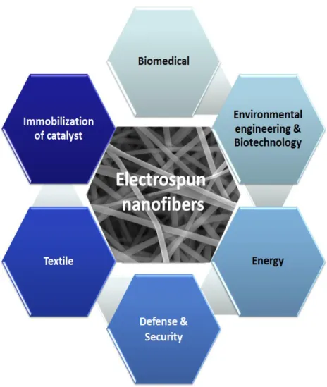
Figure 3. Applications of electrospun nanofibers. ... 5
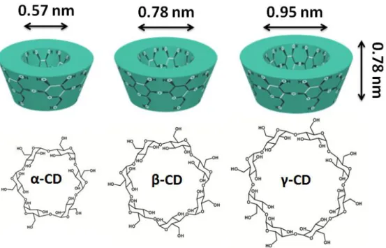
Figure 4. Schematic views and chemical structures of α-CD, β-CD, γ-CD. ... 9
Figure 5. Schematic view of inclusion complex formation between CD and guest molecule. ... 10
Figure 6. Chemical structure of HPC. ... 13
Figure 7. Chemical structure of CMC. ... 14
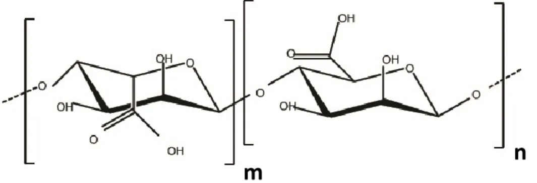
Figure 8. Chemical structure of alginate. ... 14
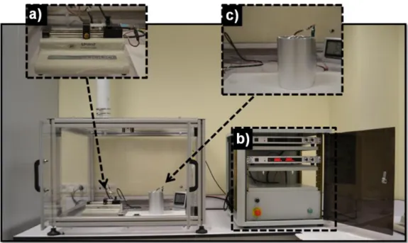
Figure 9. Electrospinning unit at UNAM: a) syringe pump, b) high voltage supply, and c) collector. ... 16
Figure 10. SEM images of electrospun (a) 3% (w/v) HPC; (b) 3% (w/v) HPC and 1% (w/v) Triton X-100, (c) 3.5% (w/v) HPC and 1% (w/v) Triton X-100, (d) 4% (w/v) HPC and 1% (w/v) Triton X-100 solutions in aqueous solution. ... 19
Figure 11. SEM images of electrospun HPC (3% (w/v)) nanofibers: (a) in ethanol/water (1:1), (b) in ethanol, (c) in ethanol/2-propanol (1:1). ... 19
Figure 12. SEM images of electrospun HPC (3% (w/v)) nanofibers incorporated (a) 25% (w/w) HPβ-CD, (b) 50% (w/w) HPβ-CD, (c) 100% (w/w) HPβ-CD; (d) 25% (w/w) Mβ-CD, (e) 50% (w/w) Mβ-CD, (f) 100% (w/w) Mβ-CD; (g) 25% (w/w) HPγ-CD, (h) 50% (w/w) HPγ-HPγ-CD, (i) 100% (w/w)HPγ-CD in ethanol. ... 20
Figure 13. SEM images of electrospun CMC/PEO solutions at 1:1 ratio with different total polymer concentrations: (a) 2%, (b) 3%, (c) 4% (w/v). ... 23
Figure 14. SEM images of electrospun CMC/PEO solutions at 3:1 ratio with different total polymer concentrations: (a) 2%, (b) 3%, (c) 4% (w/v). ... 23
xiv
Figure 15. SEM images of electrospun CMC/PEO (3:1) nanofibers incorporated (a) 25% (w/w) HPβ-CD, (b) 50% (w/w) HPβ-CD, (c) 100% (w/w) HPβ-CD; (d) 25% (w/w) Mβ-CD, (e) 50% (w/w) Mβ-CD, (f) 100% (w/w) Mβ-CD; (g) 25% (w/w) HPγ-CD, (h) 50% (w/w) HPγ-HPγ-CD, (i) 100% (w/w) HPγ-CD in aqueous solution. ... 24 Figure 16. SEM images of electrospun alginate/PEO solutions at 1:1 ratio with
different total polymer concentrations (a) 4% (w/v), (b) 5% (w/v) in aqueous solution. ... 27 Figure 17. SEM images of electrospun alginate/PEO solutions with 3% (w/v) total polymer concentrations and different ratios (a) 62:28 (b) 75:25; 4% (w/v) total polymer concentrations and different ratios (c) 62:28 (d) 75:25 in aqueous solution. ... 28 Figure 18. SEM images of electrospun alginate/PEO solutions with 3% (w/v) total polymer concentrations and different ratios (a) 62:28 (b) 75:25; 4% (w/v) total polymer concentrations and different ratios (c) 62:28 (d) 75:25 in aqueous solution including 1% (w/v) Triton X-100... 28 Figure 19. SEM images of electrospun alginate/PEO (62:28) nanofibers incorporated (a) 25% (w/w) HPβ-CD, (b) 50% (w/w) HPβ-CD; (c) 25% (w/w) HPγ-CD, (d) 50% (w/w) HPγ-CD in aqueous solution including 1% (w/v) Triton X-100. ... 30 Figure 20. Chemical structure of (a) SFS, (b) HPβ-CD; schematic representation of (c) HPβ-CD, and (d) SFS/HPβ-CD-IC. ... 33 Figure 21. Schematic representation of release of SFS from SFS/HPβ-CD-IC-HPC-NFs. ... 35 Figure 22. SEM images and AFD distributions of (a) electrospun HPC nanofibers, (b) SFS-HPC-NFs, (c) SFS/HPβ-CD-IC-HPC-NFs. ... 38 Figure 23. SEM image of electrospun PCL nanofibers. ... 39 Figure 24. XRD patterns of (a) SFS, (b) electrospun HPC nanofibers, (c) HPβ-CD, (d) SFS-HPC-NFs, (e) SFS/HPβ-CD-IC-HPC-NFs. ... 40 Figure 25. DSC thermograms of (a) SFS, (b) SFS-HPC-NFs, (c) SFS/HPβ-CD-IC-HPC-NFs. ... 41
xv
Figure 26. TGA thermograms of (a) SFS, (b) electrospun HPC nanofibers, (c) HPβ-CD, (d) SFS-HPC-NFs, (e) SFS/HPβ-CD-IC-HPC-NFs. ... 42 Figure 27. Cumulative release profiles of (a) SFS-HPC-NFs, (b) SFS/HPβ-CD-IC-HPC-NFs. ... 45 Figure 28. Chemical structure of (a) α-TC, (b) CD; schematic representation of (c) β-CD, and (d) α-TC/β-CD-IC. ... 47 Figure 29. SEM images and AFD distributions of (a) electrospun PCL nanofibers, (b) α-TC-PCL-NFs, (c) α-TC/β-CD-IC-PCL-NFs. ... 52 Figure 30. XRD patterns of (a) electrospun PCL nanofibers, (b) β-CD, (c) α-TC-PCL-NFs, (d) α-TC/β-CD-IC-PCL-NFs. ... 53 Figure 31. DSC thermogram of (a) α-TC, (b) electrospun PCL nanofibers (c) β-CD, (d) α-TC-PCL-NFs, (e) α-TC/β-CD-IC-PCL-NFs. ... 54 Figure 32. TGA thermograms of (a) α-TC, (b) electrospun PCL nanofibers (c) β-CD, (d) α-TC-PCL-NFs, (e) α-TC/β-CD-IC-PCL-NFs. ... 55 Figure 33. Cumulative release profiles of (a) α-TC-PCL-NFs, (b) α-TC/β-CD-IC-PCL-NFs. ... 57 Figure 34. SEM images of (a) α-TC-PCL-NFs, (b) α-TC/β-CD-IC-PCL-NFs after HPLC. ... 57 Figure 35. Percent of released α-TC from α-TC-PCL-NFs and α-TC/β-CD-IC-PCL-NFs after UV treatment for 45 minutes. ... 58 Figure 36. SEM images of (a) α-TC-PCL-NFs, (b) α-TC/β-CD-IC-PCL-NFs after UV treatment for 45 minutes. ... 58 Figure 37. Antioxidant activity of (a) electrospun PCL nanofibers, (b) α-TC-PCL-NFs, (c) α-TC/β-CD-IC-PCL-NFs. ... 60 Figure 38. Chemical structure of (a) AITC, (b) β-CD; schematic representation of (c) β-CD, and (d) AITC/ β-CD-IC. ... 63 Figure 39. SEM images and AFD distributions of (a) electrospun PVA nanofibers, (b) AITC/β-CD-IC-PVA-NFs. ... 67
xvi
Figure 40. XRD patterns of (a) electrospun PVA nanofibers, (b) β-CD, (c) AITC/β-CD-IC-PVA-NFs. ... 68 Figure 41. TGA thermograms of (a) AITC, (b) electrospun PVA nanofiber, (c) βCD, (d) AITC/βCD inclusion complex incorporated electrospun PVA nanofibers. ... 69 Figure 42. Cumulative release of (a) AITC-PVA-NFs, (b) AITC/β-CD-IC-PVA-NFs. ... 70 Figure 43. Exemplary images of (a) control sample - colonies of E.coli and (b)
S.aureus; c) E.coli colonies and (d) S.aureus colonies treated by AITC/β-CD-IC-PVA-NFs; (e) antibacterial activity of AITC/β-CD-IC-PVA-NFs against E.coli and S.aureus. ... 71 Figure 44. Chemical structure of (a) QU, (b) CD; schematic representation of (c) β-CD, and (d) QU/β-CD-IC. ... 73 Figure 45. SEM images and AFD distributions of QU/β-CD-IC-PAA-NFs before crosslink. ... 77 Figure 46. SEM images of QU/β-CD-IC-PAA-NFs after crosslink. ... 77 Figure 47. XRD patterns of (a) QU, (b) PAA, (c) βCD, (d) QU/β-CD-IC-PAA films, (e) QU/β-CD-IC-PAA-NFs... 78 Figure 48. TGA thermograms of (a) QU, (b) PAA, (c) βCD, (d) QU/β-CD-IC-PAA films, (e) QU/β-CD-IC-PAA-NFs. ... 79 Figure 49. Cumulative release profiles of (a) IC-PAA-films, (b. QU/β-CD-IC-PAA-NFs. ... 81 Figure 50. UV-vis spectrum of (a) DPPH, (b) QU/β-CD-IC-PAA-films including DPPH solution, (c) QU/β-CD-IC-PAA-NFs including DPPH solution. ... 82
xvii
LIST OF TABLES
Table 1. General properties of cyclodextrins [39]. ... 9 Table 2. The characteristics of HPC solution and CD incorporated HPC solutions and the resulting electrospun fibers. ... 21 Table 3. The characteristics of CMC, CMC/PEO and CD incorporated CMC solutions and the resulting electrospun fibers... 26 Table 4. The characteristics of HPC solution, SFS-HPC solution and SFS/HPβ-CD-IC- HPC solutions and the resulting electrospun fibers. ... 38 Table 5. The characteristics of PCL, α-TC-PCL and α-TC/βCD-IC- PCL solutions and the resulting electrospun fibers. ... 52
1
PART I.
INTRODUCTION
1.1. Electrospinning
Nanofibers with their porous structure and high surface-to-volume ratio are highly promising materials that can be used in various applications. There are many methods to produce nanofibers like drawing, template synthesis, phase separation, self-assembly, electrospinning, etc. [1]. Among these methods, electrospinning is a universal method to produce nanofibers having diameter ranging from 10 nanometers to a few microns [2]. In electrospinning, one can use polymers, polymer blends, sol-gels and ceramic precursors to obtain nanofibers and different structures such as core-shell, hollow, ribbon-like, porous and aligned nanofibers can be produced [3]. Electrospinning is superior to other methods with its relatively low cost, high production rate and simplicity [4]. In addition to unique properties of nanofibers, electrospun nanofibers are easily functionalized with nanoparticles, additives, bioactive agents; therefore, multifunctional electrospun nanofibers can be produced [5].
Electrospinning set-up has three main components; these are high voltage power supply, syringe pump and grounded collector (Figure 1). The basic principle of electrospinning relies on formation of nanofibers through electric field. The solution in a syringe is pumped through the outlet of the spinneret at a controlled rate by means of syringe pump. At the same time, high voltage in 10-30 kV range is applied from high voltage power supply; particles within the solution are charged and create a repulsive force; this results in deformation of drop in cone-shaped named as Taylor cone. When threshold voltage value is surpassed, the repulsive force overcomes the surface tension of the solution and polymer jet is formed in the tip of spinneret. While aforementioned jet going towards the grounded collector, the solvent evaporates and nanofibers are collected on the collector [1,4].
2
Electrospun nanofibers Polymer
solution
High voltage power supply
Syringe pump 15 kV
Figure 1. Schematic view of electrospinning.
The history of electrospinning dates back to 1900s; electrical charge was firstly used to spray liquids by Cooley and his studies was patented in 1902 [6-8]. Then, Formhals received a patent which is on electrospinning of polymer filaments [9]. After almost 40 years, Simm et al. produced nanofibers which have diameter below 1μm via electrospinning and this study was patented as well [10]. But until 1990s there was no significant study on this technique. In early 1990s, Reneker’s group started to study on electrospinning [11-13] and this technique has gained reputation. Today it is being used by many research groups as well as industries all around the world.
In regard to parameters of electrospinning, there exist three main groups: polymer/solution parameters, processing conditions and environmental conditions [1]. In order to obtain uniform nanofibers with electrospinning, one should optimize all these parameters. First of all, polymer/solution parameters are of vital importance for electrospinning. These are type, molecular weight and molecular weight distribution of the polymer; surface tension, dielectric constant, conductivity, concentration and viscosity of the solution [1]. Initially, molecular weight and concentration are the factors affecting viscosity of the polymer solution. Since certain amount of viscosity is required for a polymer solution to be electrospun, polymer with suitable molecular weight and concentration should be used to obtain electrospun nanofibers. Effect of increasing concentration (viscosity) on electrospinning of carboxymethyl
3
cellulose (CMC) was shown in Figure 2. Secondly, as conductivity of the solution increases, more charges are formed in the solution, so stretching of the solution increases. As a result, nanofibers with a smaller diameter are obtained. Thirdly, impact of dielectric constant of the solvent should be considered. While the dielectric constant of the solution rises; electrospinnability of solution is improved, and diameter of the solutions reduces. Last but not least, surface tension has an influence on formation of nanofibers from electrospinning. Because in order nanofibers to be formed; surface tension of polymer solution must be overcame by electrical forces [1].
Figure 2. Effect of concentration in electrospinning of carboxymethyl cellulose
(CMC)/polyethyleneoxide (PEO) nanofibers: a) 2.25% CMC-0.75%PEO, b) 3% CMC-1%PEO.
On the other hand, process conditions are of secondary significance in the formation of electrospun nanofibers. These are applied voltage, distance from tip of the spinneret to collector, feed rate, needle diameter and type of the collector [1]. Basically, high voltage is required to produce nanofibers by electrospinning. Owing to high voltage, electrostatic force is formed and surface tension of polymer is surpassed. In addition, further increase in applied voltage cause formation of thinner nanofibers in diameter, because of higher electric field caused the higher stretching of solution. On the other hand, decrease in the distance from tip of the spinneret to collector lead to increase in electric field; thus, average fiber diameter decreases. Mostly, low feed rate is preferred rather than high; in order to allow solvent to evaporate. Otherwise, due to the great amount of solution fed towards to the collector, nanofibers are most likely to
4
coalesce on top of another on the collector without finding time to evaporate. The needle diameter is another factor influences the morphology and uniformity of electrospun nanofibers. First of all, it is important to use suitable needle in diameter according to the viscosity of solution. The smaller needle diameter leads to formation of small polymer droplet in the tip of the spinneret; therefore the surface tension of the so-called droplet is getting higher. So the greater amount of voltage and indirectly more time is needed nanofibers to be obtained. Finally, the collector is covered with a conductive material such as aluminum foil to increase efficiency of nanofibers’ deposition on collector. In addition, type of the collector has great contribution to achieve different kinds of structures through the use of electrospinning. For instance, aligned nanofibers could be obtained by using rotating collector in electrospinning system [1].
Lastly, environmental conditions such as temperature, humidity and pressure are of importance on the morphology of nanofibers obtained via electrospinning [1]. To illustrate, temperature rise triggers viscosity and surface tension to decrease; whereas conductivity to increase. So, average fiber diameter decreases with the increasing of temperature [14]. On the other side, the rise in humidity decelerates the evaporation of solvent; therefore average fiber diameter increases. Moreover, porous nanofibrous structure might be formed with the increase in the humidity [15].
Owing to the unique properties of electrospun nanofibers like high surface area to volume ratio, diameters at nanoscale and possibility to produce different structures from various materials; electrospun nanofibers can be used in textile [5], environmental applications (separation membranes, affinity membranes, water filter, air filter) [16]; energy (solar cells, fuel cells, supercapacitors, hydrogen storage, optoelectronics, transistor) [16]; defense&security (chemical/biological protection and sensor) [3], biomedical applications (tissue scaffolds, wound healing materials and delivery of bioactive molecules) [17-18] and immobilization of catalysts/enzymes [5] (Figure 3).
5
Figure 3. Applications of electrospun nanofibers.
Electrospun nanofibers in biomedical applications include tissue scaffolds, wound healing materials and delivery of bioactive molecules [5,17-18]. Initially, in order for a material to be used in biomedical applications; it should have high porosity that makes it to be physically similar with extracellular matrix found in native tissues and as low as possible fiber diameter (nanoscale range). Therefore electrospun nanofibers have ability to fulfill the requirements of biomedical materials thanks to its high surface to volume ratio and highly porous structure. In addition, above-mentioned unique properties of electrospun nanofibers enhance cell attachment, drug loading, and mass transfer properties as well [17]. There exist many biocompatible and biodegradable polymers that can be electrospun, this variety in polymer types make electrospun nanofibers quite applicable for biomedical applications [17]. Moreover, electrospun nanofibers
6
could be used as wound healing materials especially for burns and abrasions [5]. The large surface area to volume ratio and porous structure provide absorption of liquid and gases; releasing of the drugs at the same time; whereas protecting wounds from bacterial penetration [5,18].
1.2. Electrospinning of biopolymers and biodegradable polymers
In general, polymers are produced from non-renewable materials and not biodegradable. This situation has caused environmental problems. In order to overcome these problems, there is a gradually increasing interest in biopolymers and synthetic biodegradable polymers. Biopolymers are produced by microorganisms, plants and animals or synthesized from biological materials like amino acids, sugars etc. [19]. They have properties such as biodegradability, biocompatibility and sustainability. On the other hand, biopolymers might have different molecular weight, degree of substitution, crystallinity etc. In addition, it is very difficult to control the properties of them during processing, since different conditions should be applied even for different batches of the same polymer.
In principle, biopolymers are divided into three groups: polynucleotides (DNA, RNA), polypeptides and polysaccharides (starch, chitin, chitosan, cellulose and its derivatives; hyaluronic acid, glycogen, alginate etc.) [20]. Polysaccharides consist of several monosaccharide molecules and are linked by glycosidic bonds [19]. Cellulose is a kind of polysaccharide that can be produced by plant tissues or certain bacteria [19]. It composes of D-anhydro-glucose repeating units and linked by 1, 4-β-D-glycosidic bridges. It is the most common polymer with properties like biodegradability and renewability [20-21]. The presence of many hydroxyl groups in the structure leads to formation of inter- and intra-hydrogen bonds. Thereby cellulose does not dissolve in common solvents [20]. Cellulose has many derivatives like cellulose acetate (CA), ethyl cellulose (EC), hydroxypropyl cellulose (HPC), hydroxypropyl methylcellulose (HPMC), carboxymethyl cellulose (CMC) etc. These are synthesized by substitution of some of the hydroxyl groups of cellulose with another functional
7
group. In general, cellulose derivatives overcome the problem of cellulose regarding solubility in common solvents [20].
Through electrospinning method, various polymers can be used to obtain nanofibers. However, usually electrospinning of polysaccharides into nanofibers is problematic [22]. The formation of nanofibers from polysaccharides might be related with shear thinning property of the polymer and lack of sufficient chain entanglement. Initially, in order for a solution to be electrospun into nanofibers chain entanglements must be formed before the evaporation of solvent during electrospinning process. The formation of entanglement is related with chain conformation of polysaccharide. Hence, as compactness of the structure increases, fewer entanglements are formed [23]. Secondly, especially anionic polysaccharides exhibit shear thinning behavior which results in breaking of the polymer jet during electrospinning process and hinders the formation of nanofibers [23].
Biodegradation is the decomposition of a material by environmental means such as sunlight, temperature or biological means like bacteria and microorganisms [24]. The synthetic polymers like poly (ε-caprolactone) (PCL), polyvinyl alcohol (PVA), poly (acrylic acid) (PAA) are classified as biodegradable polymers [25]. For instance, PCL is degraded by enzymes or lipases of microorganisms [24]. It is linear polyester synthesized from Ɛ-caprolactone by ring-opening polymerization and it is a hydrophobic polymer. It finds application in pharmacy and agriculture areas [25]. On the other side, PVA is a hydrophilic polymer and synthesized by hydrolysis acetate groups of poly (vinyl acetate). It is widely used polymer in paper processing, textile sizing, finishing adhesives and binders [25]. PAA is a hydrophilic polymer and synthesized from acrylic acid.
Many groups have produced PCL nanofibers by electrospinning. In these studies various solvent systems were used such as: chloroform, chloroform/methanol, chloroform /acetone, chloroform/ethanol, chloroform/ dimethylformamide (DMF), dichloromethane (DCM), DCM/DMF,
8
DCM/methanol, acetone, trifluoroethanol (TFE) , TFE/water, DMF/ tetrahydrofuran (THF), glacial acetic acid, 90% acetic acid, glacial formic acid, formic acid/acetone [26-27]. There are drug delivery studies of electrospun PCL nanofibers in the literature [28-31]. PVA is commonly used polymer in electrospinning method and it is generally dissolved in water to be electrospun. In the literature, there exist studies regarding drug delivery applications of electrospun PVA nanofibers [32-35]. Electrospinning of PAA was also studied for drug delivery applications [36-37].
1.3. Cyclodextrins
Cyclodextrins (CDs) are cyclic oligosaccharides and linked by α-(1,4) glucopyranose units [38-39]. The native CDs are (alpha-cyclodextrin) (α-CD), beta-cyclodextrin (β-CD), gamma-cyclodextrin (γ-CD) with 6, 7, 8 glucopyranose units, respectively. The height of cavity in three native CDs is the same but cavity volume; outer diameter and cavity diameter gradually increases from α-CD to CD [38] (Figure 4). The main properties of α-CD, β-CD, and γ-CD are shown in Table 1. The solubility of native γ-CDs differs from each other due to the hydrogen bond formation between C-2-OH groups and C-3-OH groups of neighboring glucopyranose units. Thus, complete secondary belt is formed by these hydrogen bonds. As α-CD is only able to form four hydrogen bonds instead of six and γ-CD has a non-coplanar and flexible structure; these two CDs are much more soluble in water as compared to β-CD [39]. β-CD is the least water soluble among three native CDs because of its rigid structure. Moreover, several CD derivatives such as methyl-β-CD, hydroxypropyl β-CD, hydroxypropyl γ-CD, sulfobutylated β-CD were synthesized by substitution of primary and secondary hydroxyl groups of the cyclodextrins to improve the safety and solubility of CDs. CD derivatives might have different cavity volume, solubility, stability against light or oxygen than their parent CDs [38]. CDs are synthesized by degradation of starch with the help of glucosyl transferase enzyme (CGTase) produced by several microorganisms such as bacillus macerans, klebsiella oxytoca, bacillus circulans and alkalophylic bacillus [39].
9
Figure 4. Schematic views and chemical structures of α-CD, β-CD, γ-CD.
Table 1. General properties of cyclodextrins [39].
Properties α-cyclodextrin β-cyclodextrin γ-cyclodextrin
Number of glucopyranose units 6 7 8
Molecular weight (g/mol) 972 1135 1297
Solubility in water at 25 oC (g/100 mL) 14.5 1.85 23.2
Outer diameter (Å) 14.6 15.4 17.5
Cavity diameter (Å) 5.7 7.8 9.5
Height of torus (Å) 7.9 7.9 7.9
Approximate cavity volume (Å3) 174 262 427
The secondary hydroxyl groups of CDs are located in one edge of the ring; whereas primary hydroxyl groups are in the other edge. As the free rotation ability of primary hydroxyl groups lead to smaller diameter of the cavity in that edge; the diameter of the two edges of the ring is not same. So, CDs have truncated cone shape structure [39]. In addition, apolar hydrogens and ether-like
10
oxygens are situated inside the truncated cone shape molecule. Therefore, CDs have relatively hydrophobic cavity [38]. Owing to this cavity, CDs are able to form host-guest interactions, that is inclusion complexes with various solid, liquid, gaseous molecules [38].
CDs (host) form inclusion complexes with guest molecules in appropriate polarity and dimension (Figure 5). The main driving force of the inclusion complexation is substitution of water molecules inside the cavity by hydrophobic guest molecule. Since in the apolar cavity of CDs there are slightly apolar water molecules with high entalpy; so the addition of apolar (hydrophobic) guest molecule gave rise to the replacement of high entalpy water molecules with the guest molecule [38]. Thereby, apolar-apolar association is formed and more stable energy state is achieved with the decrease of CD ring strain [68]. The inclusion complex is a dynamic process and neither covalent bonds are broken nor new covalent bonds are formed [38]. There are many advantages that inclusion complex have over the pure guest molecule for instance, higher solubility of hydrophobic guests, higher thermal stability, control of volatility and sublimation, masking off unpleasant odors, and controlled release of drugs and flavors [38].
Figure 5. Schematic view of inclusion complex formation between CD and
guest molecule.
CDs are widely used in analytical chemistry; food, cosmetic, pharmaceutical, chemical, textile and paper industries; also in pesticides, flavors, adhesives and coatings [38-40]. In pharmaceutical industry in which drugs are sparingly soluble in water, CDs are of vital importance. The conventional drug formulation systems are not enough to attain drug
11
formulations without adverse effects and irritation. However, CDs increase solubility, enhance stability, improve bioavailability, reduce dose and volatility of the so-called drugs and masking the unpleasant odors and bitter tastes [38,40].
12
PART II.
CHAPTER I. ELECTROSPINNING of POLYSACCHARIDES
FUNCTIONALIZED with CYCLODEXTRINS
2.1. General Information
Polysaccharides are one of the main groups of biopolymers [19-20]. Several monosaccharide molecules linked by glycosidic bonds and form polysaccharides [19]. Electrospinning is a cost-effective, simple and versatile technique to produce nanofibers [20]. But electrospinning of polysaccharides is difficult. Because they are not able to form sufficient chain entanglement which is of great importance in the formation of nanofibers and they show shear thinning behavior which is not favorable for formation of nanofibers [23]. Cellulose is a kind of polysaccharide and produced by plant tissues or certain bacteria [19]. Each glucose unit in the structure has three hydroxyl groups. Due to the presence of these hydroxyl groups, cellulose forms inter- and intra-hydrogen bonds that restricts its solubility in common solvents [20-21]. Cellulose derivatives which can be dissolved in common solvents are produced by substitution of certain hydroxyl groups of cellulose with another functional group [20].
Hydroxypropyl cellulose (HPC) is a non-ionic cellulose derivative. It is obtained by substitution of some hydroxyl groups of cellulose to hydroxypropyl groups [22] (Figure 6). It is water soluble, biodegradable polymer and widely used in food, pharmaceutical industries; and tissue engineering [41-43]. Electrospun HPC nanofibers could be quite applicable owing to the unique properties of electrospun nanofibers like high surface area and nanoporous structure. However, there are a few studies concerning electrospinning of HPC [44-45]. One of them was carried out by Shukla et al. They have produced HPC nanofibers in ethanol and 2-propanol [44]. In another study, Francis et al. obtained HPC nanofibers in aqueous solution with the help of polyethylene oxide (PEO) [45].
13
n
R=H or R=CH
2CH(OH)CH
3Figure 6. Chemical structure of HPC.
Carboxymethyl cellulose (CMC) is anionic cellulose derivative and synthesized by replacing certain amount of hydroxyl groups with carboxymetyl groups (Figure 7) [22]. CMC is used in pharmaceutical applications; textile, paper, food and cosmetic industries [19]. It is very difficult for CMC to be produced as nanofibers due to its inability to form a jet in aqueous solution [23]. That's why there are a few studies in the literature on electrospinning of CMC [46-48]. In previous studies concerning electrospinning of CMC, Frenot et al. investigated the effect of molecular weight (Mw), degree of substitution, and substitution pattern of CMC on electrospinning of CMC/PEO blend in aqueous solution. They deduced that substitution pattern of CMC is of vital importance on the morphology of electrospun nanofibers [46]. Aluminum nanoparticles containing carboxymethyl cellulose nitrate composite nanofibers were produced via electrospinning by Long et al. [47]. In another study, silver nanoparticles were deposited on electrospun cellulosic (cellulose, cellulose acetate, carboxymethyl cellulose) nanofibers [48].
14
n
R=H or R=CH
2CO
2H
Figure 7. Chemical structure of CMC.
Alginate is an anionic polysaccharide that is obtained from marine brown algae. It is a copolymer composed of β-1, D-mannuronic acid (M) and α-1, 4-L-glucuronic acid (G) units (Figure 8). The repeating units (M and G) are arranged in different proportions and sequences of homopolymer blocks (MM or GG) and alternating blocks (MG) [49]. Alginate is widely used polymer in cosmetic industry, food industry as additive and in biomedical applications such as wound dressing, tissue engineering scaffold, and drug delivery carrier [49]. On the other hand, electrospinning of alginate from its aqueous solution is still a challenge. Because of its rigid conformation that does not allow chain entanglement formation [50]. In order to overcome this problem, alginate was used in mixture with polymers like polyethylene oxide (PEO) [51-64], polyvinyl alcohol (PVA) [53, 65-68] except two studies [50, 69]. Nie et al. attained to produce sodium alginate nanofibers in aqueous solution with the help of glycerol [50]. Sodium alginate nanofibers were obtained in N, N-dimethylformamide (DMF) with the addition of Ca2+ cations by Fang et al [69].
n
m
15
Cyclodextrins (CDs) are cyclic oligosaccharides and linked by α-(1,4) glucopyranose units. They have truncated-cone shape structure. Owing to their hydrophobic cavity, they are able to form host-guest interactions (inclusion complex) with a variety of solid, liquid, gaseous molecule in appropriate polarity and dimension [39]. They might be used in functionalization of nanofibers for different applications like filtration [70-74] and active food packaging [75-76].
In this study, electrospinning of HPC- CMC- and alginate-based nanofibers were successfully produced. Then these nanofibers were functionalized with modified CDs (hydroxypropyl-beta-cyclodextrin (HPβ-CD),
methyl-beta-cyclodextrin (Mβ-CD), hydroxypropyl-gamma-cyclodextrin (HPγ-CD). Moreover, improvement was observed in the electrospinnability of CD functionalized nanofibers with the addition of CDs. The morphology of electrospun nanofibers were examined by scanning electron microscopy (SEM); whereas viscosity and conductivity of prepared solutions were measured by viscometer and conductivity meter.
2.2. Materials
Hydroxypropyl cellulose (HPC, Mw ~300.000 g/mol, Scientific polymer products), cellulose carboxyl methyl sodium salt (400-800 cp, Scientific polymer products), alginic acid sodium salt (30cp, Scientific polymer products), polyethylene oxide (PEO, Mv ~ 900.000 g/mol, Sigma aldrich); hydroxypropyl-beta-cyclodextrin (HPβ-CD), methyl-beta-cyclodextrin (Mβ-CD),
hydroxypropyl-gamma-cyclodextrin (HPγ-CD) (Wacker chemie AG, Germany), ethanol (Sigma aldrich, ≥99.8%), 2-propanol (Sigma aldrich, ≥99.5%), Triton X-100 (Sigma aldrich) were purchased and used without any purification. The water was distilled from a Millipore Milli-Q Ultrapure Water System.
2.3. Electrospinning unit at UNAM
Electrospinning unit at UNAM is composed of syringe pump (Model: SP 101IZ, WPI), high voltage power supply (Matsusada Precision, AU Series, Japan), and grounded collector and these are located in Plexiglas box (Figure 9).
16
The syringe is placed horizontally on syringe pump and electric field is supplied from high voltage power supply. Electrospun nanofibers are collected on a grounded cylindrical metal collector that is covered by aluminum foil. Temperature and relative humidity inside the Plexiglas box are measured by thermo-hygrometer (Honeywell, TM0005-X).
Figure 9. Electrospinning unit at UNAM: a) syringe pump, b) high voltage
supply, and c) collector.
2.4. Production of electrospun nanofibers
HPC was dissolved in various solvent systems (water, ethanol/water, ethanol, ethanol/ 2-propanol) and solutions were stirred overnight at room temperature. While preparing solutions containing Triton X-100 (1% (w/v)), HPC was dissolved in water and then Triton X-100 was added immediately after the addition of solvent and stirred overnight at room temperature. With respect to CD including solutions, CDs (HPβ-CD, Mβ-CD, and HPγ-CD) was put in polymer solution after 12 hours stirring of HPC dissolved in ethanol and the solution was stirred 6 hours more. Finally, HPC solutions was loaded into 3 ml plastic syringe with a needle inner diameter of 0,7 mm or 0,8 mm placed horizontally on the pump and was sent towards to collector at a rate varies
17
between 0.5ml/h to1ml/h. A voltage ranging from 15-19 kV was obtained from a high voltage power supply. Cylindrical metal covered by aluminum foil was used as a collector. Distance between needle tip and collector is between 7 cm to 15 cm. Experiments were performed at 22-24°C, 20-32 % humidity.
CMC was dissolved in water and stirred at room temperature overnight. For Triton X-100 containing solutions, Triton X-100 (1% (w/v)) was added immediately after the addition of solvent and solutions stirred at room temperature overnight. For CMC/PEO blend solutions; firstly, CMC was dissolved in water. After solvation of CMC, PEO was put in and solution was stirred at room temperature overnight. As regards to CD including solutions, CMC and PEO was dissolved in water and the solution was stirred at room temperature overnight. Then CDs (HPβ-CD, Mβ-CD, and HPγ-CD) was put in polymer solution and stirred 6 hours more. Lastly, CMC solutions was loaded into a 3 ml plastic syringe with a needle inner diameter of 0,8 mm placed horizontally on the pump and was sent towards to collector at a rate 1ml/h. A voltage ranging from 15-17 kV was obtained from a high voltage power supply. Cylindrical metal covered by aluminum foil was used as a collector. Distance between needle tip and collector is 10 cm. Experiments were performed at 21-25°C, 25-41% humidity.
Alginate was dissolved in water and stirred at room temperature overnight. While preparing blend solutions with alginate and PEO; initially, alginate was dissolved in water. Afterwards PEO and Triton X-100 (1% (w/v)) was added and stirred at room temperature overnight. For CD including solutions, alginate, PEO and Triton X-100 (1% (w/v)) was dissolved in water and stirred at room temperature overnight. Then CDs (HPβ-CD, Mβ-CD) were put in polymer solution and the solution was stirred 6 hours more. In the end, alginate solutions was loaded into a 3 ml plastic syringe with a needle inner diameter of 0,7 or 0,8 mm placed horizontally on the pump and was sent towards to collector at a rate 1ml/h. A voltage ranging from 15-17.5 kV was obtained from a high voltage power supply. Cylindrical metal covered by aluminum foil was used as a
18
collector. Distance between needle tip and collector is between 10 cm to 12 cm. Experiments were performed at 21-22°C, 22-44% humidity.
2.5. Measurements and characterization techniques
The viscosity of HPC solutions were determined by Brookfield Viscometer DV-II+ Pro; whereas those of CMC solutions were investigated at a constant shear rate of a 100 1/sec at 22°C by Anton Paar Physica MCR 301 rheometer equipped with a spindle CP 40-2°C. The conductivity of both HPC and CMC solutions were measured with Multiparameter meter InoLab® Multi 720 (WTW) at room temperature.
The morphologies and average fiber diameter (AFD) of electrospun nanofibers were examined by SEM (FEI – Quanta 200 FEG). Samples were coated 6 nm Au/Pd before taking SEM images. In order to calculate AFD, around 100 fibers were analyzed.
2.6. Results and discussion
2.6.1. Electrospinning of CD functionalized HPC nanofibers
Electrospinning of HPC is quite difficult in aqueous solution because of its rigid structure that prevents formation of chain entanglement [23]. Nevertheless, we initially dissolved HPC polymer in aqueous solution at different concentrations (1%, 2%, 3%, 4%, 5%, 7%, 9% (w/v)) and tried to electrospin these solutions. But we observed splashes rather than nanofibers. SEM image of 3% (w/v) HPC solution was shown in Figure 10a. The formation of beads may be due to the capillary breakup of the spinning jet by high surface tension [1]. So, we thought that reducing the surface tension of the solution may support the formation of fibers without beads. Therefore, we added a nonionic surfactant (Triton X-100) to polymer solution. Surfactants make easier the spinning of a polymer solution by reducing the surface tension; and more uniform nanofibers are obtained [1]. However, in this study we did not observe nanofiber formation from HPC solutions with the addition of Triton X-100 (Figure 10b, 10c, 10d).
19
10 μm
10 μm
5 μm
10 μm
a.
b.
c.
d.
Figure 10. SEM images of electrospun (a) 3% (w/v) HPC; (b) 3% (w/v) HPC
and 1% (w/v) Triton X-100, (c) 3.5% (w/v) HPC and 1% (w/v) Triton X-100, (d) 4% (w/v) HPC and 1% (w/v) Triton X-100 solutions in aqueous solution.
Moreover, we changed the solvent system to have bead-free HPC nanofibers. As seen in Figure 11a, the morphology has changed from completely beaded structure to beaded nanofibers by adding ethanol to solvent system. We also dissolved HPC polymer in ethanol (100%) and ethanol:2-propanol (1:1). As a result, we attained to produce bead-free nanofibers (Figure 11b, 11c). This might be related with lower surface tension of ethanol and 2-propanol compared to water [1]. This result was consistent with the study of Shukla et al. in the literature [44].
10 μm
3 μm
10 μm
a.
b.
c.
Figure 11. SEM images of electrospun HPC (3% (w/v)) nanofibers: (a) in
20
We functionalized electrospun HPC nanofibers with CDs. Therefore, we may increase the application of HPC for drug delivery and biomedical applications. Because we have combined high surface area and nanoporous structure of electrospun nanofibers, and inclusion complexation ability of CDs with various molecules such as unpleasant odors and organic wastes. Three different modified CD types (HPβ-CD, Mβ-CD, and HPγ-CD) with three different 25%, 50%, 100 % (w/w) proportions were used to produce functional electrospun HPC nanofibers. According to SEM images displayed in Figure 12a-i, all fibers were bead-free and uniform.
5 μm
10 μm
5 μm
5 μm
5 μm
5 μm
5 μm
5 μm
5 μm
10 μm
a.
b.
c.
d.
e.
f.
g.
h.
i.
Figure 12. SEM images of electrospun HPC (3% (w/v)) nanofibers incorporated
(a) 25% (w/w) HPβ-CD, (b) 50% (w/w) HPβ-CD, (c) 100% (w/w) HPβ-CD; (d) 25% (w/w) Mβ-CD, (e) 50% (w/w) Mβ-CD, (f) 100% (w/w) Mβ-CD; (g) 25% (w/w) HPγ-CD, (h) 50% (w/w) HPγ-CD, (i) 100% (w/w)HPγ-CD in ethanol.
21
Viscosity and conductivity measurements were also performed for HPC solutions to investigate their effect on AFD (Table 2). We successfully produced HPC nanofibers which have 150±65 nm diameter. On the other side, AFD of HPβ-CD functionalized HPC nanofibers are lower than electrospun HPC nanofibers. Thus, 25%, 50%, 100 % (w/w) HPβ-CD including HPC nanofibers have 115±40 nm, 100±40 nm and 70±35 nm, respectively. This might be due to much higher conductivity and lower viscosity of these solutions. Moreover; as the amount of HPβ-CD increases, the AFD is getting lower. The higher conductivity was the main reason for this situation. AFD of 25%, 50%, 100 % (w/w) Mβ-CD containing HPC nanofibers are 65±25 nm, 65±30 nm and 55±25 nm respectively. This is also related with extremely higher conductivity and lower viscosity than that of electrospun HPC nanofibers. Lastly, HPγ-CD functionalized HPC nanofibers with 25% (w/w) and have 50% (w/w) HPγ-CD have a little bit higher conductivity and lower viscosity as compared to electrospun HPC nanofibers. That’s why they were only about 30 nm smaller in diameter than electrospun HPC nanofibers. On the other hand, as 100% (w/w) HPγ-CD containing HPC nanofibers has a little bit lower conductivity than electrospun HPC nanofibers, average fiber diameter is higher than electrospun HPC nanofibers.
Table 2. The characteristics of HPC solution and CD incorporated HPC
solutions and the resulting electrospun fibers.
Solutions Conductivity (μS/cm) Viscosity (Pa.s) Diameter (nm) Fiber morphology
HPC3 4.35 0.207 150±65 beaded nanofibers HPC3/HPβ-CD25 13.90 0.068 115±40 bead-free nanofibers HPC3/HPβ-CD50 23.60 0.104 100±40 bead-free nanofibers HPC3/HPβ-CD100 37.70 0.133 70±35 bead-free nanofibers HPC3/MβCD25 34.00 0.084 65±25 bead-free nanofibers HPC3/MβCD50 63.40 0.088 65±30 bead-free nanofibers HPC3/MβCD100 110.00 0.123 55±25 bead-free nanofibers HPC3/HPγCD25 4.71 0.096 120±50 bead-free nanofibers
22
HPC3/HPγCD50 4.65 0.084 120±55 bead-free nanofibers HPC3/HPγCD100 4.16 0.131 205±80 bead-free nanofibers
2.6.2. Electrospinning of CD functionalized CMC nanofibers
CMC has rigid structure and high surface tension that prevent chain entanglement among the chains. Therefore electrospinning of CMC is still challenging [23]. Nonetheless, we prepared 1% (w/v) CMC solution in aqueous solution and observed only splashes on collector. Since higher viscosity favors formation of nanofibers without beads, concentration of the solution was increased up to 7% (w/v) in order to obtain bead-free nanofibers. But we could not obtain bead-free nanofibers. The solution with 7% (w/v) CMC was not possible to pass through the needle. This probably related with high viscosity of the solution. On the other hand, formation of splashes may due to the capillary breakup of the spinning jet by high surface tension. So, we thought that reducing the surface tension of the solution may support the formation of fibers without beads [1]. That’s why, a nonionic surfactant (1% (w/v) Triton X-100) was added into CMC solutions, but again splashes were seen on the collector. We inferred from these results that reducing surface tension of solution is not adequate to electrospin CMC solution into nanofibers.
Another way to electrospin CMC could be blending it with other polymers such as PEO and PVA that enable CMC to be electrospun. CMC is a rigid structure with its compact chain conformation [3]. On the other side, with the addition of PEO; it breaks the hydrogen bonds among CMC chains and form new hydrogen bonds. So viscosity was getting higher due to the newly created hydrogen bonds as shown in Table 3. In general, electrospinnability of CMC is increasing with the increasing ratio of PEO [11]. We combined CMC with PEO at different ratios (1:1, 3:1) and total concentrations (2%, 3%, 4% (w/v)) (Figure 13, Figure 14). Figure 13 showed SEM images of CMC/PEO blended at a ratio of 1:1 at different total concentrations (2%, 3%, 4% (w/v)). When total polymer concentration was 2% (w/v), only beads were observed (Figure 13a). As we increased total polymer concentration to 3% (w/v), we obtained beaded
23
nanofibers (Figure 13b). Finally, if we electrospin the solution having 4% (w/v) total polymer concentration, we successfully electrospun bead-free nanofibers (Figure 13c).
5 μm
10 μm
5 μm
a.
b.
c.
Figure 13. SEM images of electrospun CMC/PEO solutions at 1:1 ratio with
different total polymer concentrations: (a) 2%, (b) 3%, (c) 4% (w/v).
Then, we increased the proportion of CMC in the mixture. Figure 14 showed SEM images of CMC/PEO blended at a ratio of 3:1 at different total concentrations (2%, 3%, 4% (w/v)). Similarly, we could not achieve to produce bead-free nanofibers with 2% (w/v) (Figure 14a) and 3% (w/v) (Figure 14b) total polymer concentrations. Lastly, we electrospun CMC/PEO with 4% (w/v) total polymer concentration and only few beads were observed in SEM images (Figure 14c).
3 μm
3 μm
2 μm
a.
b.
c.
Figure 14. SEM images of electrospun CMC/PEO solutions at 3:1 ratio with
different total polymer concentrations: (a) 2%, (b) 3%, (c) 4% (w/v).
On the other hand, CMC based nanofibers were functionalized with modified (HPβ-CD, Mβ-CD, HPγ-CD) CDs in various proportions (25%, 50%, 100% (w/w)). These nanofibers could be used for biomedical applications. Since they have both unique properties of electrospun nanofibers and inclusion
24
complex formation capability of CDs. SEM images of above mentioned nanofibers were shown in Figure 15a-i. As it is seen, there was no bead on CD functionalized CMC nanofibers. Therefore, we can easily conclude that the addition of CD eliminates formation of the beads in the structure.
4 μm
a.
b.
4 μm
c.
5 μm
4 μm
d.
e.
3 μm
f.
5 μm
3 μm
h.
i.
5 μm
g.
3 μm
Figure 15. SEM images of electrospun CMC/PEO (3:1) nanofibers incorporated
(a) 25% (w/w) HPβ-CD, (b) 50% (w/w) HPβ-CD, (c) 100% (w/w) HPβ-CD; (d) 25% (w/w) Mβ-CD, (e) 50% (w/w) Mβ-CD, (f) 100% (w/w) Mβ-CD; (g) 25% (w/w) HPγ-CD, (h) 50% (w/w) HPγ-CD, (i) 100% (w/w) HPγ-CD in aqueous solution.
The effect of viscosity and conductivity on the morphology and AFD of CD functionalized CMC nanofibers were investigated as well (Table 3). The addition of CD caused viscosity of all of the CMC/PEO/CD solutions to increase compared with solution without CD. Increasing viscosity might be due to the chain entanglement formation among the CMC chains. That’s why electrospinnability of almost bead-free CMC/PEO nanofibers with a high ratio
25
of CMC is possible with the addition of CDs. The other property affecting the morphology of electrospun nanofibers is the conductivity of the solutions. Higher conductivity facilitates the production of bead-free fibers owing to the higher stretching of solution under high electrical field [1]. The conductivity of solutions containing CD was higher than solutions without CD, thus the beads were eliminated in the structure. Therefore the viscosity and conductivity are of crucial importance for the production of bead-free electrospun nanofibers. Moreover, we calculated AFDs of nanofibers functionalized with CDs. During electrospinning more viscous solutions exhibit greater resistance to stretching, so thicker fibers are formed when the viscosity of solution is higher [1]. In general, the AFD was higher in nanofibers functionalized with CDs due to the higher viscosity of solutions than solutions without CD. Also increasing amount of CD usually resulted in thicker fibers. On the other hand, the conductivity values of CD containing solutions were slightly higher than CMC/PEO solution. That’s why we did not observe the decreasing effect of higher conductivity in diameter for CD containing nanofibers.
If we evaluate AFD results in detail; when we functionalized CMC nanofibers with 25%, 50%, 100% (w/w) HPβ-CD, we obtained functional CMC nanofibers which have 165±85, 160±40, 195±75 nm, respectively. As the amount of HPβ-CD increased, the viscosity of the solution also increased but the conductivity did not change much. That’s why increment in AFD is an expected result for HPβ-CD functionalized CMC nanofibers due to the increasing viscosity. Secondly, AFD of functional CMC nanofibers containing 25%, 50%, 100% (w/w) Mβ-CD are 150±50, 185±80, 240±105 nm, respectively. The increase of AFD from 25% (w/w) to 50% Mβ-CD (w/w) and from 50% (w/w) to 100% (w/w) Mβ-CD might be due to the little decrease in conductivity. Thirdly, 25%, 50%, 100% (w/w) HPγ-CD including CMC nanofibers are 170±65, 200±65, 295±100 nm, respectively. This increment is related with gradually decreasing conductivity.
26
Table 3. The characteristics of CMC, CMC/PEO and CD incorporated CMC
solutions and the resulting electrospun fibers.
Solutions Conductivity
(μS/cm) Viscosity (Pa.s) Diameter (nm) Fiber morphology
CMC3 5.16 0.182 -
CMC3/PEO1 4.34 0.258 100±35 bead-free nanofibers CMC3/PEO1/HPβ-CD25 6.33 0.355 165±85 bead-free nanofibers CMC3/PEO1/HPβ-CD50 5.64 0.617 160±60 bead-free nanofibers CMC3/PEO1/HPβ-CD100 5.96 0.683 195±75 bead-free nanofibers CMC3/PEO1/MβCD25 6.72 0.819 150±50 bead-free nanofibers CMC3/PEO1/MβCD50 6.26 0.325 185±80 bead-free nanofibers CMC3/PEO1/MβCD100 6.24 0.452 240±105 bead-free nanofibers CMC3/PEO1/HPγCD25 5.76 0.514 170±65 bead-free nanofibers CMC3/PEO1/HPγCD50 5.52 0.311 200±65 bead-free nanofibers CMC3/PEO1/HPγCD100 5.16 0.314 295±100 bead-free nanofibers
2.6.3. Electrospinning of CD functionalized alginate nanofibers
It is a known fact that electrospinning of pure alginate is not easy in aqueous solutions. This might be related with absence of chain entanglement in aqueous solutions due to the rigid and extended chain conformation of alginate [57]. Nevertheless, we firstly prepared pure alginate solutions which have total polymer concentrations ranging from 1.5% (w/v) to 4.5% (w/v) in aqueous solution. As a result, we only observed splashes on the collector, due to discontinuous jet formation. This result was consistent with the literature [57].
Secondly, PEO was added into alginate solutions to improve the electrospinnability and uniformity of alginate-based nanofibers. PEO is known to form hydrogen bond interaction between its ether oxygen groups and hydroxyl groups of alginate. By this way it breaks the rigid structure of alginate [57]. For this purpose, alginate solution including alginate:PEO (1:1) was prepared in two different total concentrations (4%, 5% (w/v)). As seen from SEM images in Figure 16a, we were able to achieve bead-on-string structure
27
with 4% (w/v) polymer concentration. However, almost bead-free nanofibers were obtained from 5% (w/v) total polymer concentration (Figure 16b).
4 μm
5 μm
a.
b.
Figure 16. SEM images of electrospun alginate/PEO solutions at 1:1 ratio with
different total polymer concentrations (a) 4% (w/v), (b) 5% (w/v) in aqueous solution.
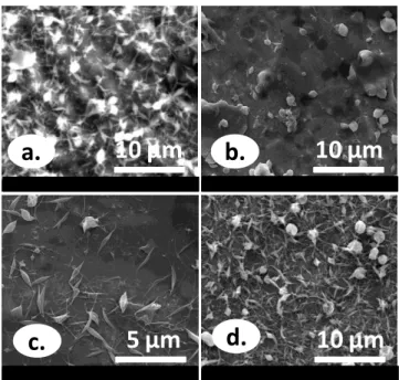
Then we tried to increase percentage of alginate and solutions having 3% (w/v) total concentration including 62% and 75% alginate were prepared (Figure 17a, 17b). But we could not achieve to produce bead-free nanofibers from these solutions. Thus, Figure 17a exhibited bead-on-string structure; whereas only beads were observed in Figure 17b. On the other hand, 4% (w/v) total concentration including 62% and 75% alginate was also prepared (Figure 17c, 17d). In Figure 17c, we observed beads and fibers at the same time; while in Figure 17d, beads were seen rather than bead-free nanofibers.
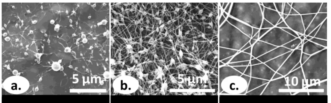
Formation of beads may be the consequence of breaking up of spinning jet due to the high surface tension of the solution [1]. Therefore, we tried to reduce surface tension of the solution. So we added a nonionic surfactant called Triton X-100 into these solutions to improve the electrospinnability of the so-called solutions. In principle, surfactants reduce surface tension of polymer solution. Therefore, it is getting easier to overcome surface tension of polymer solution and indirectly electrospinning is facilitated [1]. But bead-on-string structure observed in Figure 17a did not change much (Figure 18a). On the other side, beaded structure in Figure 17b has changed to bead-on-string with the addition of surfactant (Figure 18b). Addition of Triton X-100 improved the spinnability
28
of both of the solutions prepared from 4% (w/v) total concentration (Figure 18c, 18d). But the effect of Triton X-100 was best seen in Figure 18c.
10 μm
a.
3μm
50 μm
d.
10 μm
c.
b.
Figure 17. SEM images of electrospun alginate/PEO solutions with 3% (w/v)
total polymer concentrations and different ratios (a) 62:28 (b) 75:25; 4% (w/v) total polymer concentrations and different ratios (c) 62:28 (d) 75:25 in aqueous solution.
5 μm
a.
b.
3 μm
10 μm
d.
10 μm
c.
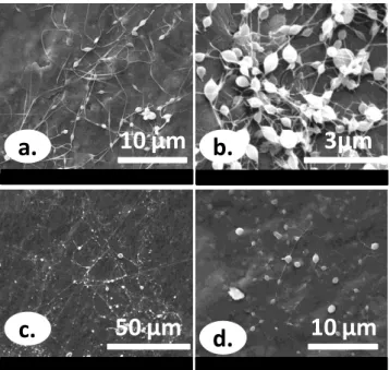
Figure 18. SEM images of electrospun alginate/PEO solutions with 3% (w/v)