ISM Band 1:16 Wilkinson Power Divider
Ahsan Altaf
Department of Electrical and Electronics Engineering Istanbul Medipol University
Istanbul, Turkey [email protected]
Hassan Sajjad
Department of Electrical and Electronics Engineering Istanbul Medipol University
Istanbul, Turkey [email protected]
Sana Khan
Department of Electrical and Electronics Engineering Istanbul Medipol University
Istanbul, Turkey [email protected]
Mehre Munir
Department of Computer Science Iqra National University
Peshawar, Pakistan [email protected]
Abstract—A 1:16 Wilkinson power divider (WPD) working from 1.3 GHz to 3 GHz is presented in this paper. Equal power division, phase and amplitude consistency is achieved among the output ports. The proposed design has a wideband with a 10 dB fractional bandwidth of 76%. The isolation loss within the bandwidth is better than 15 dB and the insertion loss is less than 2 dB. The size of the WPD has been minimized to 16 × 10.7 cm2, which was the main objective of this work. The compact size of the proposed design makes it a suitable candidate for feeding phased antenna arrays for wideband operations.
Index Terms—Wilkinson power divider, N-ways, WLAN, Blue-tooth, ISM Band
I. INTRODUCTION
Power dividers and combiners are vital components of microwave circuits and systems. In order to obtain equal phase and amplitude at the output port, Wilkinson power divider (WPD) is widely use [2]. To attain N-way power division, WPD is more compact in size as compared to other traditional couplers and dividers. It is simple in design, provides high isolation and low insertion loss between the output ports. WPD is narrow band due to the dependence on the quarter wave length line. WPDs are used as feeders in antenna array network [3], power amplifier network [4], and other related subsystems due to their advantage of extraordinary coupling reduction among output ports hence reducing crosstalk. In literature tree and chain are two main configurations of the N-way power divider. Tree topology is a simple structure because it takes next stage in binary form with either the same or changed dimensions while the chain configuration uses consecutive stages in series. The two configurations are shown in the Fig. 1. A power divider with good power handling capabilities is reported in [5] but it increases complexity. To feed phase antenna array transmitter, a three section WPD is used in [6] and [9] but they are large in size. In [10] 4:1 unequal WPD consists of defected ground structure is proposed. A 2 GHz 10:1 WPD is presented in [7]. The proposed WPD has bandwidth of 0.6
In this paper a 1 to 16 WPD is presented. The WPD is designed using microstrip lines on FR4 substrate. The model is simulated in a full wave electromagnetic (FWEM) software. The simulation setup includes the effects of finite substrate, metal thickness and all losses. To design 1:16 WPD, initially 1:2 is designed and then using the tree approach 1:2 is converted to 1:4 WPD. To verify the 1:4 design it is fabricated and measured. The 1:4 WPD design is fabricated using LPKF
(a) Tree Configuration
(b) Chain Configuration Fig. 1: N-way divider configurations
D104 and measured using ANRITHSU network analyzer. The 1 to 4 design is not used for 1:16 WPD configuration because it is not compact in size. The design is modified and results are presented for the modified system. The proposed model has good isolation loss and less insertion loss which are the key performance parameters of the WPD.
II. ANALYSIS ANDDESIGNPROCEDURE
To design a conventional 1 to 2 WPD, the equations are given below.
K =P 3
P 2 (1)
where P3 and P2 represents power at outputs and K quarter
wave impedances at the output ports to achieve desired power level. Z03= Zo r 1 + K2 K3 (2) Z02= Zo3K2 (3)
The characteristic impedance of the system can be used to obtain the isolation resistance R using the following equation.
R = Zo(K +
1
K) (4)
To get equal power at the N output ports, the value of K should be one [9].
III. DESIGN
A. 1:2 Wilkinson Power Divider
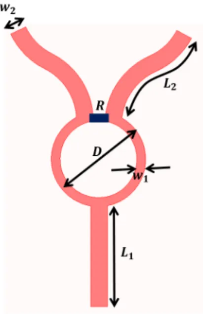
A 1 to 2 WPD is designed on a FR-4 susbtrate. The substrate has a permittivity of 4.7 and a loss tangent of 0.014. The height of the substrate is 60 mils with 1 oz metal thickness and conductivity of 5.8 × 10⁹ S/m. The design is meshed with λ/20 as a meshing size. The isolation resistance R is 100 Ω. The geometry of divider is detailed in Table I. The 1 to 2 WPD schematic and simulation setup is shown in Fig. 2 and Fig. 3 respectively. The designed is simulated and the results
Parameter w1 w2 L1 L2 D
Dimension [mm] 1.4 2.667 17 13.6 13.7
TABLE I: 1:2 WPD dimensions.
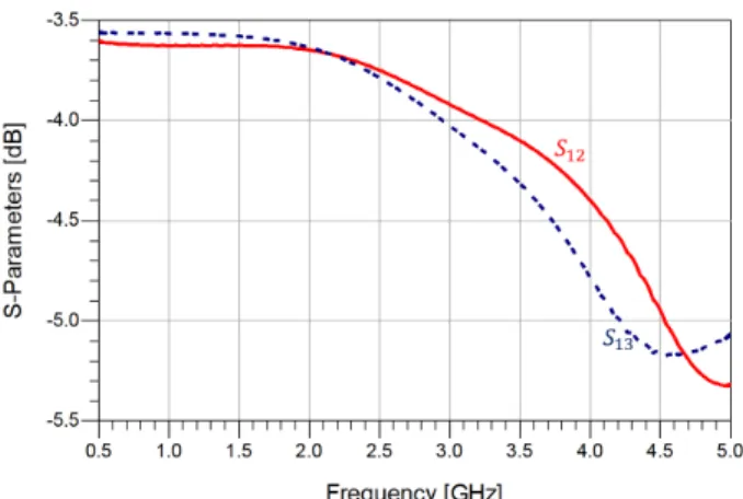
show that the WPD has a 15 dB bandwidth of 1.5 GHz with mitigated loss of insertion below dB.
The system shows a good isolation between output ports and the phases of ports are in good agreement. The S-parameters are shown in Fig. 4 and Fig. 5 while the phase is presented in Fig. 6.
B. 1:4 Wilkinson Power Divider
The tree topology is used to design 1 to 4 WPD by using two 1 to 2 WPD stages. The design parameters, simulation, and material properties of the system are the same as described in the previous section. The design is simulated in an available FWEM software. To verify the results, the system is simulated in an another FWEM software as well. The 3-Dimensional model is presented in Fig. 7. The S-parameters are shown in
Fig. 2: 1:2 WPD Schematic.
Fig. 3: 1:2 WPD configuration
Fig. 4: S-parameters of the configuration.
the Fig. 8 while the insertion loss is described in Fig. 9. The 1 to 4 WPD is fabricated using the LPKF D104 machine, and the results are measured using ANRITHSU‘s network analyzer. The fabricated structure is presented in the Fig. 10. The measured reflection co efficent with the insertion loss is presented in the Fig. 11. It is evident from the measured results
Fig. 5: Insertion loss of the configuration.
Fig. 6: Phase of the output ports.
Fig. 7: 1:4 WPD configuration.
that the 10 dB impedance bandwidth is 2 GHz and the insertion loss is less than 2 dB.
IV. 1:16 WILKINSONPOWERDIVIDER
A. Proposed Design
Aim of this paper is to present a 1 to 16 power divider for phased antenna array. The isolation between the output ports should be high and insertion loss should be low. In addition, the size of the system should also be compact. In order to meet the requirements discussed above, a 1 to 16 WPD is designed in an available FWEM software. The structure of the design is changed in this configuration to make it compact. The proposed model is designed at FR4 substrate with tanδ of 0.014.The thickness of the copper is 0.035 mm with 1.524mm
Fig. 8: Return loss of the 1:4 WPD.
Fig. 9: Insertion loss of the 1:4 WPD.
Fig. 10: Fabricated structure.
height. The size of the proposed system is 160 × 107 mm2 which is compact for this frequency band. The Figure 12 shows the proposed model configuration. The width of the 50 Ω lines are 2.667 mm. The diameter of the 70.7 Ω is 13.7
Fig. 11: Measured results.
Fig. 12: Proposed configuration.
mm while the width is 1.4 mm. The lengths of the model are optimized to get a compact design. The 100 Ω isolation resistor is used by each divider. Each resistor is modeled properly in the simulation setup. The bends used in the design are not sharp rather they are curved to reduce cross talk and stray capacitance at the expense of phase difference. The proposed system can be use to for UWB array configurations.
B. Results & Discussion
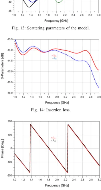
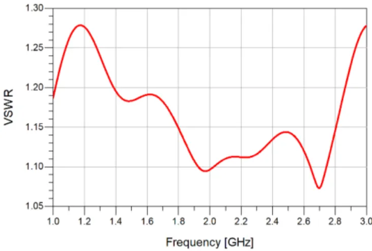
The simulated results show resonation from 1.3 GHz to 2.9 GHz. The 10 dB bandwidth of the proposed system is around 1.6 GHz. The return loss for most of the frequencies are below -15 dB. The isolation loss is well below 15 dB. The operating range have 2dB losses of insertion. The Figure 13 shows the return and isolation loss in decibel scale. The Figure 14 shows the insertion loss while the Fig. 15 illustrates the phase difference between two outports. It is found that phase difference between two ports is less than 2 degree, since it was expected because of the bends used in the design to limit the stray capacitance. The VSWR for the desired bandwidth is less than 1.25 as shown in Fig. 16.
Fig. 13: Scattering parameters of the model.
Fig. 14: Insertion loss.
Fig. 15: Phase difference between the output ports.
V. CONCLUSION
In this paper microstrip lines are used to design and fabricate different configurations of the Wilkinson power divider. A 1 to 2 WPD is designed and simulated. By using the tree topology 1:2 WPD is used to design 1 to 4 WPD. The 1 to 4 WPD is simulated and fabricated as well. Simulation and measurement are well matched. Moreover, 1 to 16 WPD
Fig. 16: VSWR.
is designed and simulated. The dimensions of the model are optimized to get compact size feed network for phased antenna array for ultra wideband operations. The size of the model is 160 × 107 mm2 which is compact for this frequency band. The simulation setup includes the effects of finite substrate, metal thickness and all losses. The results show that the proposed design has very good return loss and isolation loss with below 2 dB insertion loss. The VSWR of the model is below 1.25. The system is designed from 1.3 to 3 GHz frequency range. The desired frequency range cover most of the modern technologies like WLAN, Bluetooth, WiFi and other related devices.
REFERENCES
[1] E. J. Wilkinson, An N-way hybrid power divider, IEEE Trans. Microw. Theory Tech., vol. MTT-8, no. 1, pp. 116118, Jan. 1960.
[2] J. Harvey, E.R. Brown, D.B. Rutledge, R.A York ”Spatial Power Combining for High Power Transmitters,” Article in IEEE Conference, December 2000.
[3] Ulrich H. Gysel, ”A New N-Way Power Divider/Combiner Suitable for High Power Application,” Stanford Research Institute Menlo Park California, 1975.
[4] Yansheng Xu, Renato G. Bosisio, ”Design of Wideband Six and Eight Way Wilkinson Power Dividers Using Stepped Impedance Transform-ers,” Microwave and Optical Technology Letters, Vol. 58, No. 1, January 2016.
[5] Y. Yang, Y. Wang, A.E. Fathy, ”Design of Compact Vivaldi Antenna Arrays for UWB See Through Wall Application,” Progress in Electro-magnetic Research, PIER 82, 401-418, 2008.
[6] Y.Yang, Cemin Zhang, Song Lin, Aly E. Fathy, ”Development of Ultra Wideband Vivaldi Antenna Array,” Article in IEEE conference, 2005. [7] Lim, J.-S., S.-W. Lee, C.-S. Kim, J.-S. Park, D. Ahn, and S. Nam, A
4 : 1 unequal Wilkinson power divider, IEEE Microwave and Wireless Components Letters, Vol. 11, No. 3, 124126, 2001.
[8] Chen, J. X., and Q. Xue, Novel 5 : 1 unequal Wilkinson power divider using offset doublesided parallel-strip lines, IEEE Microwave and Wireless Components Letters, Vol. 17, No. 3, 175177, 2007. [9] Pozar, D. M., Microwave Engineering, John Wiley & Sons, 2009. [10] M. Young, The Technical Writer’s Handbook. Mill Valley, CA: