37.5
Quantitative Comparison
of
Rooftop
and
RWG
Basis Functionst
LEVENT
GUREL*,
IBRAHiM K U ~ A T SENDUR, ANDKUB~LAY
SERTEL DEPARTMENT OF ELECTRICAL AND ELECTRONICS ENGINEERINGBILKENT UNIVERSITY BILKENT, ANKARA, TURKEY
(IgurelQee
.
bilkent . edu. tr)1
Introduction
Integral-equation solvers of computational electromaeetics rely on the representation of the unknown function in terms of some known basis functions (BFs). Among various possible entire-domain and subdomain BFs, piecewise linear function defined on rectangular subdo- mains (referred to as “rooftops” or RTs) [l] and triangular subdomains (due to Rao, Wilton, and Glisson, and referred to as RWGs) [2] are commonly used in the numerical solution of the surface integral equations.
The RT BFs are well-suited for the modeling of geometries that conform to Cartesian coordinates, whereas the RWG BFs are capable of modeling flat-faced approximations of ar- bitrary geometries [2]. Both basis functions can
atso
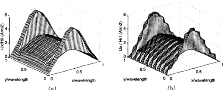
be used in modeling unknown functions transformed from the real space to the parametric space of a curved surface [3-51. The RT and RWG basis functions have many common features: they are defined on two neighboring (touching) subdomains and the unknown is associated with the common edge between these two subdomains; thus they are edge functions; on this common edge the normal component of the current is continuous and has a constant d u e ; on the other edges, the current does not have a normal component; hence no line charges exist at the boundaries of the basis functions. In addition to the shapes of their subdomains, the two BFs also differ in the way they define the direction of the current: the RTs have the same direction (normal to the defining edge) at every point on the two rectangular subdomains, whereas the RWGs are “vector” BFs in the sense that they do not have a constant direction at every point on the two triangular subdomains.Figures l(a) and (b) show the s-directed induced current, which is mo and RWG basis functions, respectively, on a 1 X x 1 X perfect-electric-conduc
placed on the r-y plane. The electric field of the incident plane wave is given by E = ?e-akz
A visual inspection of the current plots of Fig. 1 reveals that the use of the RT BFs results in a smoother approximation of the current ( J z ) along the z direction compared to the use of the RWG BFs. What is most bothersome is to observe that the RWG representation of the current [Fig. l(b)] results in nonzero values of the J, on some triangular subdomains near the 2 = 0 edge, albeit these triangles touch the edge at only one point. However, this observation is not sufficient to claim that the RT BFs model the induced current better than the RWG BFs. A quantitative and thus more conclusive method of comparison would ‘This work was supported in part by NATO’s Scientific Affairs Divlsion in the framework of the Science for Stability Programme and in part by the Scientific and Technical Research Council of Turkey (TUBITAK) under contract EEEAG-163
0-7803-4178-/3/97/$10.00
0
1997 BEEFigure 1: z component of the induced surface current on a 1 A x 1 A PEC patch as modeled by the (a) RT and (b) RWG basis functions.
be desirable to compare these two of the most commonly used BFs of the computational electromagnetics.
2
Boundary-Condition Error (BCE)
A quantitative comparison of the RT and RWG BFs can be achieved by determining how well these BFs satisfy the BCs. Consider the same scattering problem outlined in Section 1. The BCE on this 1 A x 1 X PEC patch is defined as
RCE, = /E:
+
E:l and BCE, = /E;+
E ; [ . (1) where E; = 0 due to t h e choice of the incident field in Eq. ( 1 ) and the scattered field is givenIn the next section, the RT and R\VG BFs will be compared on the basis of BCE as defined in Eqs. (2) and ( 3 ) .
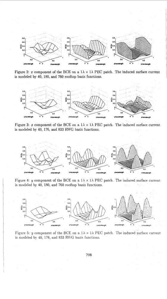
Figure 2:
x
component of the BCE on a 1 X x 1 X PEC patch. The induced surface current is modeled by 40, 180, and 760 rooftop basis functions.Figure 3: x component of the BCE on a 1X x 1 X PEC patch. The induced surface current is modeled by 40, 176, and 833 RWG basis functions.
Figure 4. y component of the BCE on a 1 X x 1 X PEC patch The induced surface current is modeled by 40, 180, and 760 rooftop basis functions.
Figure 5 y component of the BCE on a 1 X x 1 X PEC patch The induced surface current IS modeled bv 40. 176. and 833 RI\G basis fiinctiuns
0.2 + UntRWGs
0 05
0 ’ I 01 I
0 200 400 600 800 1 m 1200 0 200 400 600 Boo loo0 1200 Number of Basis Functkms Number of Basis Functions
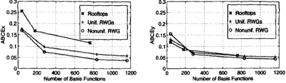
Figure 6: ABCE for the z and y components of the electric field.
finer discretization of the patch. The increase of the BCE at the two edges is also expected since the component of the electric field that is orthogonal to these edges is tangential to the patch inside the edge but is normal to the patch outside the edge, and thus does not satisfy the boundary condition implied in Eq. (2). We also observe in Figs. 2-5 that RWG and RT basis functions induce the same order of BCE for the cases of comparable numbers of BFs. In order to assign single number that will be an indicator of the amount of the BCE plotted in Figs. 2-5, the average BCE (ABCE) is defined as
-
Area of the Patch All Subdomains
1
BCE(Centerof the Subdomain) x {Area of the Sobdomain] 1
ABCE =
(3)
. ,
for both components of the BCE. Figures 6(a) and (b) depict the 2 and y components of theABCE, respectively, for RT and RWG BFs when the patch is uniformly meshed and also for RWG BFs when the patch is nonuniformly meshed such that the subdomains that are closer to the edges are smaller than those closer to the center of the patch.
4
Conclusions
We observe both in Figs. 2-5 and in Figs. 6(a) and (b) that the BCE induced by the RWG and RT BFs are of the same order for the cases of comparable numbers of BFs and that the BCE induced by the RWGs is certainly not more than that of RTs despite the nonzero values of the current normal to the patch edges as depicted in Fig. l(b).
References
[1] A. W. Glisson and D. R. Wilton, “Simple and efficient numerical methods for problems of electre magnetic radiation and scattering from surfaces,” fEEE Trans. Antennas Propagat., vol. AP-28, no. 5,
pp. 593403, Sept. 1980
[2j S. M. Rao, D. R. Wilton, and A . W. Glisson, “Electromagnetic Scattering by Surfaces of Arbitrary Shape,” fEEE Rans. Antennas Propagat., vol. AP-30, pp. 409418, hfay 1982.
[3] .I. M. Song and W. C. Chew, “Moment Method solutions using parametric geometry,” J . Electromagnetit
Waves and Applications, vol. 9, No. 1/2 pp. 71-83, 1995.
[?] L. Valle, F.Rivas, and M. F. CQtedra, “Combining t h e Moment Method with Geometrical Modelling by NURBS Surfaces and Bezier Patches,” IEEE Trans. Antennas Propagat., vol. AP-38, pp. 373-381, Mar. 1993.
151 S. Wandzura, “Electric Current Basis Functions for Curved Surfaces,” Electromagnetics, vol. 12:, pp. 77- 91, 1992.